Lincoln Navigator: Fuel Tank and Lines - 3.5L EcoBoost (272kW/370PS) / Fuel Pump and Sender Unit. Removal and Installation
Special Tool(s) / General Equipment
 |
310-123 Locking Ring, Fuel Tank TKIT-2004J-F TKIT-2005U-LM |
Removal
NOTE: Removal steps in this procedure may contain installation steps.
-
Remove the Fuel Tank.
Refer to: Fuel Tank (310-01 Fuel Tank and Lines - 3.5L EcoBoost (272kW/370PS), Removal and Installation).
-
Remove three nuts and remove the support guard.
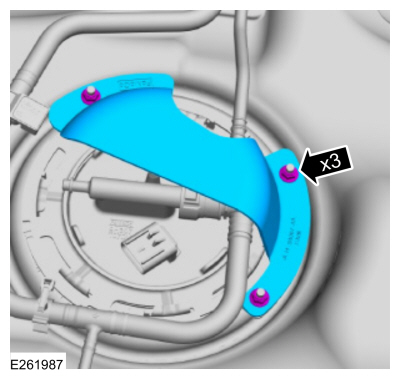 |
-
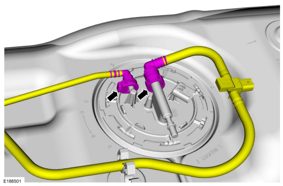
NOTE: To avoid introducing contamination into the fuel tank use compressed air to clean the Fuel Pump and Sender Unit connections, couplings, flange surfaces and the immediate surrounding area of any dirt or foreign material.
Disconnect the fuel feed and fuel vapor tubes.
Refer to: Quick Release Coupling (310-00) .
 |
-
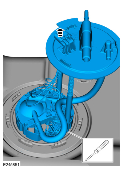
Using the lock ring tool, unlock and remove the Fuel Pump and Sender unit lock ring.
Use Special Service Tool: 310-123 Locking Ring, Fuel Tank.
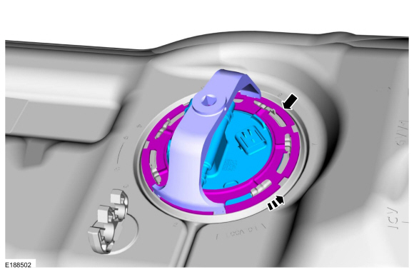 |
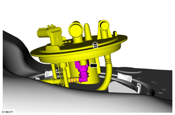
-
Lift the Fuel Pump and Sender unit slightly and disconnect the vent line.
Refer to: Quick Release Coupling (310-00) .
 |
-
NOTE: If the Fuel Pump and Sender Unit does not clear the fuel tank opening, insert a screwdriver into the empty rod hole and slightly pull the screwdriver inboard until the Fuel Pump and Sender Unit aligns with the fuel tank opening.
NOTE: Remove and discard the Fuel Pump Module O-ring seal.
NOTE: Some residual fuel may remain in the Fuel Pump and Sender Unit. Carefully drain into a suitable container.
NOTE: The Fuel Pump and Sender Unit must be handled carefully to avoid damage to the float arm and filter.
NOTE: Inspect the mating surfaces of the Fuel Pump and Sender Unit flange and fuel tank O-ring seal contact surfaces. Wipe clean with a lint free towel. Install a new Fuel Pump and Sender Unit or fuel tank if the Oring seal contact area is bent, scratched or corroded.
Remove the Fuel Pump and Sender Unit.
 |
Installation
-
NOTE: Make sure to install a new Fuel Pump and Sender Unit O-ring seal.
NOTE: Make sure the alignment tabs on the Fuel Pump and Sender Unit and the fuel tank meet prior to tightening the Fuel Pump and Sender Unit lock ring.
To install, reverse the removal procedure.
 Fuel Lines. Removal and Installation
Removal
NOTE:
Removal steps in this procedure may contain installation steps.
With the vehicle in NEUTRAL, position it on a hoist.
Refer to: Jacking and Lifting (100-02 Jacking and Lifting, Description and Operation)...
 Fuel Tank. Removal and Installation
Special Tool(s) /
General Equipment
292-00004Fuel Tanker 100 GPM
Powertrain Jack
Wooden Block
Removal
NOTE:
If the fuel pump is operational, connect the fuel tanker
hose to the engine supply hose...
Other information:
Lincoln Navigator 2018-2026 Workshop Manual: Passive Anti-Theft System (PATS) - Component Location. Description and Operation
Item Description 1 Bluetooth Front Interior Antenna RH (Bluetooth Antenna #3) 2 RFA Module 3 Exterior Front Door Handle RH (Bluetooth Antenna #5) 4 Exterior Rear Door Handle RH (Bluetooth Antenna #12) 5 Bluetooth Rear Interior Antenna RH (Bluetooth Antenna) 6 Bluetooth Rear Exterior Antenna (Bluetooth Antenna #..
Lincoln Navigator 2018-2026 Workshop Manual: Turbocharger Coolant Return Tube LH. Removal and Installation
Materials Name Specification Motorcraft® Metal Brake Parts CleanerPM-4-A, PM-4-B, APM-4-C - Removal NOTICE: The turbocharger compressor vanes can be damaged by even the smallest particles. When removing any turbocharger or engine air intake system component, ensure that no debris enters the system. Failure to do so may result in damage to the tur..
Categories
- Manuals Home
- 4th Gen Lincoln Navigator Service Manual (2018 - 2026)
- Transmission Fluid Drain and Refill. General Procedures
- Identification Codes. Description and Operation
- Rear View Mirrors - System Operation and Component Description. Description and Operation
- Brake Service Mode Activation and Deactivation. General Procedures
- Rear Bumper. Removal and Installation
Rear Stabilizer Bar Link. Removal and Installation
Removal
NOTE: Removal steps in this procedure may contain installation details.
With the vehicle in NEUTRAL, position it on a hoist.Refer to: Jacking and Lifting (100-02 Jacking and Lifting, Description and Operation).
NOTE: Use the hex-holding feature to prevent the stud from turning while removing the nut.
Remove and discard the 2 rear stabilizer bar link nuts and remove the rear stabilizer bar link.Torque: 46 lb.ft (63 Nm)
