
Lincoln Navigator: Seatbelt Systems / Front Seatbelt Retractor and Pretensioner. Removal and Installation
Removal
 WARNING:
The following procedure prescribes critical repair steps
required for correct restraint system operation during a crash. Follow
all notes and steps carefully. Failure to follow step instructions may
result in incorrect operation of the restraint system and increases the
risk of serious personal injury or death in a crash.
WARNING:
The following procedure prescribes critical repair steps
required for correct restraint system operation during a crash. Follow
all notes and steps carefully. Failure to follow step instructions may
result in incorrect operation of the restraint system and increases the
risk of serious personal injury or death in a crash.
NOTE: Removal steps in this procedure may contain installation details.
NOTE: LH shown, RH similar.
-
Refer to: Pyrotechnic Device Health and Safety Precautions (100-00 General Information, Description and Operation).
WARNING:
Before beginning any service procedure in this
manual, refer to health and safety warnings in section 100-00 General
Information. Failure to follow this instruction may result in serious
personal injury.
-
Depower the SRS .
Refer to: Supplemental Restraint System (SRS) Depowering (501-20B Supplemental Restraint System, General Procedures).
-
Remove the upper B-pillar trim panel.
Refer to: B-Pillar Trim Panel (501-05 Interior Trim and Ornamentation, Removal and Installation).
-
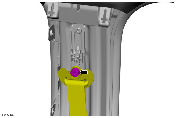
Remove the bolt and position front seatbelt retractor and pretensioner D-ring aside.
Torque: 30 lb.ft (40 Nm)
 |
-
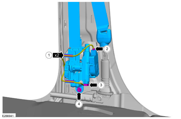
Remove the front seatbelt retractor and pretensioner.
-
Detach the wiring harness retainers.
-
Disconnect the electrical connector.
-
Disconnect the electrical connector.
-
Remove the bolt.
Torque: 30 lb.ft (40 Nm)
-
Detach the wiring harness retainers.
 |
Installation
NOTE: During installation, make sure the seatbelt webbing is not twisted and the seatbelts and buckles are accessible to the occupants.
-
To install, reverse the removal procedure.
-
Repower the SRS .
Refer to: Supplemental Restraint System (SRS) Repowering (501-20B Supplemental Restraint System, General Procedures).
-
Check the seatbelt system for correct operation.
Refer to: Seatbelt System Functional Tests (501-20A Seatbelt Systems, General Procedures).
 Front Seatbelt Buckle. Removal and Installation
Removal
NOTE:
Removal steps in this procedure may contain installation details.
NOTE:
RH seat shown, LH seat similar.
Remove the front seat...
 Seatbelt Shoulder Height Adjuster. Removal and Installation
Removal
NOTE:
Removal steps in this procedure may contain installation details.
NOTE:
LH shown, RH similar.
Remove the upper B-pillar trim panel...
Other information:
Lincoln Navigator 2018-2026 Workshop Manual: Frame Members-Front Frame Section. Removal and Installation
Special Tool(s) / General Equipment Grinder Plasma Cutter MIG/MAG Welding Equipment Locking Pliers Removal NOTE: The following procedure provides steps to replace the front frame short section at the first frame crossmember or the frame section at the center rail joint depending on the extent of vehicle damage...
Lincoln Navigator 2018-2026 Workshop Manual: Instrumentation, Message Center and Warning Chimes - Vehicles With: Head Up Display (HUD). Diagnosis and Testing
Diagnostic Trouble Code (DTC) Chart Diagnostics in this manual assume a certain skill level and knowledge of Ford-specific diagnostic practices. REFER to: Diagnostic Methods (100-00 General Information, Description and Operation). Module DTC Description Action HUD U0100:00 Lost Communication With ECM/PCM 'A': No Sub Type Information GO to Pinpoint Test K HU..
Categories
- Manuals Home
- 4th Gen Lincoln Navigator Service Manual (2018 - 2026)
- Rear Bumper. Removal and Installation
- SYNC Module [APIM]. Removal and Installation
- Remote Function Actuator (RFA) Module. Removal and Installation
- All Terrain Control Module (ATCM). Removal and Installation
- Front Bumper Cover. Removal and Installation
Front Driveshaft. Removal and Installation
Special Tool(s) / General Equipment
Crimping ToolMaterials
Name Specification Motorcraft® Premium Long-Life GreaseXG-1-E1 ESA-M1C75-B
Removal
With the vehicle in NEUTRAL, position the vehicle on a hoist.Refer to: Jacking and Lifting (100-02 Jacking and Lifting, Description and Operation).
Remove the bolts and the transmission shield.
