Lincoln Navigator: Automatic Transmission - 10-Speed Automatic Transmission – 10R80 / A Clutch. Description and Operation
Overview
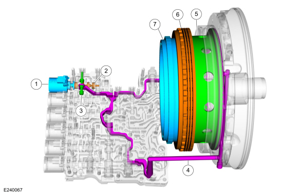
| Item | Description |
| 1 | SSA |
| 2 | A clutch control valve |
| 3 | A clutch latch valve |
| 4 | A clutch apply circuit |
| 5 | A clutch piston |
| 6 | A clutch assembly |
| 7 | Ring gear No. 1 |
Ring gear No. 1 is connected to the A clutch. When the A clutch applies, it holds the ring gear No. 1 stationary.
A Clutch Exploded View
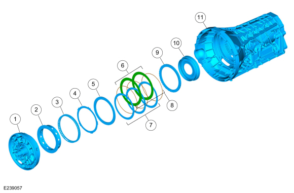
| Item | Description |
| 1 | Front support assembly |
| 2 | A clutch piston |
| 3 | A clutch piston return spring |
| 4 | A clutch wave spring |
| 5 | A clutch apply plate |
| 6 | A clutch steel plates |
| 7 | A clutch friction plates |
| 8 | A clutch separating springs |
| 9 | A clutch pressure plate |
| 10 | Ring gear No. 1 |
| 11 | Transmission case |
A Clutch Hydraulic Circuits
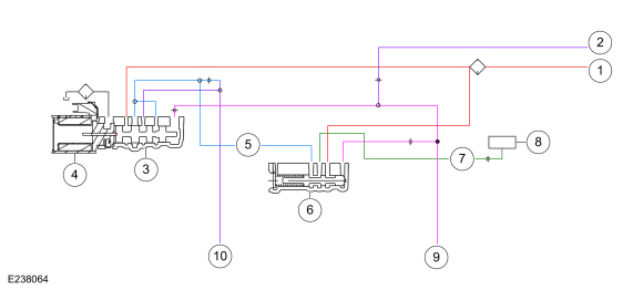
| Item | Description |
| 1 | Line pressure |
| 2 | Pump output |
| 3 | A clutch control valve |
| 4 | SSA |
| 5 | Control pressure to latch valve |
| 6 | A clutch latch valve |
| 7 | Apply pressure to mechanical A clutch |
| 8 | Mechanical A clutch |
| 9 | Elevated exhaust pressure |
| 10 | Clutch exhaust |
A Clutch Hydraulic Operation
Line pressure is supplied to the A clutch control valve and the A clutch latch valve. As SSA turns on, it moves the control valve allowing regulated line pressure to flow to the A clutch latch valve and then to the mechanical A clutch. When the regulated line pressure in the A clutch control circuit reaches approximately 698 kPa (100 psi), the mechanical A clutch is fully applied. The pressure in the A clutch control circuit moves the A clutch latch valve to the left which allows line pressure to hold the mechanical A clutch applied.
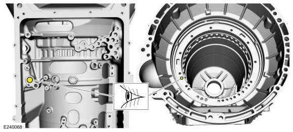
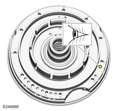
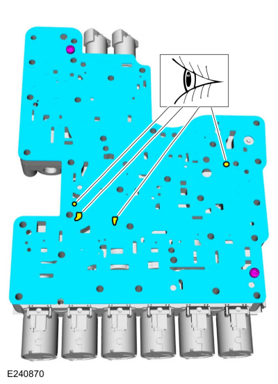
A Clutch Hydraulic Passages
 Transmission Description - System Operation and Component Description. Description and Operation
System Diagram
E339580
*.sttxt {
visibility: hidden;
}
*...
 B Clutch. Description and Operation
Overview
Item
Description
1
SSB
2
B clutch control valve
3
B clutch latch valve
4
B clutch apply circuit
5
B clutch piston
6
B clutch assembly
7
One-Way Clutch (OWC)
..
Other information:
Lincoln Navigator 2018-2026 Workshop Manual: Evaporative Emission Canister. Removal and Installation
Removal WARNING: Do not smoke, carry lighted tobacco or have an open flame of any type when working on or near any fuel-related component. Highly flammable mixtures may be present and may be ignited. Failure to follow these instructions may result in serious personal injury. WARNING: Do not carry personal electronic devices such as cell phones, pagers or ..
Lincoln Navigator 2018-2026 Workshop Manual: Front Stabilizer Bar. Removal and Installation
Removal NOTICE: Suspension fasteners are critical parts that affect the performance of vital components and systems. Failure of these fasteners may result in major service expense. Use the same or equivalent parts if replacement is necessary. Do not use a replacement part of lesser quality or substitute design. Tighten fasteners as specified. NOTE: Removal steps in this proc..
Categories
- Manuals Home
- 4th Gen Lincoln Navigator Service Manual (2018 - 2026)
- Telematics Control Unit (TCU) Module. Removal and Installation
- Neutral Flat Tow Activation and Deactivation. General Procedures
- Transmission Fluid Level Check. General Procedures
- Head Up Display (HUD) Module Calibration. General Procedures
- Vehicle Dynamics Control Module (VDM). Removal and Installation
Axle Tube Bearing. Removal and Installation
Special Tool(s) / General Equipment
 205-123
(T78P-1177-A)
205-123
(T78P-1177-A)
Installer, Axle Shaft Oil Seal
 308-047
(T77F-1102-A)
308-047
(T77F-1102-A)
Remover, Bearing Cup Slide Hammer