Lincoln Navigator: Front Seats / Front Seat Backrest. Removal and Installation
Removal
 WARNING:
The following procedure describes critical repair steps
required for correct seat component installation. Follow all notes and
steps carefully. Do not place any objects between the seat components
and the body of the vehicle, nor any objects within a joint internal to
the seat structure. Failure to follow step instructions may result in
incorrect operation of the seat components and increases the risk of
serious personal injury.
WARNING:
The following procedure describes critical repair steps
required for correct seat component installation. Follow all notes and
steps carefully. Do not place any objects between the seat components
and the body of the vehicle, nor any objects within a joint internal to
the seat structure. Failure to follow step instructions may result in
incorrect operation of the seat components and increases the risk of
serious personal injury.
NOTE: Removal steps in this procedure may contain installation details.
NOTE: Driver seat with power head restraint shown, other seats similar.
-
Remove the front seat.
Refer to: Front Seat (501-10A Front Seats, Removal and Installation).
-
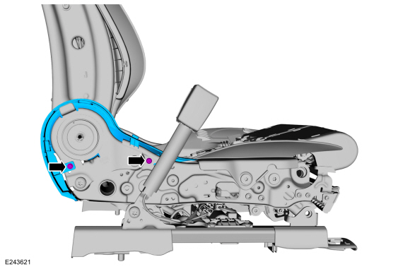
Remove the side shield screws.
 |
-
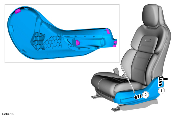
Remove the LH side shield.
-
Lift the side shield and pull outward.
-
Push the side shield forward.
-
Lift the side shield and pull outward.
 |
-
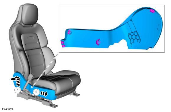
Remove the RH side shield.
-
Lift the side shield and pull outward.
-
Push the side shield forward.
-
Lift the side shield and pull outward.
 |
-
Remove the front seat cushion cover and foam as an assembly.
Refer to: Front Seat Cushion Cover (501-10A Front Seats, Removal and Installation).
-
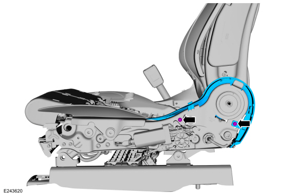
Remove the screws and the LH inner shield.
 |
-
Remove the screws and the RH inner shield.
 |
-
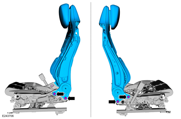
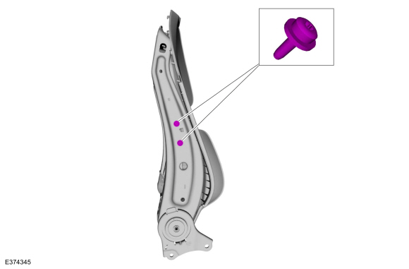
Disconnect the front seat backrest harness electrical connectors.
 |
-
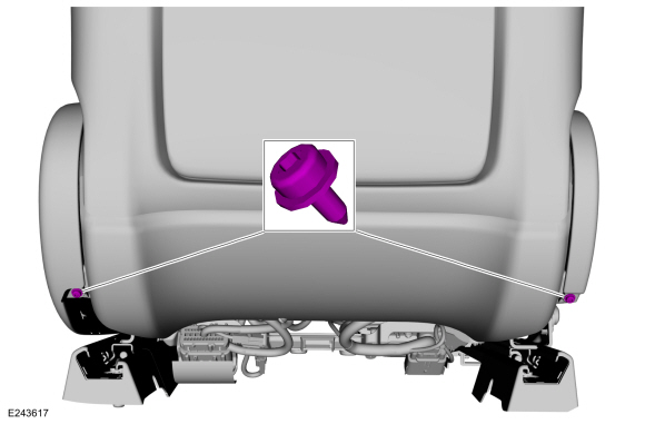
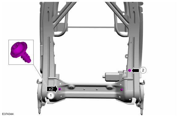
Remove the bolts and the front seat backrest.
Torque: 35 lb.ft (47 Nm)
 |
-
NOTE: This step is only necessary when installing a new component.
Remove the front seat backrest cover.
Refer to: Front Seat Backrest Cover - Vehicles With: Multi-Contour Seats (501-10A Front Seats, Removal and Installation).
Refer to: Front Seat Backrest Cover - Vehicles Without: Multi-Contour Seats (501-10A Front Seats, Removal and Installation).
-
NOTE: This step is only necessary when installing a new component.
Remove the side airbag.
Refer to: Side Airbag (501-20B Supplemental Restraint System, Removal and Installation).
-
NOTE: This step is only necessary when installing a new component.
Remove the front seat power lumbar assembly
Refer to: Front Seat Power Lumbar Assembly - Vehicles With: Multi-Contour Seats (501-10A Front Seats, Removal and Installation).
Refer to: Front Seat Power Lumbar Assembly - Vehicles Without: Multi-Contour Seats (501-10A Front Seats, Removal and Installation).
-
NOTE: This step is only necessary when installing a new component.
Remove the front head restraint guide sleeves.
Refer to: Front Head Restraint Guide Sleeve (501-10A Front Seats, Removal and Installation).
-
NOTE: This step is only necessary when installing a new component.
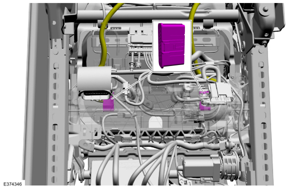
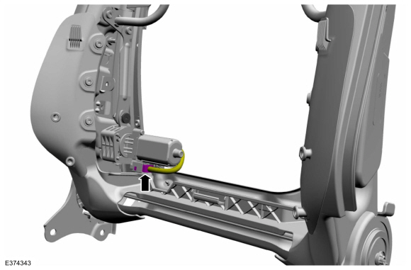
Disconnect the front seat backrest recline motor electrical connector and position aside.
 |
-
NOTE: This step is only necessary when installing a new component.
-
Remove the front seat backrest module screws.
-
Disconnect the front seat backrest module motor bolt.
Torque: 89 lb.in (10 Nm)
-
Remove the front seat backrest module screws.
 |
-
NOTE: This step is only necessary when installing a new component.
Remove the front seat backrest module bolts.
Torque: 89 lb.in (10 Nm)
 |
-
NOTE: This step is only necessary when installing a new component.
Remove the front seat backrest module.
 |
Installation
-
NOTE: Transfer components to the new front seat backrest as necessary.
To install. reverse the removal procedure.
 Front Seat. Removal and Installation
Removal
WARNING:
The following procedure describes critical repair steps
required for correct seat component installation. Follow all notes and
steps carefully...
 Front Seat Backrest Adjuster - Vehicles With: Multi-Contour Seats. Removal and Installation
Removal
NOTE:
Driver seat shown, passenger seat similar.
Remove the front seat backrest cover.
Refer to: Front Seat Backrest Cover - Vehicles With: Multi-Contour Seats (501-10A Front Seats, Removal and Installation)...
Other information:
Lincoln Navigator 2018-2026 Workshop Manual: Ethernet Module Communications Network - System Operation and Component Description. Description and Operation
System Operation System Diagram NOTE: The system diagrams include all component options. Some components may not be equipped on the vehicle. Ethernet Communication Network *.sttxt { visibility: hidden; } *.stcallout { visibility: visible; } E369249 ..
Lincoln Navigator 2018-2026 Workshop Manual: Fuel System Pressure Release. General Procedures
Activation Refer to: Gasoline and Gasoline-Ethanol Fuel Systems Health and Safety Precautions (100-00 General Information, Description and Operation). With the vehicle in NEUTRAL, position it on a hoist. Refer to: Jacking and Lifting (100-02 Jacking and Lifting, Description and Operation). NOTE: The FPDM is located on the LH outboa..
Categories
- Manuals Home
- 4th Gen Lincoln Navigator Service Manual (2018 - 2026)
- Front Seat. Removal and Installation
- Rear Bumper. Removal and Installation
- Transmission Fluid Level Check. General Procedures
- Head Up Display (HUD) Module Calibration. General Procedures
- Front Bumper Cover. Removal and Installation
Front Driveshaft. Removal and Installation
Special Tool(s) / General Equipment
Crimping ToolMaterials
Name Specification Motorcraft® Premium Long-Life GreaseXG-1-E1 ESA-M1C75-B
Removal
With the vehicle in NEUTRAL, position the vehicle on a hoist.Refer to: Jacking and Lifting (100-02 Jacking and Lifting, Description and Operation).
Remove the bolts and the transmission shield.