Lincoln Navigator: Instrumentation, Message Center and Warning Chimes / Instrument Panel Cluster (IPC). Removal and Installation
Removal
NOTE:
Removal steps in this procedure may contain installation details.
-
NOTE:
If installing a new module, it is necessary to
upload the module configuration information to the scan tool prior to
removing the module. This information must be downloaded into the new
module after installation.
Using a diagnostic scan tool, begin the PMI process for the IPC
following the on-screen instructions. Record the odometer value from the
original IPC . If the odometer value cannot be obtained from the IPC
(display failure), perform the diagnostic routine. If the value cannot
be obtained after the diagnostic routine, the customer should supply
the approximate odometer value.
-
Remove the FDIM .
Refer to: Information and Entertainment System - Component Location
(415-00 Information and Entertainment System - General Information -
Vehicles With: SYNC 4, Description and Operation).
-
Remove the gear shift module.
Refer to: Gear Shift Module (GSM) (307-05 Automatic Transmission External Controls, Removal and Installation).
-
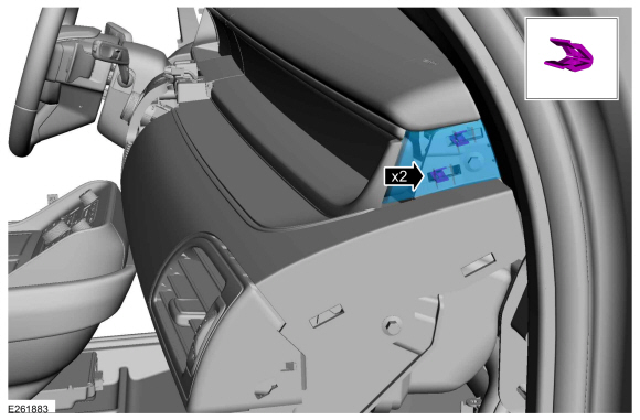
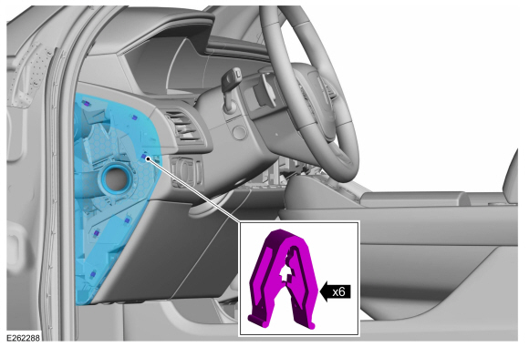
Remove the RH instrument panel trim cover.
-
Release the clips and remove the RH trim cover.
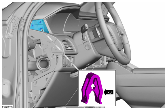
-
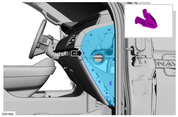
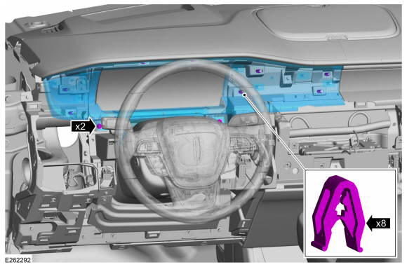
Remove the screws, separate the clips and position the center instrument panel trim panel forward.
Torque:
22 lb.in (2.5 Nm)
-
Disconnect the electrical connectors and remove the center instrument panel trim panel.
-
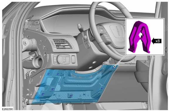
Remove the LH instrument panel trim cover.
-
Release the clips and remove the LH trim cover.
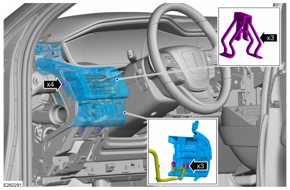
-
Release the clips and remove the lower steering column trim panel.
-
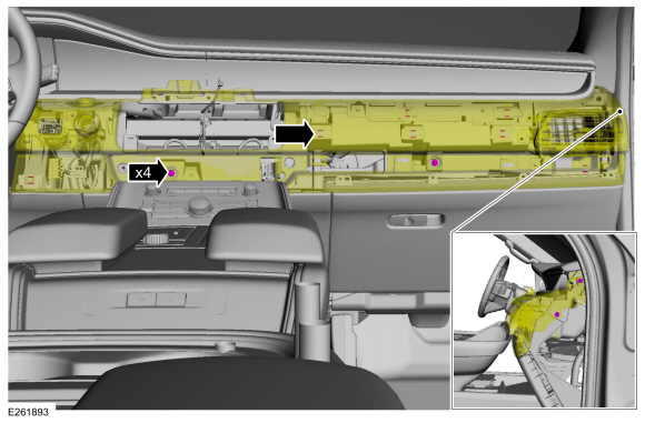
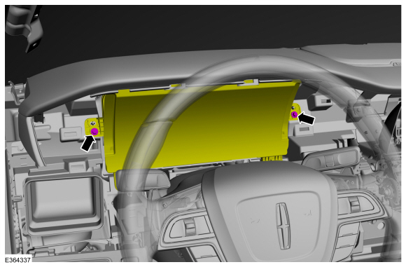
Remove the LH instrument panel finish panel.
-
Remove the bolts and release the clips.
Torque:
22 lb.in (2.5 Nm)
-
Disconnect the electrical connector.
-
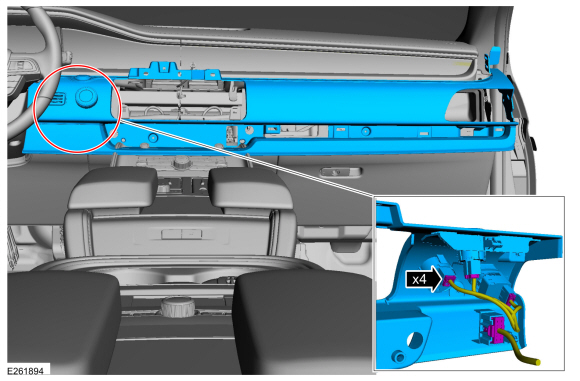
Remove the bolts, release the clips and remove the IPC bezel.
Torque:
22 lb.in (2.5 Nm)
-
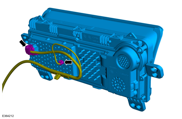
Remove the IPC bolts.
Torque:
22 lb.in (2.5 Nm)
-
Disconnect the electrical connector and Remove the IPC .
Installation
-
To install, reverse the removal procedure.
-
NOTE:
This step is only necessary when installing a new component.
-
Using a diagnostic scan tool, complete the PMI process for the IPC following the on-screen instructions.
-
Using a diagnostic scan tool, complete the FDRS Module Configuration
process for the new IPC following the on-screen instructions.
Activation
WARNING:
Before beginning any service procedure in this section,
refer to Safety Warnings in section 100-00 General Information...
Removal
Remove the IPC .
Refer to: Instrument Panel Cluster (IPC) (413-01 Instrumentation, Message Center and Warning Chimes, Removal and Installation)...
Other information:
Check
NOTE:
Perform the following pre-checks to make sure module programming completes without errors.
Start the programming session in Key OFF, Engine OFF and prior to initiating programming, turn to KOEO .
Make sure the vehicle battery is fully charged or is
connected to a battery charger...
Special Tool(s) /
General Equipment
Interior Trim Remover
Removal
NOTE:
LH side shown, RH side similar.
NOTE:
Removal steps in this procedure may contain installation details.
Remove the front door trim panel...
 Seatbelt Minder Deactivating/Activating. General Procedures
 Instrument Panel Cluster (IPC) Lens. Removal and Installation