Lincoln Navigator: Handles, Locks, Latches and Entry Systems / Front Door Latch. Removal and Installation
Special Tool(s) / General Equipment
| Interior Trim Remover |
Removal
NOTE: LH side shown, RH side similar.
NOTE: Removal steps in this procedure may contain installation details.
-
Remove the front door trim panel.
Refer to: Front Door Trim Panel (501-05 Interior Trim and Ornamentation, Removal and Installation).
-
Remove the exterior front door handle.
Refer to: Exterior Front Door Handle (501-14 Handles, Locks, Latches and Entry Systems) .
-
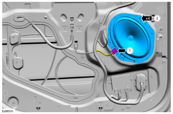
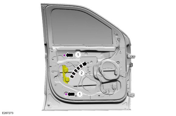
Remove the front door speaker.
-
Disconnect the front door speaker electrical connector.
-
Remove the screws and the front door speaker.
Torque: 13 lb.in (1.5 Nm)
-
Disconnect the front door speaker electrical connector.
 |
-
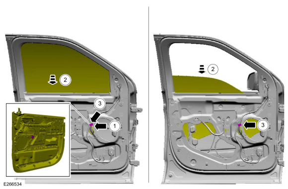
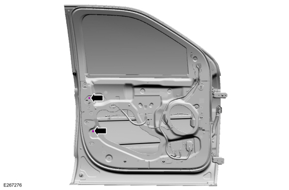
Position the front door window glass to the three quarters down position.
-
Connect the front door trim panel electrical connector.
-
Position the front door window glass to the three quarters down position.
-
Disconnect the front door trim panel electrical connector.
-
Connect the front door trim panel electrical connector.
 |
-
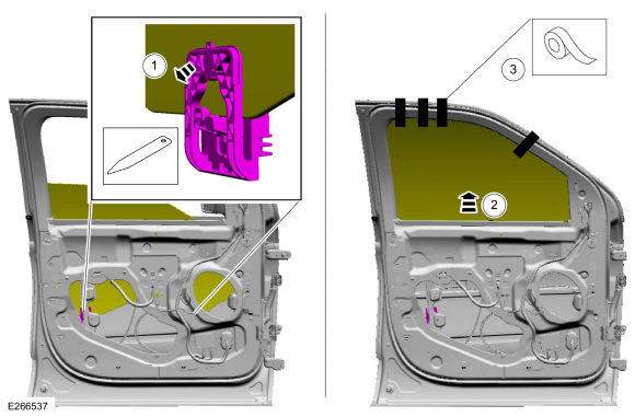
Release the front door window glass and tape in the full up position.
-
Release the front door window glass retaining clips.
Use the General Equipment: Interior Trim Remover
-
Raise the front door window glass to the full up position.
-
Tape the front door window glass in the full up position.
-
Release the front door window glass retaining clips.
 |
-
Remove the adhesive cover from the rear half of the front door window regulator.
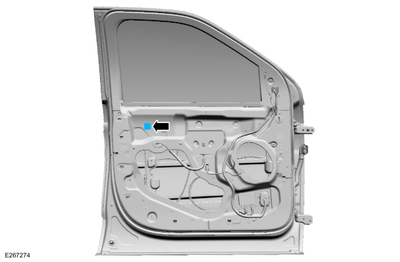 |
-
Position the rear half of the front door window regulator aside.
-
Remove the front door window regulator nuts.
Torque: 93 lb.in (10.5 Nm)
-
Position the rear half of the front door window regulator aside.
-
Remove the front door window regulator nuts.
 |
-
Remove the screw from the exterior front door handle reinforcement.
Torque: 62 lb.in (7 Nm)
 |
-
Remove the front door glass run and bracket bolt upper adhesive cover.
 |
-
Remove the front door glass run and bracket bolts.
Torque: 19 lb.in (2.2 Nm)
 |
-
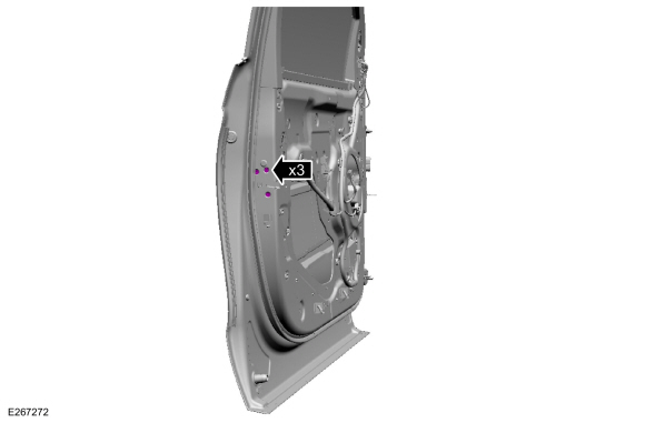
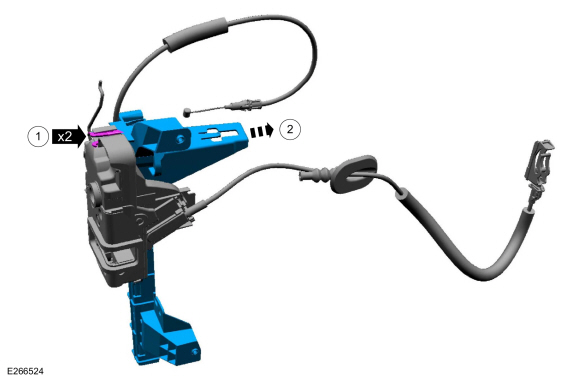
Remove the front door latch bolts.
Torque: 71 lb.in (8 Nm)
 |
-
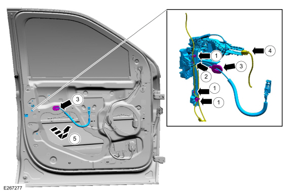
Remove the front door latch.
-
Disconnect the wiring harness routing clips.
-
Disconnect the front door latch electrical connector.
-
Route the interior front door handle cable through the inner door.
-
Position the exterior front door handle electrical connector aside.
-
Remove the front door latch.
-
Disconnect the wiring harness routing clips.
 |
-
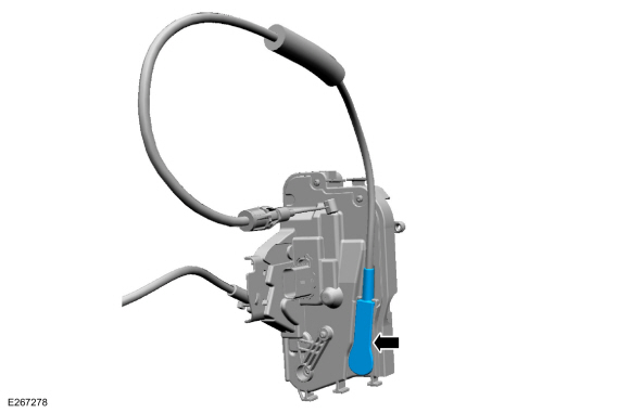
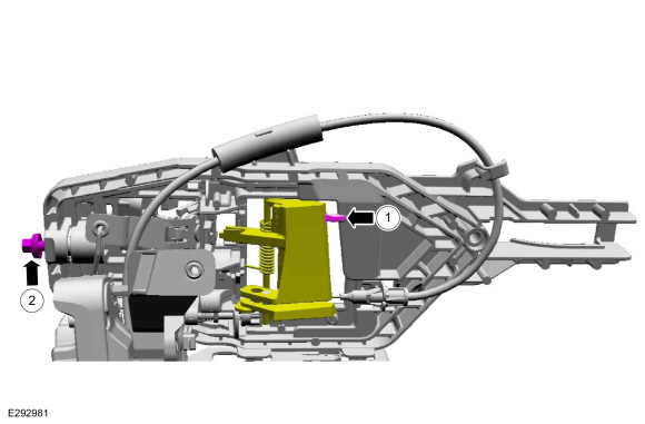
NOTE: This step is only necessary when installing a new component.
Release the cable tension by turning the release screw until the handle lever releases from the stop.
-
Turn the release screw until the handle lever releases from the stop.
-
Release the handle lever from the stop.
-
Turn the release screw until the handle lever releases from the stop.
 |
-
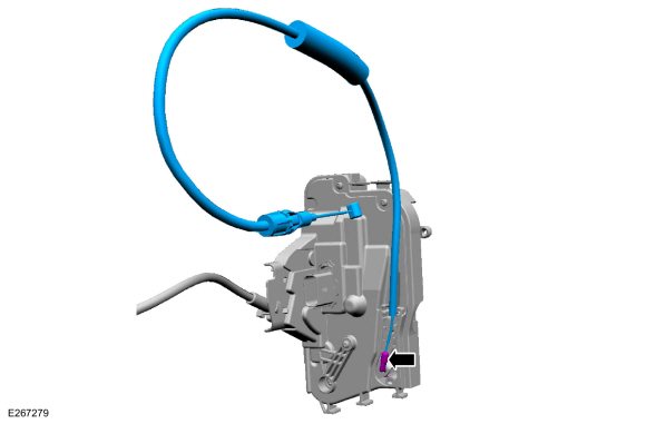
NOTE: This step is only necessary when installing a new component.
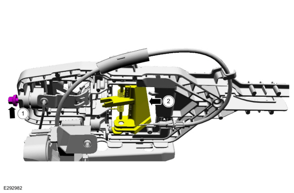
Remove the exterior front door handle reinforcement.
-
Press the locking tab down.
-
If equipped, disconnect the door lock cylinder rod.
Detach the exterior front door handle reinforcement.
-
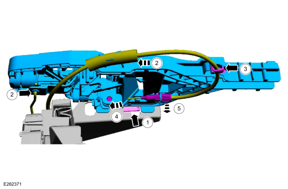
Remove the cable from the routing clip.
-
Remove the cable eyelet from the lever.
-
Detach the cable from the exterior front door handle reinforcement.
-
Press the locking tab down.
 |
-
Remove the front door glass run and bracket.
-
Release the retaining tabs on the front door glass run and bracket.
-
Remove the front door glass run and bracket.
-
Release the retaining tabs on the front door glass run and bracket.
 |
-
NOTE: This step is only necessary when installing a new component.
Remove the exterior front door handle reinforcement to front door latch cable access cover.
 |
-
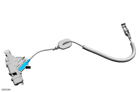
NOTE: This step is only necessary when installing a new component.
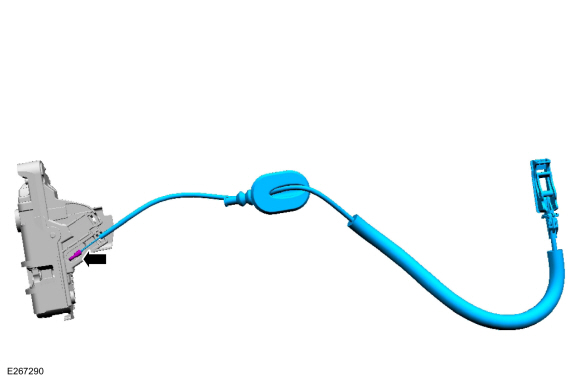
Remove the exterior front door handle reinforcement to front door latch cable.
 |
-
NOTE: This step is only necessary when installing a new component.
Remove the interior front door handle cable access cover.
 |
-
NOTE: This step is only necessary when installing a new component.
Remove the interior front door handle cable.
 |
Installation
-
To install, reverse the removal procedure.
-
NOTE: This step is only necessary when installing a new component.
NOTE: This step must be done correctly or the exterior door handle will not engage the lever on installation.
Position the exterior front door handle reinforcement in the service position.
-
While keeping tension on the cable and holding the handle lever in the engaged position against the stop.
-
Turn the release screw until the handle lever is positioned against the stop.
-
While keeping tension on the cable and holding the handle lever in the engaged position against the stop.
 |
-
Carry out the power door window initialization.
Refer to: Power Door Window Initialization (501-11 Glass, Frames and Mechanisms, General Procedures).
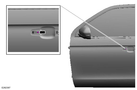
 Front Door Keyless Entry Antenna. Removal and Installation
Special Tool(s) /
General Equipment
Rivet Gun
Removal
NOTE:
LH side shown, RH side similar.
NOTE:
Removal steps in this procedure may contain installation details...
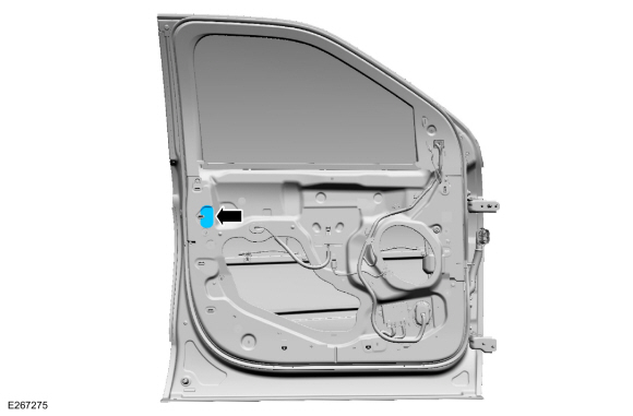
 Front Door Lock Control Switch. Removal and Installation
Removal
NOTE:
LH side shown, RH side similar.
Remove the front door trim panel.
Refer to: Front Door Trim Panel (501-05 Interior Trim and Ornamentation, Removal and Installation)...
Other information:
Lincoln Navigator 2018-2026 Workshop Manual: Instrument Panel Cluster (IPC) Lens. Removal and Installation
Removal Remove the IPC . Refer to: Instrument Panel Cluster (IPC) (413-01 Instrumentation, Message Center and Warning Chimes, Removal and Installation). Release the tabs and remove the IPC lens. Installation To install, reverse the removal procedure...
Lincoln Navigator 2018-2026 Workshop Manual: D-Pillar Moulding. Removal and Installation
Special Tool(s) / General Equipment Blind Rivet Gun 6 mm Drill Bit Removal NOTE: LWB (long wheel base) shown, SWB (short wheel base) similar. NOTE: RH side shown, LH side similar. Open the liftgate...
Categories
- Manuals Home
- 4th Gen Lincoln Navigator Service Manual (2018 - 2026)
- Rear View Mirrors - System Operation and Component Description. Description and Operation
- SYNC Module [APIM]. Removal and Installation
- Neutral Flat Tow Activation and Deactivation. General Procedures
- Transmission Fluid Level Check. General Procedures
- Front Seat. Removal and Installation
Front Stabilizer Bar Link. Removal and Installation
Removal
NOTICE: Suspension fasteners are critical parts that affect the performance of vital components and systems. Failure of these fasteners may result in major service expense. Use the same or equivalent parts if replacement is necessary. Do not use a replacement part of lesser quality or substitute design. Tighten fasteners as specified.
NOTE: Removal steps in this procedure may contain installation details.
With the vehicle in NEUTRAL, position it on a hoist.Refer to: Jacking and Lifting (100-02 Jacking and Lifting, Description and Operation).
NOTICE: Do not use power tools to remove or install the stabilizer bar