Lincoln Navigator: Parking Aid - Vehicles With: Parking Aid Camera / Front Parking Aid Camera. Removal and Installation
Removal
-
Remove the front bumper cover.
Refer to: Front Bumper Cover (501-19 Bumpers, Removal and Installation).
-
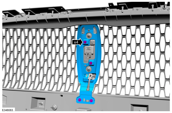
Remove the screws and the bracket.
 |
-
Remove the front parking aid camera and washer nozzle as an assembly.
 |
-
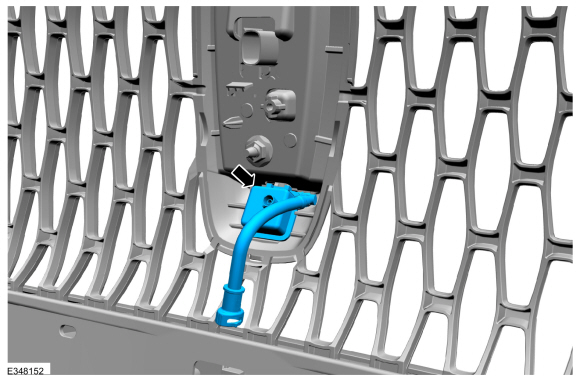
If equipped.
Remove the front parking aid camera washer nozzle.
 |
Installation
All vehicles
-
To install, reverse the removal procedure.
Vehicles equipped with front and rear only parking aid camera
-
Using a diagnostic scan tool, following the on
screen instructions for the LIN New Module Initialization-BCM initialize
the BCM .
Refer to: Parking Aid Camera Initialization (413-13B Parking Aid - Vehicles With: Parking Aid Camera, General Procedures).
Vehicles equipped with 360° cameras only
-
Using a diagnostic scan tool, following the on
screen instructions for the LIN New Module Initialization-IPMB
initialize the IPMB .
Refer to: Parking Aid Camera Initialization (413-13B Parking Aid - Vehicles With: Parking Aid Camera, General Procedures).
-
Align the 360° cameras.
Refer to: 360 Degree View Camera Alignment (413-13B Parking Aid - Vehicles With: Parking Aid Camera, General Procedures).
Vehicles equipped with 360° camera and Trailer Reverse Guidance
-
Using a diagnostic scan tool, following the on
screen instructions for the LIN New Module Initialization-IPMB
initialize the IPMB .
Refer to: Parking Aid Camera Initialization (413-13B Parking Aid - Vehicles With: Parking Aid Camera, General Procedures).
-
Align the 360° cameras.
Refer to: 360 Degree View Camera Alignment (413-13B Parking Aid - Vehicles With: Parking Aid Camera, General Procedures).
 Parking Aid Camera Initialization. General Procedures
NOTE:
On vehicles equipped with Trailer Reverse Guidance (TRG)
complete this procedure and also perform the Trailer Reverse Guidance
camera alignment...
 Rear Parking Aid Camera. Removal and Installation
Removal
NOTE:
Removal steps in this procedure may contain installation details.
Remove the reversing lamp.
Refer to: Reversing Lamp (417-01 Exterior Lighting, Removal and Installation)...
Other information:
Lincoln Navigator 2018-2026 Workshop Manual: Front Door Tweeter Speaker. Removal and Installation
Special Tool(s) / General Equipment Interior Trim Remover Removal Release the clips, disconnect the electrical connector and remove the front door sail trim panel. Use the General Equipment: Interior Trim Remover Remove the screws and the front door tweeter speaker...
Lincoln Navigator 2018-2026 Workshop Manual: Driveshaft Universal Joint. Disassembly and Assembly
Special Tool(s) / General Equipment 205-086 (T74P-4635-C) Installer/Remover, C-Frame and Screw Vise Materials Name Specification Motorcraft® Premium Long-Life GreaseXG-1-E1 ESA-M1C75-B DISASSEMBLY NOTICE: Do not, under any circumstance, clamp the driveshaft assembly in the jaws of a vise or similar holding fixture...
Categories
- Manuals Home
- 4th Gen Lincoln Navigator Service Manual (2018 - 2026)
- Power Running Board (PRB). Diagnosis and Testing
- Transmission Fluid Drain and Refill. General Procedures
- Remote Function Actuator (RFA) Module. Removal and Installation
- Rear View Mirrors - System Operation and Component Description. Description and Operation
- Windshield Washer Pump. Removal and Installation
Rear Drive Axle and Differential. Diagnosis and Testing
Symptom Chart(s)
Diagnostics in this manual assume a certain skill level and knowledge of Ford-specific diagnostic practices.
REFER to: Diagnostic Methods (100-00 General Information, Description and Operation).
Symptom Chart - Differential
Symptom Chart - Differential
Condition Actions Axle overheating GO to Pinpoint Test A Broken gear teeth on the ring gear or pinion GO to Pi