Lincoln Navigator: Body Closures / Front Door Alignment. General Procedures
Inspection
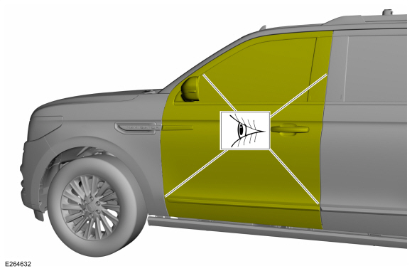
NOTE: LH side shown, RH side similar.
-
Check the body-to-front door dimensions.
Refer to: Body and Frame (501-26 Body Repairs - Vehicle Specific Information and Tolerance Checks, Description and Operation).
Adjustment
All alignments
-
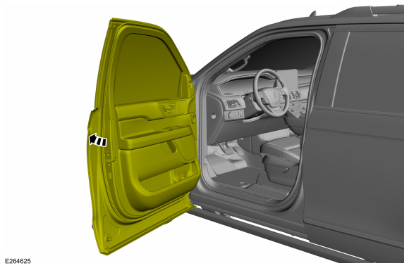
Open the front door.
 |
-
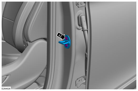
Remove the bolts and the striker assembly.
 |
Front door in and out, up and down alignment
-
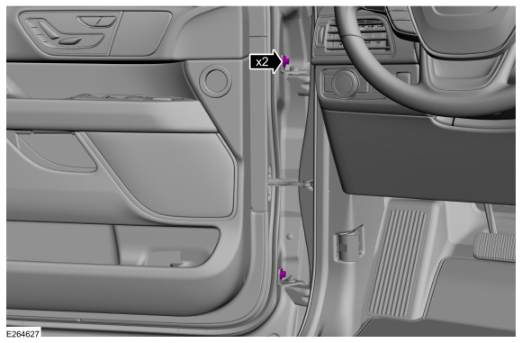
Loosen the bolts enough to permit movement of the door.
 |
-
Adjust the door to specification.
Refer to: Body and Frame (501-26 Body Repairs - Vehicle Specific Information and Tolerance Checks, Description and Operation).
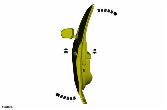 |
-
Tighten the bolts.
Torque: 35 lb.ft (48 Nm)
|
Front door fore, aft and tilt alignment
-
Loosen the bolts enough to permit movement of the door.
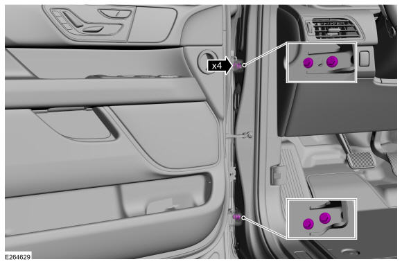 |
-
Carefully close the door.
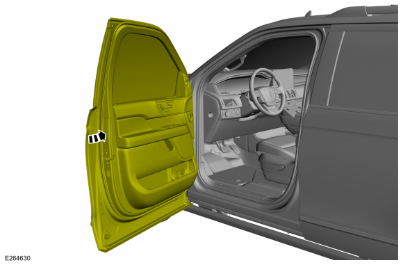 |
-
Adjust the door to specification.
Refer to: Body and Frame (501-26 Body Repairs - Vehicle Specific Information and Tolerance Checks, Description and Operation).
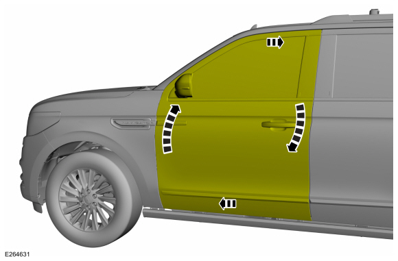 |
-
Carefully open the door.
|
-
Tighten the bolts.
Torque: 24 lb.ft (32 Nm)
|
All alignments
-
Install the striker assembly and the bolts.
Torque: 18 lb.ft (25 Nm)
|
-
Check the body-to-front door dimensions.
Refer to: Body and Frame (501-26 Body Repairs - Vehicle Specific Information and Tolerance Checks, Description and Operation).
 |
 Body Closures. Diagnosis and Testing
Diagnostic Trouble Code (DTC) Chart
Diagnostics in this manual assume a certain skill level and knowledge of Ford-specific diagnostic practices. REFER to: Diagnostic Methods (100-00 General Information, Description and Operation)...
 Hood Alignment. General Procedures
Inspection
Inspect the hood-to-body dimensions.
Refer to: Body and Frame (501-26 Body Repairs - Vehicle Specific Information and Tolerance Checks, Description and Operation)...
Other information:
Lincoln Navigator 2018-2026 Workshop Manual: Valve Train Analysis. General Procedures
Valve Train Analysis - Engine Off, Valve Cover Removed NOTE: The following component inspections are used to diagnose valve train concerns. Check for damaged or severely worn parts and correct assembly. Valve Train Analysis - Camshaft Lobe Lift Remove the spark plugs...
Lincoln Navigator 2018-2026 Workshop Manual: Power Mirrors Synchronization. General Procedures
Synchronization NOTE: The power folding mirrors may need to be synchronized any time the mirrors are folded or unfolded without using the folding switch, or if a new power folding mirror is installed. NOTE: The power telescoping mirrors may need to be synchronized any time the mirrors are extended or retracted without using the telescoping switch, or if a new power telescoping..
Categories
- Manuals Home
- 4th Gen Lincoln Navigator Service Manual (2018 - 2026)
- Remote Function Actuator (RFA) Module. Removal and Installation
- All Terrain Control Module (ATCM). Removal and Installation
- Front Bumper Cover. Removal and Installation
- Neutral Flat Tow Activation and Deactivation. General Procedures
- Windshield Washer Pump. Removal and Installation
Rear Stabilizer Bar Link. Removal and Installation
Removal
NOTE: Removal steps in this procedure may contain installation details.
With the vehicle in NEUTRAL, position it on a hoist.Refer to: Jacking and Lifting (100-02 Jacking and Lifting, Description and Operation).
NOTE: Use the hex-holding feature to prevent the stud from turning while removing the nut.
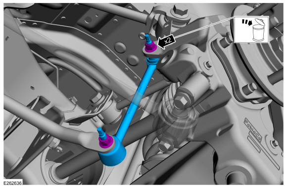
Remove and discard the 2 rear stabilizer bar link nuts and remove the rear stabilizer bar link.Torque: 46 lb.ft (63 Nm)