Lincoln Navigator: Engine - 3.5L EcoBoost (272kW/370PS) / Front Cover to Coolant Pipe Seal. Removal and Installation
Special Tool(s) / General Equipment
 |
303-1528 Remover/Installer, Water Tube Seal |
Removal
NOTICE: During engine repair procedures, cleanliness is extremely important. Any foreign material, including any material created while cleaning gasket surfaces that enters the oil passages, coolant passages or the oil pan, may cause engine failure.
-
Remove the coolant pump.
Refer to: Coolant Pump (303-03 Engine Cooling - 3.5L EcoBoost (272kW/370PS), Removal and Installation).
-
-
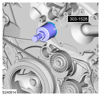
Using the special tool, remove the front cover to coolant pipe seal.
Use Special Service Tool: 303-1528 Remover/Installer, Water Tube Seal.
-
Reset the special tool center bolt to its retracted position.
-
Screw the special tool onto the front cover to coolant pipe seal until it bottoms out.
-
Using a brass hammer, give the special tool a slight tap inward to break front cover radial seal lose.
-
Turn the special tool center bolt clockwise and remove the front cover to coolant pipe seal.
-
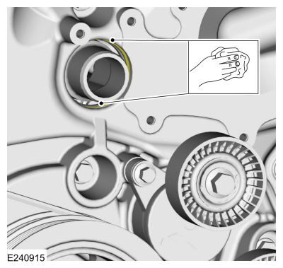
Using the special tool, remove the front cover to coolant pipe seal.
 |
-
Clean the engine front cover to coolant pipe seal area.
 |
Installation
-
-
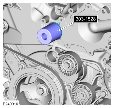
Using the special tool, install the front cover to coolant pipe seal.
Use Special Service Tool: 303-1528 Remover/Installer, Water Tube Seal.
-
Position the front cover to coolant pipe seal on the special tool.
-
Position the special tool into the engine front cover.
-
Using a brass hammer, tap the special tool until the front cover to coolant pipe seal bottoms out.
-
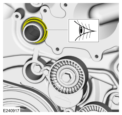
Using the special tool, install the front cover to coolant pipe seal.
 |
-
Inspect the front cover to coolant pipe seal for proper installation or damage.
 |
-
Install the coolant pump.
Refer to: Coolant Pump (303-03 Engine Cooling - 3.5L EcoBoost (272kW/370PS), Removal and Installation).
 Flexplate. Removal and Installation
Removal
Remove the transmission.
Refer to: Transmission (307-01 Automatic Transmission - 10-Speed Automatic Transmission – 10R80, Removal and Installation)...
 Hydraulic Lash Adjuster. Removal and Installation
Removal
Remove the roller finger follower.
Refer to: Rocker Arm (303-01 Engine - 3.5L EcoBoost (272kW/370PS), Removal and Installation)...
Other information:
Lincoln Navigator 2018-2026 Workshop Manual: Driver Side Footwell Air Discharge Temperature Sensor. Removal and Installation
Removal NOTE: Removal steps in this procedure may contain installation details. Remove the climate control housing. Refer to: Climate Control Housing (412-00 Climate Control System - General Information, Removal and Installation)...
Lincoln Navigator 2018-2026 Workshop Manual: Instrument Panel Cluster (IPC) - Overview. Description and Operation
Overview The IPC uses gauges, warning and informational indicators, RTT indicators, warning messages and chimes to alert the driver of vehicle conditions and system operation. The message center provides menu selections to configure various vehicle features...
Categories
- Manuals Home
- 4th Gen Lincoln Navigator Service Manual (2018 - 2026)
- Vehicle Dynamics Control Module (VDM). Removal and Installation
- Front Bumper Cover. Removal and Installation
- Head Up Display (HUD) Module Calibration. General Procedures
- Windshield Washer Pump. Removal and Installation
- SYNC Module [APIM]. Removal and Installation
Axle Tube Bearing. Removal and Installation
Special Tool(s) / General Equipment
 205-123
(T78P-1177-A)
205-123
(T78P-1177-A)
Installer, Axle Shaft Oil Seal
 308-047
(T77F-1102-A)
308-047
(T77F-1102-A)
Remover, Bearing Cup Slide Hammer