Lincoln Navigator: Instrumentation, Message Center and Warning Chimes / Instrument Panel Cluster (IPC) - Overview. Description and Operation
Overview
The IPC uses gauges, warning and informational indicators, RTT indicators, warning messages and chimes to alert the driver of vehicle conditions and system operation. The message center provides menu selections to configure various vehicle features. For a complete list and description of the features the message center controls, refer to the Owner's Literature.
Informational indicators inform the driver of conditions that exist in the vehicle. Warning indicators provide information to the driver of conditions that could potentially cause personal injury or alter vehicle performance.
RTT indicators illuminate in the message center and replace traditional informational or warning indicators, using the same iconic representation. The message center uses a rotating RTT display area that can display multiple indicators, dedicated RTT displays and fixed locations for other RTT indicators and displays.
The IPC utilizes a color Thin Film Transistor (TFT) display for all cluster information. This is a complete virtual IPC without any analog gauges or LED-type indicators. All indicators and gauges appear similar to standard analog gauges and LED indicators found in other analog Instrument Panel Clusters (IPCs).
In some instances a display replaces the current display. In other instances, newly selected displays (such as the message, audio or phone center menus, TPMS or trip computer displays) overlay a currently displayed item, replacing the current display. In these instances, the current display may move to another location. Due to the nature of the virtual cluster, the cluster displays and the level of detail may change based on driver selections. For additional information related to the IPC displays, setup and message center menu selections, refer to the Owner Literature.
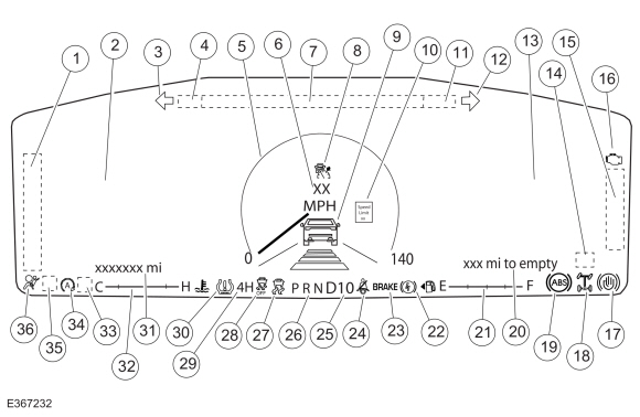
12-Inch Display IPC
IPC
NOTE: The illustration shows the basic display elements. The elements displayed and the layout changes based on driver selections. For additional information about specific feature displays, refer to the Owner's Literature.
| Item | Description |
|---|---|
| 1 |
|
| 2 |
|
| 3 | LH turn indicator |
| 4 | Compass display |
| 5 | Virtual speedometer |
| 6 | Digital speedometer display |
| 7 | Audio information display |
| 8 | Cruise control/ACC RTT indicator |
| 9 |
|
| 10 | Speed limit recognition display |
| 11 | Outside air temperature display |
| 12 | RH turn indicator |
| 13 |
|
| 14 | Overspeed warning RTT indicator (Gulf Cooperative Countries [GCC]) |
| 15 |
|
| 16 | MIL |
| 17 | Auto hold RTT indicator |
| 18 | ELD RTT indicator |
| 19 | ABS indicator |
| 20 | DTE display |
| 21 | Virtual fuel gauge |
| 22 | Electronic parking brake indicator |
| 23 | Brake warning indicator |
| 24 | Seatbelt warning indicator |
| 25 | SelectShift display |
| 26 | PRND display |
| 27 | Stability-traction control (sliding car icon) indicator |
| 28 | Traction control disabled (sliding car OFF icon) indicator |
| 29 | Four-wheel drive indicator (2WD, 4L, 4H, 4A) |
| 30 | TPMS indicator |
| 31 | Odometer display |
| 32 | Virtual temperature gauge |
| 33 | Distance indication RTT indicator (only shown when the Calm screen is selected) |
| 34 | Auto stop-start RTT indicator |
| 35 |
|
| 36 | Airbag warning indicator |
Message Center
The message center is an integral part of the IPC that receives and acts upon much of the same information that is input and used to operate the IPC (gauges, informational indicators, and warning indicators). The message center uses both hardwired and network-based inputs to receive information. The message center functionality is controlled through the message center switch (part of the RH steering wheel switch).
Whenever conditions are present that require a warning message, the message center replaces the last selected display with the new warning display. Once the message is reset or cleared, the message center returns to the last selected display. If multiple warnings are present, the message center rotates through the messages, displaying each warning for approximately 4 seconds. Warning messages are also generally associated with other observable outputs of the IPC (gauges, informational indicators and Reconfigurable Telltales [RTTs]) . For example, when the ABS module detects a low brake fluid condition, the ABS module sends the brake fluid status to the BCM through the GWM . The BCM sends the low brake fluid message to the IPC through the GWM to illuminate the brake warning indicator and a request to display the LOW BRAKE FLUID message in the message center. This allows the message center to be a more informative supplement to the IPC gauges and indicators.
The system warning messages alert the operator to possible concerns or malfunctions in the vehicle operating systems. System warning messages can be stand-alone messages, but are often associated with another form of indication, such as a gauge or an indicator. The message center displays the last selected feature if there are no additional warning messages. Once a warning message has been displayed, the message must be acknowledged to allow full functionality of the message center by pressing the OK button to acknowledge and clear the warning message. For additional information on warning messages displayed, refer to the Owner's Literature.
Warning Chimes
The warning chimes provide the driver with audible warnings that act as reminders and supplemental alerts to visual IPC indications such as gauges, indicators and message center warnings. The IPC controls all warning chimes based on messages received from external modules. The IPC prioritizes the chimes according to a preset hierarchy programmed into the IPC software. When more than one chime request is received by the IPC , the most important chime sounds. If a lower priority chime is currently sounding, the higher priority request takes over and replaces or delays the lower priority chime.
The warning chimes are sounded through the audio system speakers and the IPC . The turn signal/hazard on (tick-tock) is the only individual chime that sounds through the IPC , not the audio system. The parking aid and BLIS / CTA warning chimes are sounded through the rear speakers. All other warning chimes are sounded through the front audio system speakers.
NOTE: There are instances where some chimes may sound through the IPC and should not be interpreted as a fault in the audio system. An example might be when the ignition is off, with the key in the ignition and the driver door ajar. In this instance, the audio system is offline and the key-in-ignition chime defaults to the IPC .
The IPC also acts as a backup. In the event of an audio system chime failure, the IPC sounds all chimes that are required.

 Instrument Panel Cluster (IPC) - System Operation and Component Description. Description and Operation
System Operation
System Diagram - Gauges
*.sttxt {
visibility: hidden;
}
*.stcallout {
visibility: visible;
}
1
PCM
2
GWM
3
Fuel Pump and
Sender Unit
4
IPC
5
Speedometer
6
Tachometer
7
Temperature
..
Other information:
Lincoln Navigator 2018-2026 Workshop Manual: Fuel Control. Diagnosis and Testing
Diagnostic Trouble Code (DTC) Chart Diagnostics in this manual assume a certain skill level and knowledge of Ford-specific diagnostic practices. REFER to: Diagnostic Methods (100-00 General Information, Description and Operation). Module DTC Description Action PCM P0087:00 Fuel Rail/System Pressure - Too Low (Bank 1): No Sub Type Information GO to Pinpoint Test DD ..
Lincoln Navigator 2018-2026 Workshop Manual: Intake Manifold. Removal and Installation
Removal Disconnect the battery ground cable. Refer to: Battery Disconnect and Connect (414-01 Battery, Mounting and Cables, General Procedures). Remove the EGR cooler. Refer to: Exhaust Gas Recirculation (EGR) Cooler (303-08 Engine Emission Control - 3.5L EcoBoost (272kW/370PS), Removal and Installation). Disconnect the cabin hea..
Categories
- Manuals Home
- 4th Gen Lincoln Navigator Service Manual (2018 - 2026)
- Liftgate Trim Panel. Removal and Installation
- Transmission Fluid Drain and Refill. General Procedures
- Brake Service Mode Activation and Deactivation. General Procedures
- Rear Bumper. Removal and Installation
- Front Bumper Cover. Removal and Installation
Diagnostic Methods. Description and Operation
This document provides critical diagnostic knowledge required for successful repair outcomes. It identifies technical competencies expected by users of this manual.
Ford Diagnostic Assumptions
Ford diagnostics assume the vehicle concern described by the test title is currently present. Exceptions to this rule are noted in each test. Do not replace modules or other components as directed by a diagnostic if the concern is not present at the time of testing.