Lincoln Navigator: Climate Control System - General Information / Evaporator. Removal and Installation
Removal
NOTE: Removal steps in this procedure may contain installation details.
-
Remove the climate control housing.
Refer to: Climate Control Housing (412-00 Climate Control System - General Information, Removal and Installation).
-
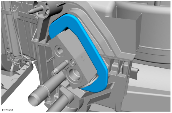
Remove the seal.
 |
-
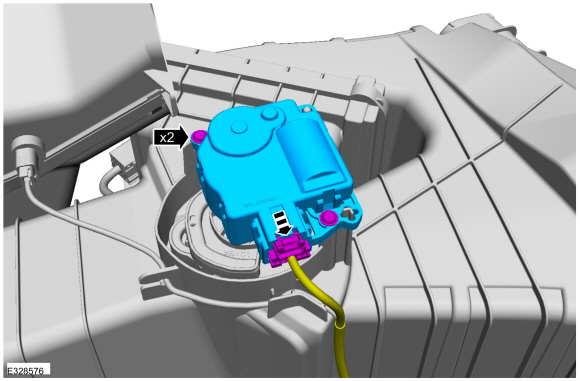
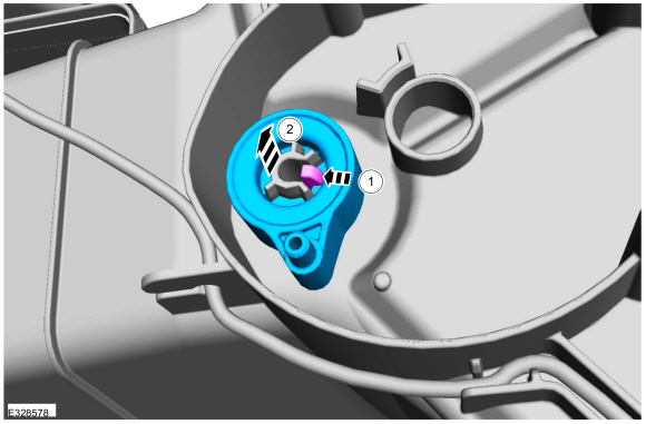
Remove the screws and the temperature door actuator.
-
Disconnect the electrical connector.
-
Disconnect the electrical connector.
 |
-
NOTE: If equipped.
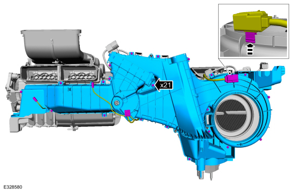
Remove the screws and the duct.
-
Disconnect the electrical connectors and position
aside the harness from the lower portion of the climate control housing.
-
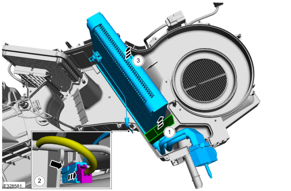
Disconnect the electrical connectors and position
aside the harness from the lower portion of the climate control housing.
 |
-
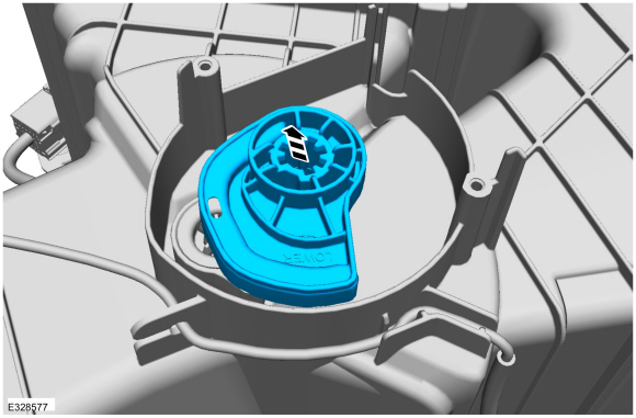
Remove the actuator cam.
 |
-
-
NOTE: Exercise caution, retainers can be easily damaged.
Depress the tempreature door lever retainer.
-
Remove the tempreature door lever.
-
 |
-
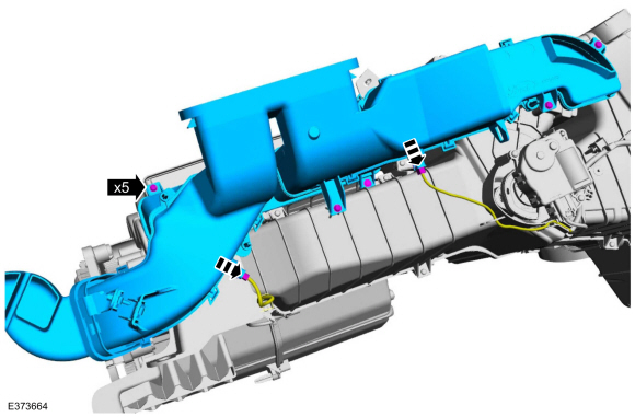
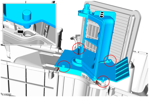
Remove the screws and the lower portion of the climate control housing.
-
Remove the harness retainer and position aside the harness.
-
Remove the harness retainer and position aside the harness.
 |
-
-
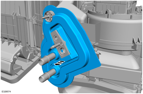
NOTE: During installation make sure the evaporator bypass support is fully seated in the climate control housing.
Remove the evaporator bypass support.
-
Disconnect the electrical connector and detach the
evaporator temperature sensor harness from the climate control housing.
-
Remove the evaporator.
-
 |
Installation
-
To install, reverse the removal procedure.
-
Make sure the divider plate dowls are properly aligned
and seated in the upper portion of the climate control housing before
installing the lower the portion of the climate control housing.
 |
-
Make sure the TXV seal is properly seated aorund the TXV
once the upper and lower portions of the climate control housing are
reassembled.
 |
 Driver Side Register Air Discharge Temperature Sensor. Removal and Installation
Special Tool(s) /
General Equipment
Interior Trim Remover
Removal
NOTE:
Removal steps in this procedure may contain installation details...
 Evaporator Temperature Sensor. Removal and Installation
Removal
NOTE:
The evaporator temperature sensor is available only as part of the evaporator assembly.
Remove the the evaporator.
Refer to: Evaporator (412-00 Climate Control System - General Information, Removal and Installation)...
Other information:
Lincoln Navigator 2018-2026 Workshop Manual: Interior Camera System. Diagnosis and Testing
Diagnostic Trouble Code (DTC) Chart Diagnostics in this manual assume a certain skill level and knowledge of Ford-specific diagnostic practices. REFER to: Diagnostic Methods (100-00 General Information, Description and Operation). Module DTC Description Action CMR B115E:49 Camera Module: Internal Electronic Failure GO to Pinpoint Test A CMR B115E:54 Cam..
Lincoln Navigator 2018-2026 Workshop Manual: Emergency Park Position Release. General Procedures
Activation NOTICE: This procedure should only be used to temporarily place the transmission in Neutral during certain service procedures when the engine cannot crank. Do not tow the vehicle on road in this mode. Failure to follow this instruction will result in transmission damage. NOTE: The following steps should be used when the engine will not crank. App..
Categories
- Manuals Home
- 4th Gen Lincoln Navigator Service Manual (2018 - 2026)
- Transmission Fluid Drain and Refill. General Procedures
- Telematics Control Unit (TCU) Module. Removal and Installation
- Identification Codes. Description and Operation
- Liftgate Trim Panel. Removal and Installation
- Body Control Module (BCM). Removal and Installation
Wheel to Hub Runout Minimization. General Procedures
Check
NOTE: Wheel-to-hub optimization is important. Clearance between the wheel and hub can be used to offset or neutralize the Road Force® or run-out of the wheel and tire assembly. For every 0.001 inch of wheel-to-hub clearance, the Road Force® can be affected between 1 and 3 pounds depending on the tire stiffness.
NOTE: The example below illustrates how the clearance between the wheel and the hub can be used to offset the high spot of radial run-out or Road Force®. Following the procedure will make sure of the best optimization.
Position the wheel and tire assembly on the vehicle so that the high spot location of radial run-out or Road Force® is at the 6 o'clock position and