Lincoln Navigator: Front Seats / Driver Front Seat Module (DSM). Removal and Installation
Removal
NOTE: DSM (driver front seat module) shown, SCMB (front passenger seat control module) is similar.
NOTE: Removal steps in this procedure may contain installation details.
All vehicles
-
NOTE: This step is only necessary when installing a new component.
NOTE: The PMI (programmable module installation) process must begin with the current DSM (driver front seat module) or SCMB (front passenger seat control module) installed. If the current DSM (driver front seat module) or SCMB (front passenger seat control module) does not respond to the diagnostic scan tool, the tool may prompt for As-Built Data as part of the repair.
Using a diagnostic scan tool, begin the PMI process for the DSM or SCMB (front passenger seat control module) following the on-screen instructions.
Vehicles with heated/ventilated seats
-
NOTE: This step is only necessary when installing a new DSM (driver front seat module).
NOTE: The SCME (front seat climate control module) is integral to the DSM (driver front seat module). PMI (programmable module installation) is required on both the DSM (driver front seat module) and the SCME (front seat climate control module) when a new DSM (driver front seat module) is installed.
NOTE: The PMI (programmable module installation) process must begin with the current SCME (front seat climate control module) installed. If the current SCME (front seat climate control module) does not respond to the diagnostic scan tool, the tool may prompt for As-Built Data as part of the repair.
Using a diagnostic scan tool, begin the PMI process for the SCME following the on-screen instructions.
-
NOTE: This step is only necessary when installing a new SCMB (passenger front seat module).
NOTE: The SCMF (rear seat climate control module) is integral to the SCMB (passenger front seat module). PMI (programmable module installation) is required on both the SCMB (passenger front seat module) and the SCMF (rear seat climate control module) when a new SCMB (passenger front seat module) is installed.
NOTE: The PMI (programmable module installation) process must begin with the current SCMF (rear seat climate control module) installed. If the current SCMF (rear seat climate control module) does not respond to the diagnostic scan tool, the tool may prompt for As-Built Data as part of the repair.
Using a diagnostic scan tool, begin the PMI process for the SCMF following the on-screen instructions.
All vehicles
-
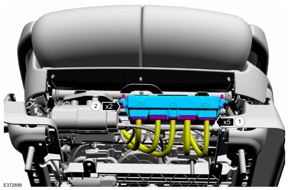
Remove the DSM .
-
Disconnect the electrical connectors
-
Remove the screws.
Torque: 44 lb.in (5 Nm)
-
Disconnect the electrical connectors
 |
Installation
All vehicles
-
To install, reverse the removal procedure.
-
NOTE: This step is only necessary when installing a new component.
Using a diagnostic scan tool, complete the PMI process for the DSM or SCMB (front passenger seat control module) following the on-screen instructions.
Vehicles with heated/ventilated seats
-
NOTE: This step is only necessary when installing a new DSM (driver front seat module).
Using a diagnostic scan tool, complete the PMI process for the SCME following the on-screen instructions.
-
NOTE: This step is only necessary when installing a new component.
Using a diagnostic scan tool, complete the PMI process for the SCMF following the on-screen instructions.
All vehicles
-
NOTE: This step is only necessary when installing a new SCMB (passenger front seat module).
Operate the seat in all directions through the full range of travel to set soft stops and avoid a premature stopping point occurrence after the vehicle is returned to the customer.
Vehicles with memory pedals
-
NOTE: This step is only necessary when installing a new component.
Operate the pedals in all directions through the full range of travel to set soft stops and avoid a premature stopping point occurrence after the vehicle is returned to the customer.
Vehicles with memory steering column
-
NOTE: This step is only necessary when installing a new component.
Use the steering column control switch to set the soft stops as followed:
-
Move the column rearward until it reaches the
end of travel and hold the switch for 2 seconds after the column has
reached the end of travel.
-
Move the column in the same direction until it
reaches the end of travel again and hold the switch for 2 seconds after
the motor has reached the end of travel. This clears any unintended soft
stops.
-
Move the column forward until it reaches the end
of travel and hold the switch for 2 seconds after the motor has reached
the end of travel.
-
Move the column in the same direction until it
reaches the end of travel and hold the switch for 2 seconds after the
motor has reached the end of travel. This clears any unintended soft
stops.
-
Repeat the sequence moving the column up and down.
-
Move the column rearward until it reaches the
end of travel and hold the switch for 2 seconds after the column has
reached the end of travel.
 Seat Heater Mat Removal. General Procedures
Repair
WARNING:
To minimize the risk of injury, always wear protective
gloves when working with a steamer. Failure to follow these instructions
may result in serious personal injury...
 Front Head Restraint. Removal and Installation
Removal
NOTE:
This procedure is for vehicles equipped with power head restraint only.
NOTE:
Drivers seat shown, passenger seat similar.
Remove the front seat...
Other information:
Lincoln Navigator 2018-2026 Workshop Manual: Keyless Entry Rear Antenna. Removal and Installation
Removal NOTE: Short wheelbase shown, long wheelbase similar. Position the liftgate weatherstrip aside. Release the clips and remove the liftgate scuff plate trim panel. Remove the load floor cover...
Lincoln Navigator 2018-2026 Workshop Manual: Third Row Single Seat Seatbelt Buckle. Removal and Installation
Removal NOTE: Removal steps in this procedure may contain installation details. Remove the third row single seat. Refer to: Third Row Seat (501-10C Third Row Seats, Removal and Installation). Remove the third row single seat seatbelt buckle...
Categories
- Manuals Home
- 4th Gen Lincoln Navigator Service Manual (2018 - 2026)
- Body Control Module (BCM). Removal and Installation
- Body and Paint
- Telematics Control Unit (TCU) Module. Removal and Installation
- Transmission Fluid Level Check. General Procedures
- Neutral Flat Tow Activation and Deactivation. General Procedures
Wheel to Hub Runout Minimization. General Procedures
Check
NOTE: Wheel-to-hub optimization is important. Clearance between the wheel and hub can be used to offset or neutralize the Road Force® or run-out of the wheel and tire assembly. For every 0.001 inch of wheel-to-hub clearance, the Road Force® can be affected between 1 and 3 pounds depending on the tire stiffness.
NOTE: The example below illustrates how the clearance between the wheel and the hub can be used to offset the high spot of radial run-out or Road Force®. Following the procedure will make sure of the best optimization.
Position the wheel and tire assembly on the vehicle so that the high spot location of radial run-out or Road Force® is at the 6 o'clock position and