Lincoln Navigator: Rear Drive Axle/Differential - Vehicles With: Ford 9.75 Inch Ring Gear / Drive Pinion Flange. Removal and Installation
Special Tool(s) / General Equipment
 |
205-126
(T78P-4851-A)
Holding Fixture, Drive Pinion Flange |
 |
205-233
(T85T-4851-AH)
Installer, Drive Pinion Flange TKIT-1985-FH-1 |
| Three Leg Puller | |
| Cable Ties | |
| Punch | |
Materials
| Name | Specification |
|---|---|
| Motorcraft® Premium Long-Life Grease XG-1-E1 |
ESA-M1C75-B |
| Retaining Compound Loctite® 638™ |
WSK-M2G349-A8 |
Removal
NOTICE: This operation disturbs the pinion bearing preload. Carefully reset the pinion bearing preload during installation or damage to the component may occur.
-
NOTE: Remove the rear wheel and tire assemblies, brake calipers and brake discs to prevent brake drag during the drive pinion bearing preload adjustment.
Remove the rear brake disc.
Refer to: Brake Disc (206-04 Rear Disc Brake, Removal and Installation).
-
Remove the rear stabilizer bar.
Refer to: Rear Stabilizer Bar (204-02 Rear Suspension, Removal and Installation).
-
-
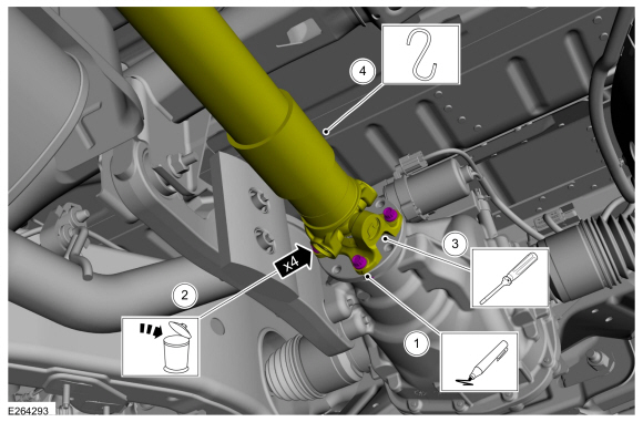
Index mark the driveshaft and the pinion flange for reference during installation.
-
Remove and discard the driveshaft to pinion flange bolts.
Torque: 76 lb.ft (103 Nm)
-
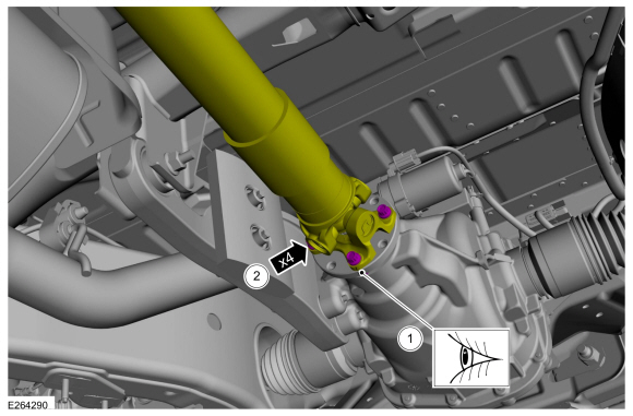
NOTICE: The driveshaft flange fits tightly on the flange pilot. Never hammer on the driveshaft or any of its components to disconnect the driveshaft flange from the flange pilot. Pry only in the area shown with a suitable tool, to disconnect the driveshaft flange from the flange pilot or damage to the driveshaft flange can occur.
Separate the driveshaft flange from the pinion flange and support the driveshaft.
Use the General Equipment: Punch
-
Support the driveshaft.
Use the General Equipment: Cable Ties
-
Index mark the driveshaft and the pinion flange for reference during installation.
 |
-
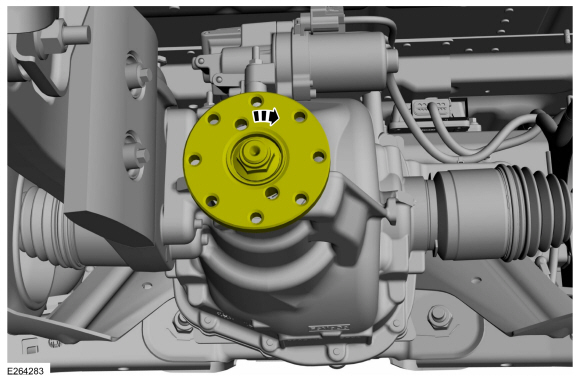
NOTE: Rotational torque of the drive pinion flange must be measured and recorded using a Nm (lb-in) torque wrench for correct pinion bearing preload when reassembled. This will be the torque-to-turn measurement.
Using a dial type torque wrench, measure and record the rotational torque of the drive pinion.
 |
-
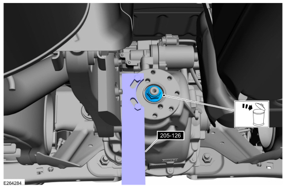
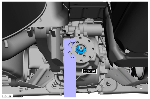
NOTICE: Install a new pinion nut with the same color as the original if not replacing the collapsible spacer. If a new collapsible spacer is installed, install the nut in the kit or damage to the component may occur.
Using the special tool to hold the pinion flange, remove and discard the pinion nut.
Use Special Service Tool: 205-126 (T78P-4851-A) Holding Fixture, Drive Pinion Flange.
 |
-
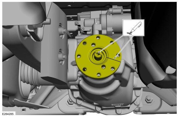
Index mark the drive pinion flange and the drive pinion stem for reassembly.
 |
-
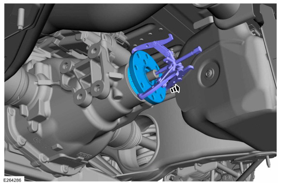
Using the general equipment, remove the pinion flange.
Use the General Equipment: Three Leg Puller
 |
-
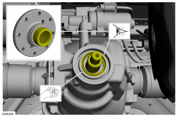
Clean and inspect the pinion flange mating surfaces and pinion seal surface.
 |
Installation
-
If necessary.
Install a new drive pinion seal.
Refer to: Drive Pinion Seal (205-02 Rear Drive Axle/Differential - Vehicles With: Ford 9.75 Inch Ring Gear, Removal and Installation).
-
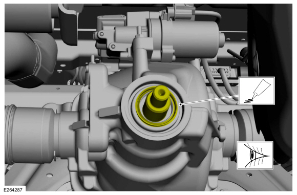
Lubricate the drive pinion flange mating surface and seal lip with grease.
Material: Motorcraft® Premium Long-Life Grease / XG-1-E1 (ESA-M1C75-B)
 |
-
Disregard the index marks if installing a new drive pinion flange.
 |
-
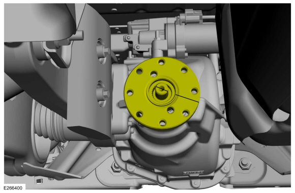
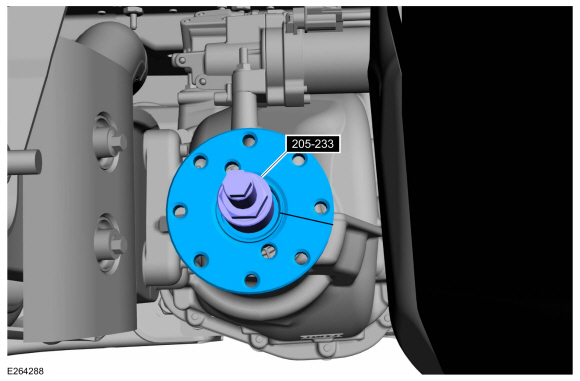
NOTE: Make sure drive pinion flange and drive pinion stem are phased correctly using previously applied mark.
Using the special tool, install the pinion flange.
Use Special Service Tool: 205-233 (T85T-4851-AH) Installer, Drive Pinion Flange.
 |
-
NOTICE: Under no circumstances is the pinion nut to be backed off to reduce drive pinion bearing preload. If reduced drive pinion bearing preload is required, a new drive pinion collapsible spacer and pinion nut must be installed or damage to the component may occur.
NOTE: When installing the drive pinion flange and pinion nut with no differential carrier installed, the drag torque (torque to turn) should be 2 to 3 Nm (16-29 in-lbs).
NOTE: Refer to the rotational torque previously recorded with the Nm (lb-in) torque wrench. Tighten the pinion nut in small increments until it is within 0.3 Nm (3 lb-in) of the reference measurement. If 0.3 Nm (3 lb-in) is exceeded, then the collapsible spacer will be damaged and a new collapsible spacer will be required.
NOTE: Apply loctite on the pinion shaft threads before installing the nut.
Using the special tool to hold the pinion 2WD flange, install the new pinion nut.
Use Special Service Tool: 205-126 (T78P-4851-A) Holding Fixture, Drive Pinion Flange.
Material: Retaining Compound / Loctite® 638™ (WSK-M2G349-A8)
 |
-
-
Align the index-mark on the driveshaft to the rear axle pinion flange.
-
Install the new driveshaft-to-pinion flange bolts.
Torque: 76 lb.ft (103 Nm)
-
Align the index-mark on the driveshaft to the rear axle pinion flange.
 |
-
Install the rear stabilizer bar.
Refer to: Rear Stabilizer Bar (204-02 Rear Suspension, Removal and Installation).
-
Check the differential fluid level.
Refer to: Differential Fluid Level Check (205-02 Rear Drive Axle/Differential - Vehicles With: Ford 9.75 Inch Ring Gear, General Procedures).
-
Install the rear brake disc.
Refer to: Brake Disc (206-04 Rear Disc Brake, Removal and Installation).

 Drive Pinion Seal. Removal and Installation
Special Tool(s) /
General Equipment
205-208
(T83T-4676-A)
Installer, Drive Pinion Oil SealTKIT-1983-FTKIT-1983-FLMTKIT-1983-FX
Flat-Bladed Screwdriver
Materials
Name
Specification
Motorcraft® Premium Long-Life GreaseXG-1-E1
ESA-M1C75-B
Removal
Remove the drive pinion flange...
Other information:
Lincoln Navigator 2018-2026 Workshop Manual: Rear View Mirrors - Overview. Description and Operation
Overview Exterior, Power The power mirror system allows the LH and RH exterior mirror glass to be positioned electronically. The movement of the exterior mirror glass is controlled by the exterior mirror control switch and the LH or RH mirror selection buttons determine which exterior mirror glass is controlled...
Lincoln Navigator 2018-2026 Workshop Manual: Information and Entertainment System - Component Location. Description and Operation
NOTE: The available speaker configurations are shown first. The remaining hidden audio and SYNC system components and various cable routings follow the speaker configurations. NOTE: Some vehicles may not be equipped with all the optional components shown...
Categories
- Manuals Home
- 4th Gen Lincoln Navigator Service Manual (2018 - 2026)
- Telematics Control Unit (TCU) Module. Removal and Installation
- Liftgate Trim Panel. Removal and Installation
- Rear Bumper. Removal and Installation
- Front Bumper Cover. Removal and Installation
- Vehicle Dynamics Control Module (VDM). Removal and Installation
Rear Drive Axle and Differential. Diagnosis and Testing
Symptom Chart(s)
Diagnostics in this manual assume a certain skill level and knowledge of Ford-specific diagnostic practices.
REFER to: Diagnostic Methods (100-00 General Information, Description and Operation).
Symptom Chart - Differential
Symptom Chart - Differential
Condition Actions Axle overheating GO to Pinpoint Test A Broken gear teeth on the ring gear or pinion GO to Pi