
Lincoln Navigator: Front End Body Panels / Cowl Panel. Removal and Installation
Removal
NOTE: Removal steps in this procedure may contain installation details.
-
Remove the cowl panel grille.
Refer to: Cowl Panel Grille (501-02 Front End Body Panels, Removal and Installation).
-
Remove the LH cowl panel.
-
Remove the screw.
Torque: 28 lb.in (3.2 Nm)
-
Remove the push pins and the LH cowl panel.
-
Remove the screw.
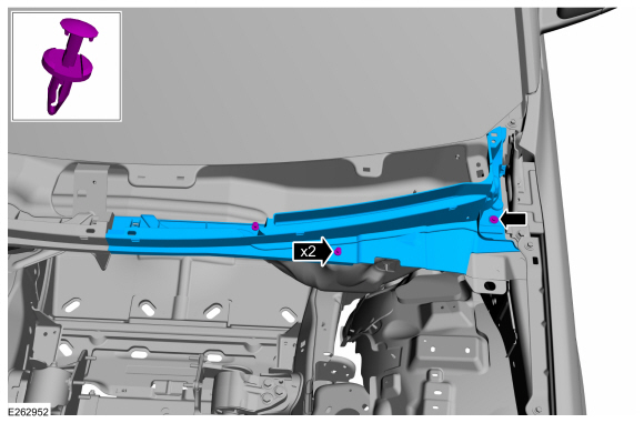 |
-
Remove the RH cowl panel.
-
Remove the screw.
Torque: 28 lb.in (3.2 Nm)
-
Remove the push pins and the RH cowl panel.
-
Remove the screw.
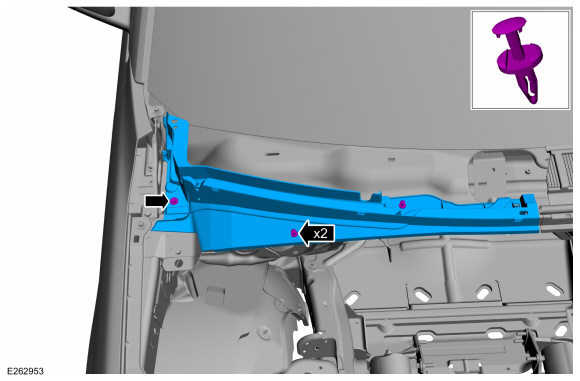 |
Installation
-
To install, reverse the removal procedure.
 Active Grille Shutter Actuator. Removal and Installation
Removal
Upper active grille shutter actuator
Remove the upper active grille shutter.
Refer to: Active Grille Shutter (501-02 Front End Body Panels, Removal and Installation)...
 Cowl Panel Grille. Removal and Installation
Removal
Both sides
Remove the wiper pivot arm.
Refer to: Windshield Wiper Pivot Arm (501-16 Wipers and Washers, Removal and Installation)...
Other information:
Lincoln Navigator 2018-2026 Workshop Manual: Front Door Window Glass. Removal and Installation
Removal NOTE: LH side shown, RH side similar. Remove the front door glass top run. Refer to: Front Door Glass Top Run (501-11 Glass, Frames and Mechanisms, Removal and Installation). Remove the front door glass...
Lincoln Navigator 2018-2026 Workshop Manual: Rear Bumper Cover. Disassembly and Assembly
Special Tool(s) / General Equipment Electric Drill DISASSEMBLY NOTE: Disassembly steps in this procedure may contain assembly details. Remove the rear bumper cover. Refer to: Rear Bumper Cover (501-19 Bumpers, Removal and Installation)...
Categories
- Manuals Home
- 4th Gen Lincoln Navigator Service Manual (2018 - 2026)
- Body and Paint
- Identification Codes. Description and Operation
- Transmission Fluid Drain and Refill. General Procedures
- Windshield Washer Pump. Removal and Installation
- Neutral Flat Tow Activation and Deactivation. General Procedures
Wheel to Hub Runout Minimization. General Procedures
Check
NOTE: Wheel-to-hub optimization is important. Clearance between the wheel and hub can be used to offset or neutralize the Road Force® or run-out of the wheel and tire assembly. For every 0.001 inch of wheel-to-hub clearance, the Road Force® can be affected between 1 and 3 pounds depending on the tire stiffness.
NOTE: The example below illustrates how the clearance between the wheel and the hub can be used to offset the high spot of radial run-out or Road Force®. Following the procedure will make sure of the best optimization.
Position the wheel and tire assembly on the vehicle so that the high spot location of radial run-out or Road Force® is at the 6 o'clock position and