Lincoln Navigator: Engine System - General Information / Valve Train Analysis. General Procedures
Valve Train Analysis - Engine Off, Valve Cover Removed
NOTE: The following component inspections are used to diagnose valve train concerns.
-
Check for damaged or severely worn parts and correct assembly.
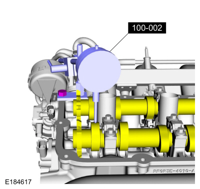
Valve Train Analysis - Camshaft Lobe Lift
-
Remove the spark plugs.
For additional information, refer to: Spark Plugs (303-07 Engine Ignition - 3.5L EcoBoost (272kW/370PS), Removal and Installation).
For additional information, refer to: Spark Plugs (303-07 Engine Ignition - 3.5L EcoBoost (272kW/370PS), Removal and Installation).
For additional information, refer to: Spark Plugs (303-07 Engine Ignition - 3.5L EcoBoost (272kW/370PS), Removal and Installation).
For additional information, refer to: Spark Plugs (303-07 Engine Ignition - 3.5L EcoBoost (272kW/370PS), Removal and Installation).
For additional information, refer to: Spark Plugs (303-07 Engine Ignition - 3.5L EcoBoost (272kW/370PS), Removal and Installation).
-
Install the Dial Indicator Gauge with Holding Fixture so
the rounded tip of the dial indicator is on top of the camshaft lobe
and on the same plane as the valve tappet.
 |
-
Rotate the crankshaft using a breaker bar and socket
attached to the crankshaft pulley retainer bolt. Rotate the crankshaft
until the base circle of the camshaft lobe is reached.
-
Zero the dial indicator. Continue to rotate the
crankshaft until the high-lift point of the camshaft lobe is in the
fully raised position (highest indicator reading).
-
To check the accuracy of the original dial indicator
reading, continue to rotate crankshaft until the base circle is reached.
The indicator reading should be zero. If zero reading is not obtained,
repeat Steps 2 through 5.
-
If the lift on any lobe is below specified service
limits, install a new camshaft and camshaft roller followers or valve
tappets.
-
Install the spark plugs.
For additional information, refer to: Spark Plugs (303-07 Engine Ignition - 3.5L EcoBoost (272kW/370PS), Removal and Installation).
For additional information, refer to: Spark Plugs (303-07 Engine Ignition - 3.5L EcoBoost (272kW/370PS), Removal and Installation).
For additional information, refer to: Spark Plugs (303-07 Engine Ignition - 3.5L EcoBoost (272kW/370PS), Removal and Installation).
For additional information, refer to: Spark Plugs (303-07 Engine Ignition - 3.5L EcoBoost (272kW/370PS), Removal and Installation).
For additional information, refer to: Spark Plugs (303-07 Engine Ignition - 3.5L EcoBoost (272kW/370PS), Removal and Installation).
 Valve Stem Diameter. General Procedures
Check
NOTE:
Refer to the appropriate Section 303-01 for the specification.
Measure the diameter of each intake and exhaust valve
stem at the points shown...

Other information:
Lincoln Navigator 2018-2026 Workshop Manual: Shock Absorber and Spring Assembly. Disassembly and Assembly
Special Tool(s) / General Equipment Spring Compressor Vise DISASSEMBLY NOTICE: Suspension fasteners are critical parts that affect the performance of vital components and systems. Failure of these fasteners may result in major service expense. Use the same or equivalent parts if replacement is necessary. Do not use a replacement part of lesser quality or s..
Lincoln Navigator 2018-2026 Workshop Manual: Body Repair Health and Safety and General Precautions. Description and Operation
WARNING: Always refer to Material Safety Data Sheet (MSDS) when handling chemicals and wear protective equipment as directed. Examples may include but are not limited to respirators and chemically resistant gloves. Failure to follow these instructions may result in serious personal injury. WARNING: Always wear protective equipment including eye protection w..
Categories
- Manuals Home
- 4th Gen Lincoln Navigator Service Manual (2018 - 2026)
- Identification Codes. Description and Operation
- Body Control Module (BCM). Removal and Installation
- Rear View Mirrors - System Operation and Component Description. Description and Operation
- Transmission Fluid Drain and Refill. General Procedures
- Power Running Board (PRB). Diagnosis and Testing
Front Driveshaft. Removal and Installation
Special Tool(s) / General Equipment
Crimping ToolMaterials
Name Specification Motorcraft® Premium Long-Life GreaseXG-1-E1 ESA-M1C75-B
Removal
With the vehicle in NEUTRAL, position the vehicle on a hoist.Refer to: Jacking and Lifting (100-02 Jacking and Lifting, Description and Operation).
Remove the bolts and the transmission shield.