Lincoln Navigator: Third Row Seats / Third Row Double Seat Frame. Removal and Installation
Removal
 WARNING:
The following procedure describes critical repair steps
required for correct seat component installation. Follow all notes and
steps carefully. Do not place any objects between the seat components
and the body of the vehicle, nor any objects within a joint internal to
the seat structure. Failure to follow step instructions may result in
incorrect operation of the seat components and increases the risk of
serious personal injury.
WARNING:
The following procedure describes critical repair steps
required for correct seat component installation. Follow all notes and
steps carefully. Do not place any objects between the seat components
and the body of the vehicle, nor any objects within a joint internal to
the seat structure. Failure to follow step instructions may result in
incorrect operation of the seat components and increases the risk of
serious personal injury.
NOTE: Removal steps in this procedure may contain installation details.
-
Remove the third double row seat.
Refer to: Third Row Seat (501-10C Third Row Seats, Removal and Installation).
-
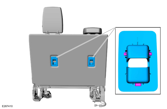
Remove the child safety seat tether anchor bezels.
 |
-
-
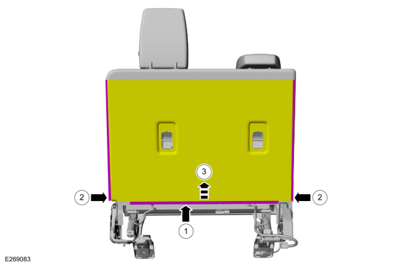
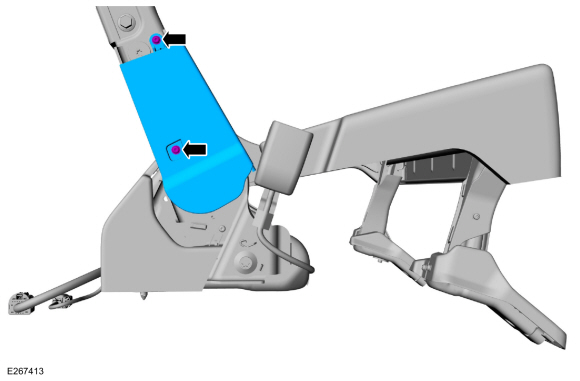
Release the third row double seat backrest cover the J-clip.
-
Unzip the third row double seat backrest cover.
-
Position the third row double seat backrest cover flap aside.
-
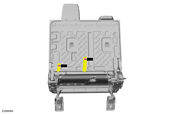
Release the third row double seat backrest cover the J-clip.
 |
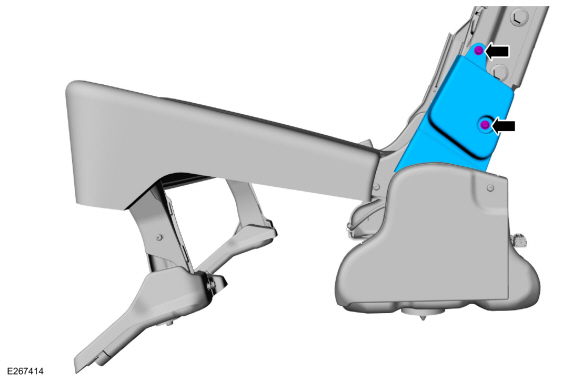
-
Remove the pin-type retainers and position the third row double seat backrest cover straps aside.
 |
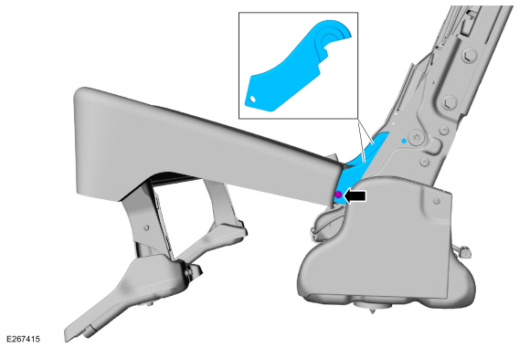
-
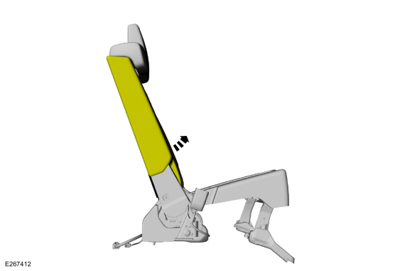
Lift the third row double seat backrest cover.
 |
-
Remove the screws and the third row double seat RH side shield.
 |
-
Remove the screws and the third row double seat LH side shield.
 |
-
On both sides.
Remove the screws and the third row double seat pivot arm covers.
 |
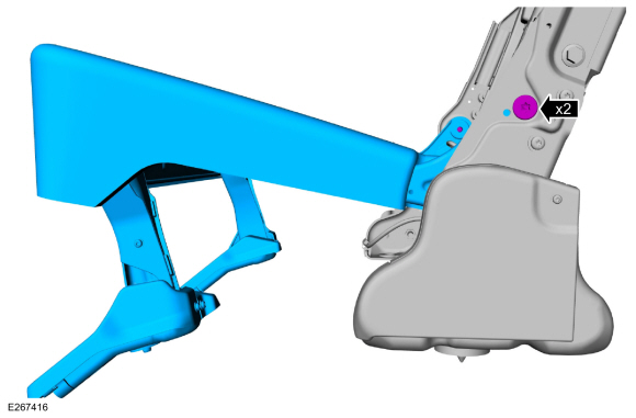
-
Remove the bolts and the third row double seat frame.
Torque: 33 lb.ft (45 Nm)
 |
-
NOTE: This step is only necessary when installing a new component.
Remove the third row double seat cushion cover.
Refer to: Third Row Double Seat Cushion Cover (501-10C Third Row Seats, Removal and Installation).
Installation
-
NOTE: Transfer components to the new third row double seat frame as necessary.
To install, reverse the removal procedures.
 Third Row Double Seat Cushion Cover. Removal and Installation
Removal
Remove the third row double seat.
Refer to: Third Row Seat (501-10C Third Row Seats, Removal and Installation).
Detach the third row double seat cushion cover J-clips...
 Third Row Seat. Removal and Installation
Removal
WARNING:
The following procedure describes critical repair steps
required for correct seat component installation. Follow all notes and
steps carefully...
Other information:
Lincoln Navigator 2018-2026 Workshop Manual: E Clutch. Description and Operation
Overview Item Description 1 SSE 2 E clutch control valve 3 Clutch gain control valve 4 E clutch apply circuit 5 E clutch piston 6 E clutch assembly 7 Shell and sun gear..
Lincoln Navigator 2018-2026 Workshop Manual: Transmission Internal Wiring Harness. Removal and Installation
Special Tool(s) / General Equipment 307-746Remover, Transmission Wiring Harness Connector Removal Remove the main control valve body. Refer to: Main Control Valve Body (307-01 Automatic Transmission - 10-Speed Automatic Transmission – 10R80, Removal and Installation). Main Control Valve Body Harness Disconnect the internal ..
Categories
- Manuals Home
- 4th Gen Lincoln Navigator Service Manual (2018 - 2026)
- SYNC Module [APIM]. Removal and Installation
- Windshield Washer Pump. Removal and Installation
- Head Up Display (HUD) Module Calibration. General Procedures
- Transmission Fluid Drain and Refill. General Procedures
- Vehicle Dynamics Control Module (VDM). Removal and Installation
Wheel to Hub Runout Minimization. General Procedures
Check
NOTE: Wheel-to-hub optimization is important. Clearance between the wheel and hub can be used to offset or neutralize the Road Force® or run-out of the wheel and tire assembly. For every 0.001 inch of wheel-to-hub clearance, the Road Force® can be affected between 1 and 3 pounds depending on the tire stiffness.
NOTE: The example below illustrates how the clearance between the wheel and the hub can be used to offset the high spot of radial run-out or Road Force®. Following the procedure will make sure of the best optimization.
Position the wheel and tire assembly on the vehicle so that the high spot location of radial run-out or Road Force® is at the 6 o'clock position and