Lincoln Navigator: Steering Wheel and Column Electrical Components / Steering Column Control Module (SCCM). Removal and Installation
Removal
NOTE: Removal steps in this procedure may contain installation details.
-
NOTE: This step is only necessary when installing a new component.
NOTE: The PMI process must begin with the current SCCM installed. If the current SCCM does not respond to the diagnostic scan tool, the tool may prompt for As-Built data as part of the repair.
Using a diagnostic scan tool, begin the PMI process for the SCCM following the on-screen instructions.
-
Remove the clockspring.
Refer to: Clockspring (501-20B Supplemental Restraint System, Removal and Installation).
-
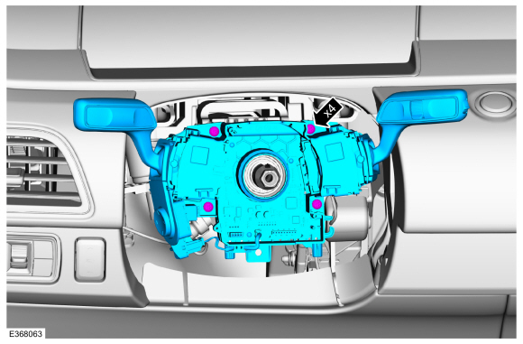
Disconnect the SCCM electrical connectors, unclip the pin type retainer and position the harness aside.
 |
-
Remove the retainers and the SCCM .
Torque: 28 lb.in (3.2 Nm)
 |
Installation
-
To install, reverse the removal procedure.
-
NOTE: This step is only necessary when installing a new component.
Using a diagnostic scan tool, complete the PMI process for the SCCM following the on-screen instructions.
 Steering Wheel and Column Electrical Components. Diagnosis and Testing
Diagnostic Trouble Code (DTC) Chart
Diagnostics in this manual assume a certain skill level and knowledge of Ford-specific diagnostic practices. REFER to: Diagnostic Methods (100-00 General Information, Description and Operation)...
 Steering Column Control Switch. Removal and Installation
Removal
NOTE:
Removal steps in this procedure may contain installation details.
Remove the steering column shrouds.
Refer to: Steering Column Shrouds (501-05 Interior Trim and Ornamentation, Removal and Installation)...
Other information:
Lincoln Navigator 2018-2026 Workshop Manual: Climate Control System - System Operation and Component Description. Description and Operation
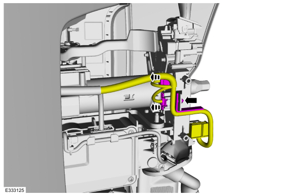
System Operation System Diagram E371291 *.sttxt { visibility: hidden; } *.stcallout { visibility: visible; } 1 GWM 2 Cabin heater coolant pump 3 Externally Controlled Variable Dsiplacement Compressor (EVDC) ..
Lincoln Navigator 2018-2026 Workshop Manual: Telematics Control Unit (TCU) Module Antenna. Removal and Installation
Removal NOTE: Removal steps in this procedure may contain installation details. Remove the instrument panel. Refer to: Instrument Panel (501-12 Instrument Panel and Console, Removal and Installation). Remove the bolts, separate the wire harness guide, disconnect and remove the TCU antenna. Torque: 71 lb.in (8 Nm) ..
Categories
- Manuals Home
- 4th Gen Lincoln Navigator Service Manual (2018 - 2026)
- Vehicle Dynamics Control Module (VDM). Removal and Installation
- Neutral Flat Tow Activation and Deactivation. General Procedures
- Head Up Display (HUD) Module Calibration. General Procedures
- Transmission Fluid Level Check. General Procedures
- SYNC Module [APIM]. Removal and Installation
Differential Case Runout Check. General Procedures
Special Tool(s) / General Equipment
 205-1016
Installer, Differential Bearing
TKIT-2014D-ROW2
TKIT-2014D-FL_ROW
 205-153
(T80T-4000-W)
205-153
(T80T-4000-W)
Handle
 205-D061
(D83T-4205-C2)
205-D061
(D83T-4205-C2)
Step Plate Dial Indicator Three Leg Puller Punch