Lincoln Navigator: Front Suspension - LHD 4WD / Shock Absorber and Spring Assembly. Removal and Installation
Special Tool(s) / General Equipment
 |
204-592 Separator, Lower Arm Ball Joint TKIT-2006C-FFMFLM TKIT-2006C-LM TKIT-2006C-ROW |
| Spring Compressor | |
| Tie Rod End Remover | |
Removal
NOTICE: Suspension fasteners are critical parts that affect the performance of vital components and systems. Failure of these fasteners may result in major service expense. Use the same or equivalent parts if replacement is necessary. Do not use a replacement part of lesser quality or substitute design. Tighten fasteners as specified.
-
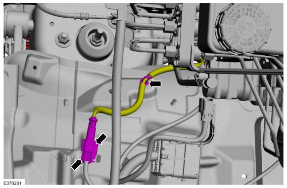
NOTE: The wheel speed sensor electrical connector is located in the engine compartment secured to the fender apron.
Disconnect the wheel speed sensor electrical connector and detach the harness retainer.
 |
-
Remove the brake disc shield.
Refer to: Brake Disc Shield (206-03 Front Disc Brake, Removal and Installation).
-
-
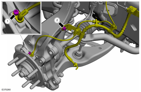
Remove the wheel speed sensor wire bracket bolt.
-
Remove the wheel speed sensor wire bracket bolt on
the wheel knuckle and position aside the wheel speed sensor wire.
-
Remove the wheel speed sensor wire bracket bolt.
 |
-
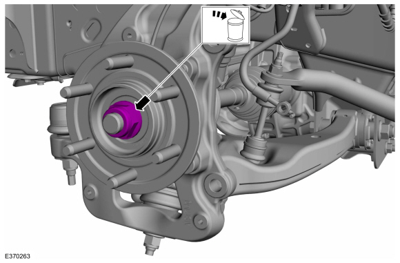
Remove and discard the wheel hub nut.
 |
-
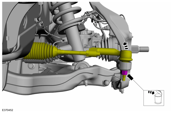
NOTICE: Do not use a hammer to separate the outer tie-rod end from the wheel knuckle or damage to the wheel knuckle may result.
NOTICE: Use care when installing the tie rod separator or damage to the outer tie-rod end boot may occur.
NOTE: Use the hex-holding feature to prevent the stud from turning while removing the nut.
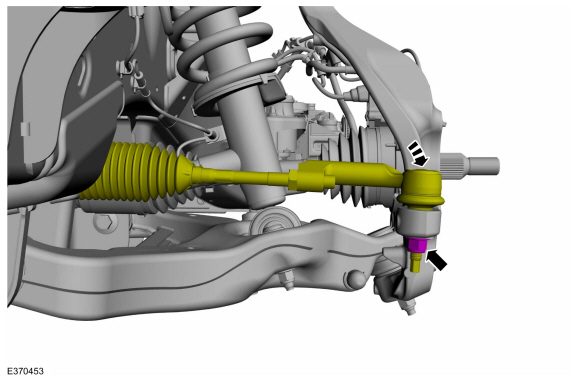
Remove and discard the tie rod end nut and separate the tie rod end from the wheel knuckle.
Use the General Equipment: Tie Rod End Remover
 |
-
Remove the IWE bolts.
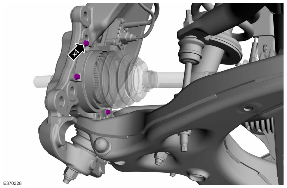 |
-
Position the IWE and halfshaft.
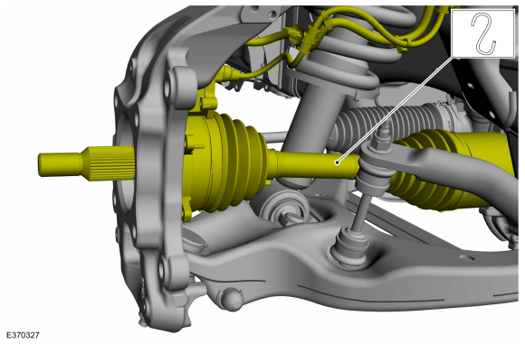 |
-
NOTICE: The suspension height sensors must be disconnected prior to servicing suspension components. Damage to the suspension height sensors and/or the vehicle dynamic suspension system may occur. The sensors will need to be recalibrated after reassembly.
NOTE: If equipped with dynamic suspension.
Remove the height sensor arm bracket screw and position aside the bracket.
 |
-
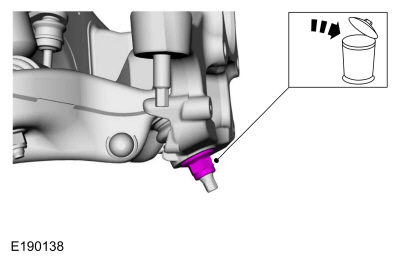
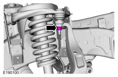
Remove and discard the upper ball joint nut.
 |
-
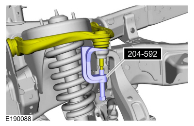
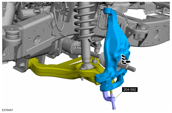
NOTE: Be sure not to damage the ball joint boot when installing the Ball Joint Separator.
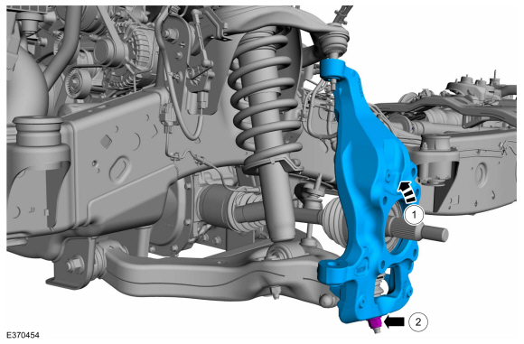
Separate the upper ball joint from the wheel knuckle.
Use Special Service Tool: 204-592 Separator, Lower Arm Ball Joint.
 |
-
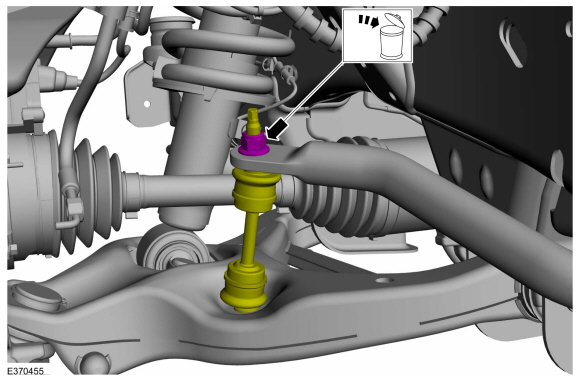
Remove and discard the lower ball joint nut.
 |
-
NOTICE: Do not use a prying device or separator fork between the ball joint and the wheel knuckle. Damage to the ball joint or ball joint seal may result.
NOTICE: Use care when releasing the lower arm and wheel knuckle into the resting position or damage to the ball joint seal may occur.
Separate the wheel knuckle from the lower ball joint and remove the wheel knuckle.
Use Special Service Tool: 204-592 Separator, Lower Arm Ball Joint.
 |
-
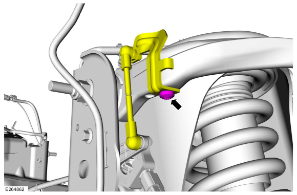
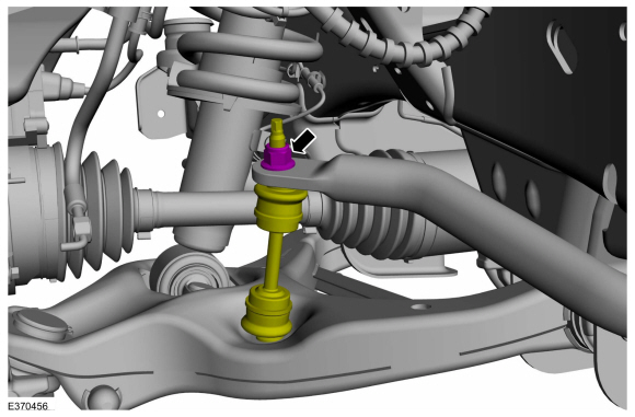
NOTICE: Do not use power tools to remove or install the stabilizer bar link nuts. Damage to the stabilizer bar link ball joints and boots may occur.
NOTE: The stabilizer bar links are designed with low friction ball joints that have a low breakaway torque.
NOTE: Use the hex-holding feature to prevent the ball stud from turning while removing or installing the stabilizer bar link nut.
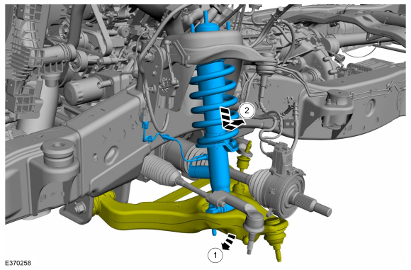
Remove and discard the front stabilizer bar link upper nut.
 |
-
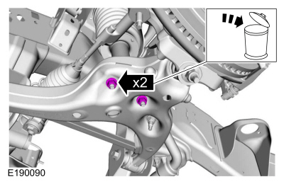
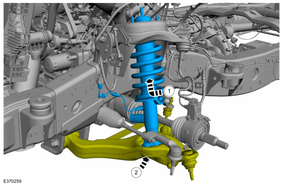
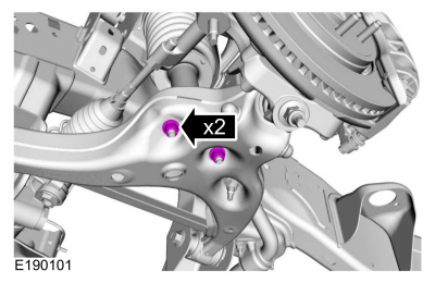
Remove and discard the shock absorber and spring assembly lower nuts.
 |
-
NOTE: If equipped with dynamic suspension.
NOTE: RH side only.
-
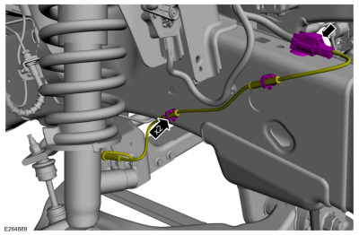
Disconnect the shock absorber and spring assembly electrical connector from the RH side frame.
-
Disconnect the shock absorber and spring assembly wiring harness clips from the frame and position aside.
-
Disconnect the shock absorber and spring assembly electrical connector from the RH side frame.
 |
-
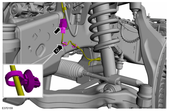
NOTE: If equipped with dynamic suspension.
NOTE: LH side only.
Disconnect the shock absorber and spring assembly electric connector and wiring harness clips.
 |
-
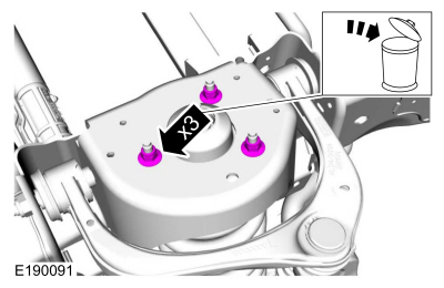
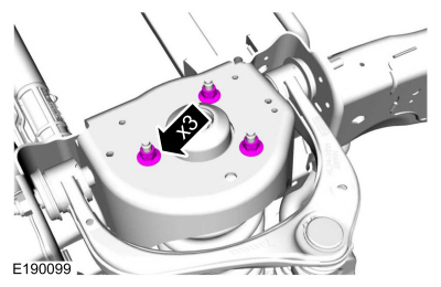
Remove and discard the shock absorber and spring assembly upper nuts.
 |
-
-
Position the lower arm down to gain clearance for removing the shock absorber and spring assembly.
-
Remove the shock absorber and spring assembly.
-
Position the lower arm down to gain clearance for removing the shock absorber and spring assembly.
 |
-
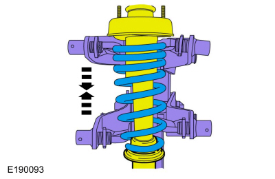
NOTE: If the individual spring and/or shock components are not being serviced, continue to the installation procedure.
NOTE: For reference during assembly, index the upper mount, spring and shock absorber.
Compress the spring until the tension is released from the shock absorber.
Use the General Equipment: Spring Compressor
 |
-
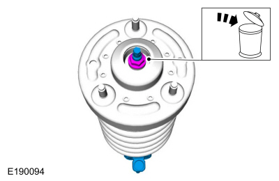
NOTE: Use the hex-holding feature to prevent the shock rod from turning while removing the nut.
Remove and discard the shock rod nut.
 |
-
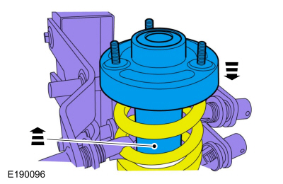
Remove the upper mount and the shock absorber from the spring.
Use the General Equipment: Spring Compressor
 |
Installation
-
Install the shock absorber and the upper mount.
Use the General Equipment: Spring Compressor
 |
-
NOTE: If the individual spring and/or shock components are not being serviced, continue to the installation procedure.
NOTE: For reference during assembly, index the upper mount, spring and shock absorber.
Compress the spring until the tension is released from the shock absorber.
Use the General Equipment: Spring Compressor
|
-
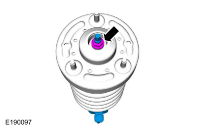
NOTE: Use the hex-holding feature to prevent the shock rod from turning while installing the nut.
While holding the shock rod, install the new shock absorber and the shock rod nut.
Torque: 41 lb.ft (56 Nm)
 |
-
-
Install the shock absorber and spring assembly.
-
Position the lower arm up.
-
Install the shock absorber and spring assembly.
 |
-
Install the new shock absorber and spring assembly upper nuts.
Torque: 46 lb.ft (63 Nm)
 |
-
Install the new shock absorber and spring assembly lower nuts.
Torque: 66 lb.ft (90 Nm)
 |
-
NOTICE: Do not use power tools to remove or install the stabilizer bar link nuts. Damage to the stabilizer bar link ball joints and boots may occur.
NOTE: The stabilizer bar links are designed with low friction ball joints that have a low breakaway torque.
NOTE: Use the hex-holding feature to prevent the ball stud from turning while removing or installing the stabilizer bar link nut.
Install the new front stabilizer link upper nut.
Torque: 59 lb.ft (80 Nm)
 |
-
-
Install the wheel knuckle.
-
Install the new lower ball joint nut.
Torque: 76 lb.ft (103 Nm)
-
Install the wheel knuckle.
 |
-
Install the new upper ball joint nut.
Torque: 46 lb.ft (63 Nm)
 |
-
NOTICE: The suspension height sensors must be disconnected prior to servicing suspension components. Damage to the suspension height sensors and/or the vehicle dynamic suspension system may occur. The sensors will need to be recalibrated after reassembly.
NOTE: If equipped with dynamic suspension.
Position the height sensor arm bracket and install the height sensor arm bracket screw.
Torque: 177 lb.in (20 Nm)
|
-
Install the IWE bolts.
Torque: 106 lb.in (12 Nm)
|
-
NOTICE: Do not use a hammer to separate the outer tie-rod end from the wheel knuckle or damage to the wheel knuckle may result.
NOTICE: Use care when installing the tie rod separator or damage to the outer tie-rod end boot may occur.
NOTE: Use the hex-holding feature to prevent the stud from turning while installing the nut.
Position the tie rod end and install the new tie rod end nut.
Torque: 76 lb.ft (103 Nm)
 |
-
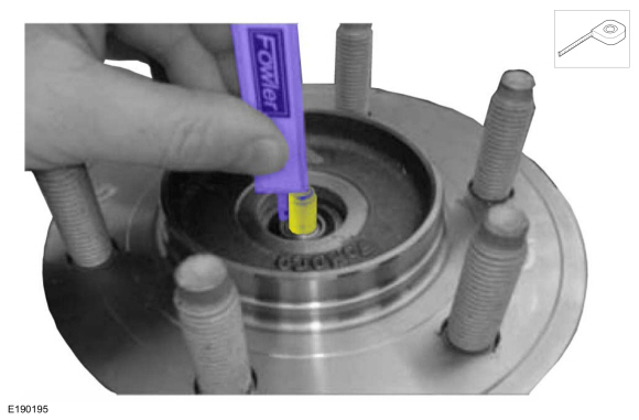
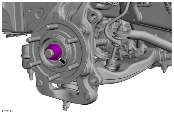
NOTICE: Measure the depth of the CV shaft threaded end to the inner bearing race (shown in illustration). The minimum depth is 15.5 mm (0.61 in). If the depth is less than 15.5 mm (0.61 in) rotate the CV shaft to clear a binding condition between the IWE and CV splines. Installing the axle nut and tightening without the proper depth of protrusion will result in damage to the IWE .
Measure the CV shaft threaded end to the inner bearing race.
 |
-
-
Install the new the axle nut.
Torque: 184 lb.ft (250 Nm)
-
Verify wheel hub to IWE engagement. The wheel hub and IWE should rotate together.
-
Install the new the axle nut.
 |
-
-
Position the wheel speed sensor wire and install the wheel speed sensor wire bracket bolt.
Torque: 106 lb.in (12 Nm)
-
Install the wheel speed sensor wire bracket bolt on the wheel knuckle.
Torque: 18 lb.ft (25 Nm)
-
Position the wheel speed sensor wire and install the wheel speed sensor wire bracket bolt.
|
-
NOTE: The wheel speed sensor electrical connector is located in the engine compartment secured to the fender apron.
Connect the wheel speed sensor electrical connector and the harness retainer.
|
-
Install the brake disc.
Refer to: Brake Disc Shield (206-03 Front Disc Brake, Removal and Installation).
-
NOTE: If equipped with dynamic suspension.
NOTE: RH side only.
-
Connect the shock absorber and spring assembly electrical connector on the RH side frame.
-
Position the shock absorber and spring assembly
wiring harness and connect the wiring harness clips into the frame.
-
Connect the shock absorber and spring assembly electrical connector on the RH side frame.
|
-
NOTE: If equipped with dynamic suspension.
NOTE: LH side only.
Connect the shock absorber and spring assembly electrical connector and wiring harness clips.
|
-
Install the wheel and tire.
Refer to: Wheel and Tire (204-04A Wheels and Tires, Removal and Installation).
- If equipped with dynamic suspension, calibrate the suspension height sensor. Connect the scan tool and carry out the Ride Height Calibration routine. Follow the scan tool directions.
 Lower Ball Joint. Removal and Installation
Special Tool(s) /
General Equipment
204-358Remover/Installer, Ball JointTKIT-2005P-FTKIT-2005P-ROW
205-086
(T74P-4635-C)
Installer/Remover, C-Frame and Screw
Removal
Remove the wheel knuckle...
 Upper Arm. Removal and Installation
Removal
NOTICE:
Suspension fasteners are critical parts that affect the
performance of vital components and systems. Failure of these fasteners
may result in major service expense...
Other information:
Lincoln Navigator 2018-2026 Workshop Manual: Pyrotechnic Device Health and Safety Precautions. Description and Operation
WARNING: Service and handling of Pyrotechnic Components is restricted to qualified personnel. The required qualifications vary by region. Always observe local laws and legislative directives regarding Pyrotechnic Components service and handling...
Lincoln Navigator 2018-2026 Workshop Manual: Rear Door Speaker. Removal and Installation
Removal NOTE: Removal steps in this procedure may contain installation details. All door speakers Remove the rear door trim panel. Refer to: Rear Door Trim Panel (501-05 Interior Trim and Ornamentation, Removal and Installation)...
Categories
- Manuals Home
- 4th Gen Lincoln Navigator Service Manual (2018 - 2026)
- Head Up Display (HUD) Module Calibration. General Procedures
- Rear Bumper. Removal and Installation
- Body and Paint
- Body Control Module (BCM). Removal and Installation
- Liftgate Trim Panel. Removal and Installation
Differential Case Runout Check. General Procedures
Special Tool(s) / General Equipment
 205-1016
Installer, Differential Bearing
TKIT-2014D-ROW2
TKIT-2014D-FL_ROW
 205-153
(T80T-4000-W)
205-153
(T80T-4000-W)
Handle
 205-D061
(D83T-4205-C2)
205-D061
(D83T-4205-C2)
Step Plate Dial Indicator Three Leg Puller Punch