• Navigator Manuals
  • Service
  • New
  • Top
  • Sitemap
Lincoln Navigator Manuals

Lincoln Navigator: Rear View Mirrors / Rear View Mirrors. Diagnosis and Testing

Lincoln Navigator 2018-2025 Workshop Manual / Body and Paint / Rear View Mirrors / Rear View Mirrors. Diagnosis and Testing

Diagnostic Trouble Code (DTC) Chart

Diagnostics in this manual assume a certain skill level and knowledge of Ford-specific diagnostic practices.
REFER to: Diagnostic Methods (100-00 General Information, Description and Operation).


Module DTC Description Action
DDM B1163:11 Left Mirror Heater Output: Circuit Short To Ground GO to Pinpoint Test D
DDM B1163:15 Left Mirror Heater Output: Circuit Short To Battery Or Open GO to Pinpoint Test D
DDM B1163:4B Left Mirror Heater Output: Over Temperature GO to Pinpoint Test D
DDM B11F6:11 Driver Folding Mirror Motor: Circuit Short To Ground GO to Pinpoint Test E
DDM B11F6:15 Driver Folding Mirror Motor: Circuit Short To Battery Or Open GO to Pinpoint Test E
DDM B1C09:11 Driver Left/Right Mirror Motor: Circuit Short To Ground GO to Pinpoint Test B
DDM B1C10:11 Driver Up/Down Mirror Motor: Circuit Short To Ground GO to Pinpoint Test B
DDM B1C13:11 Driver Up/Down Mirror Motor Feedback: Circuit Short To Ground GO to Pinpoint Test C
DDM B1C13:15 Driver Up/Down Mirror Motor Feedback: Circuit Short To Battery Or Open GO to Pinpoint Test C
DDM B1C14:11 Driver Left/Right Mirror Motor Feedback: Circuit Short To Ground GO to Pinpoint Test C
DDM B1C14:15 Driver Left/Right Mirror Motor Feedback: Circuit Short To Battery Or Open GO to Pinpoint Test C
DDM C1B15:11 Sensor Supply Voltage B: Circuit Short To Ground GO to Pinpoint Test C
DDM C1B15:15 Sensor Supply Voltage B: Circuit Short To Battery Or Open GO to Pinpoint Test C
PDM B1164:11 Right Mirror Heater Output: Circuit Short To Ground GO to Pinpoint Test D
PDM B1164:15 Right Mirror Heater Output: Circuit Short To Battery Or Open GO to Pinpoint Test D
PDM B1164:4B Right Mirror Heater Output: Over Temperature GO to Pinpoint Test D
PDM B11F7:11 Passenger Folding Mirror Motor: Circuit Short To Ground GO to Pinpoint Test E
PDM B11F7:15 Passenger Folding Mirror Motor: Circuit Short To Battery Or Open GO to Pinpoint Test E
PDM B1C11:11 Passenger Left/Right Mirror Motor: Circuit Short To Ground GO to Pinpoint Test B
PDM B1C12:11 Passenger Up/Down Mirror Motor: Circuit Short To Ground GO to Pinpoint Test B
PDM B1C15:11 Passenger Up/Down Mirror Motor Feedback: Circuit Short To Ground GO to Pinpoint Test C
PDM B1C15:15 Passenger Up/Down Mirror Motor Feedback: Circuit Short To Battery Or Open GO to Pinpoint Test C
PDM B1C16:11 Passenger Left/Right Mirror Motor Feedback: Circuit Short To Ground GO to Pinpoint Test C
PDM B1C16:15 Passenger Left/Right Mirror Motor Feedback: Circuit Short To Battery Or Open GO to Pinpoint Test C
PDM C1B15:11 Sensor Supply Voltage B: Circuit Short To Ground GO to Pinpoint Test C
PDM C1B15:15 Sensor Supply Voltage B: Circuit Short To Battery Or Open GO to Pinpoint Test C

Global Customer Symptom Code (GCSC) Chart

Diagnostics in this manual assume a certain skill level and knowledge of Ford-specific diagnostic practices.
REFER to: Diagnostic Methods (100-00 General Information, Description and Operation).


Symptom Action
Driver Aid & Information > Blind Spot (BLIS)/Cross Traffic > Controls > Inoperative GO to Pinpoint Test M
Lighting/Glass/Vision > Mirror > Rear View > Appearance GO to Pinpoint Test N
Lighting/Glass/Vision > Mirror > Rear View > Inoperative GO to Pinpoint Test J
Lighting/Glass/Vision > Mirror > Rear View > Inoperative GO to Pinpoint Test N
Lighting/Glass/Vision > Mirror > Rear View > Loose/Attachment GO to Pinpoint Test O
Lighting/Glass/Vision > Mirror > Side > Appearance GO to Pinpoint Test G
Lighting/Glass/Vision > Mirror > Side > Appearance GO to Pinpoint Test H
Lighting/Glass/Vision > Mirror > Side > Appearance GO to Pinpoint Test I
Lighting/Glass/Vision > Mirror > Side > Inoperative GO to Pinpoint Test H
Lighting/Glass/Vision > Mirror > Side > Inoperative GO to Pinpoint Test J
Lighting/Glass/Vision > Mirror > Side > Loose/Attachment GO to Pinpoint Test G
Lighting/Glass/Vision > Mirror > Side > Loose/Attachment GO to Pinpoint Test P
Lighting/Glass/Vision > Mirror > Side > Loose/Attachment GO to Pinpoint Test Q
Lighting/Glass/Vision > Mirror > Side > Loose/Attachment GO to Pinpoint Test R
Lighting/Glass/Vision > Mirror > Side > Manual Function GO to Pinpoint Test G
Lighting/Glass/Vision > Defrost > Mirror > Inoperative GO to Pinpoint Test I
Lighting/Glass/Vision > Exterior Lighting > Turn Signal > Inoperative GO to Pinpoint Test L
Lighting/Glass/Vision > Exterior Lighting > Turn Signal > Stays On GO to Pinpoint Test L
Lighting/Glass/Vision > Exterior Lighting > Puddle > Inoperative GO to Pinpoint Test K
Lighting/Glass/Vision > Exterior Lighting > Puddle > Stays On GO to Pinpoint Test K
Lighting/Glass/Vision > Noise > Mirror > Always GO to Pinpoint Test R
Lighting/Glass/Vision > Noise > Mirror > Intermittent GO to Pinpoint Test R

DTC Chart: DDM

Diagnostics in this manual assume a certain skill level and knowledge of Ford-specific diagnostic practices.
REFER to: Diagnostic Methods (100-00 General Information, Description and Operation).

Module DTC Description Action
  DDM B11F6:11 Driver Folding Mirror Motor: Circuit Short To Ground   GO to Pinpoint Test E
  DDM B11F6:15 Driver Folding Mirror Motor: Circuit Short To Battery or Open   GO to Pinpoint Test E
  DDM B1163:11 Left Mirror Heater Output: Circuit Short To Ground   GO to Pinpoint Test D
  DDM B1163:15 Left Mirror Heater Output: Circuit Short To Battery Or Open   GO to Pinpoint Test D
  DDM B1C09:11 Driver Left/Right Mirror Motor: Circuit Short To Ground   GO to Pinpoint Test B
  DDM B1C09:15 Driver Left/Right Mirror Motor: Circuit Short To Battery Or Open   GO to Pinpoint Test B
  DDM B1C10:11 Driver Up/Down Mirror Motor: Circuit Short To Ground   GO to Pinpoint Test C
  DDM B1C10:15 Driver Up/Down Mirror Motor: Circuit Short To Battery Or Open   GO to Pinpoint Test C
  DDM B1C13:11 Driver Up/Down Mirror Motor Feedback: Circuit Short To Ground   GO to Pinpoint Test C
  DDM B1C13:15 Driver Up/Down Mirror Motor Feedback: Circuit Short To Battery Or Open   GO to Pinpoint Test C
  DDM B1C14:11 Driver Left/Right Mirror Motor Feedback: Circuit Short To Ground   GO to Pinpoint Test C
  DDM B1C14:15 Driver Left/Right Mirror Motor Feedback: Circuit Short To Battery Or Open   GO to Pinpoint Test C
  DDM C1B15:11 Sensor Supply Voltage B: Circuit Short To Ground   GO to Pinpoint Test C
  DDM C1B15:15 Sensor Supply Voltage B: Circuit Short To Battery or Open   GO to Pinpoint Test C
  DDM All other DDM Diagnostic Trouble Codes (DTCs) -  
REFER to: Locks, Latches and Entry Systems (501-14 Handles, Locks, Latches and Entry Systems, Diagnosis and Testing).

DTC Chart: PDM

Diagnostics in this manual assume a certain skill level and knowledge of Ford-specific diagnostic practices.
REFER to: Diagnostic Methods (100-00 General Information, Description and Operation).

Module DTC Description Action
  PDM B11F7:11 Passenger Folding Mirror Motor: Circuit Short To Ground   GO to Pinpoint Test E
  PDM B11F7:15 Passenger Folding Mirror Motor: Circuit Short To Battery or Open   GO to Pinpoint Test E
  PDM B1164:11 Right Mirror Heater Output: Circuit Short To Ground   GO to Pinpoint Test D
  PDM B1164:15 Right Mirror Heater Output: Circuit Short To Battery Or Open   GO to Pinpoint Test D
  PDM B1C11:11 Passenger Left/Right Mirror Motor: Circuit Short To Ground   GO to Pinpoint Test B
  PDM B1C11:15 Passenger Left/Right Mirror Motor: Circuit Short To Battery Or Open   GO to Pinpoint Test B
  PDM B1C12:11 Passenger Up/Down Mirror Motor: Circuit Short To Ground   GO to Pinpoint Test B
  PDM B1C12:15 Passenger Up/Down Mirror Motor: Circuit Short To Battery Or Open   GO to Pinpoint Test B
  PDM B1C15:11 Passenger Up/Down Mirror Motor Feedback: Circuit Short To Ground   GO to Pinpoint Test C
  PDM B1C15:15 Passenger Up/Down Mirror Motor Feedback: Circuit Short To Battery Or Open   GO to Pinpoint Test C
  PDM B1C16:11 Passenger Left/Right Mirror Motor Feedback: Circuit Short To Ground   GO to Pinpoint Test C
  PDM B1C16:15 Passenger Left/Right Mirror Motor Feedback: Circuit Short To Battery Or Open   GO to Pinpoint Test C
  PDM C1B15:11 Sensor Supply Voltage B: Circuit Short To Ground   GO to Pinpoint Test C
  PDM C1B15:15 Sensor Supply Voltage B: Circuit Short To Battery or Open   GO to Pinpoint Test C
  PDM All other PDM Diagnostic Trouble Codes (DTCs) -  
REFER to: Locks, Latches and Entry Systems (501-14 Handles, Locks, Latches and Entry Systems, Diagnosis and Testing).

Symptom Chart(s)

Symptom Chart: Rear View Mirrors - Exterior

Diagnostics in this manual assume a certain skill level and knowledge of Ford-specific diagnostic practices.
REFER to: Diagnostic Methods (100-00 General Information, Description and Operation).

NOTE: Clean the entire mirror assembly and glass to assist in verification of the customer concern and/or impact damage. Do not clean any mirror glass or housing with an ice scraper, razor blade, abrasive pad, harsh chemicals or petroleum based cleaning products, as these may damage the mirror glass and/or housing.

Condition Action
One or both exterior mirrors fold inward due to wind pressure   GO to Pinpoint Test G
Both exterior mirrors are inoperative (with or without memory mirrors)   GO to Pinpoint Test H
A single mirror is inoperative/does not operate correctly   GO to Pinpoint Test A
A single mirror horizontal or vertical operation does not function correctly   GO to Pinpoint Test B
The exterior mirror memory recall feature is inoperative/does not operate correctly   GO to Pinpoint Test C
One or both heated exterior mirrors are inoperative or always on   GO to Pinpoint Test D
The LH and RH heated exterior mirrors do not defrost at the same rate   GO to Pinpoint Test I
The LH auto-dimming exterior mirror is inoperative or always in a darkened state   GO to Pinpoint Test F
An exterior mirror selection switch LED is inoperative (exterior mirror selection switch functions normally)   GO to Pinpoint Test J
The exterior mirror puddle lamp is inoperative or always on   GO to Pinpoint Test K
The exterior mirror turn signal is inoperative or always on   GO to Pinpoint Test L
The BLIS ® indicator is inoperative or always on   GO to Pinpoint Test M

Symptom Chart: Rear View Mirrors - Interior

Diagnostics in this manual assume a certain skill level and knowledge of Ford-specific diagnostic practices.
REFER to: Diagnostic Methods (100-00 General Information, Description and Operation).

NOTE: Clean the entire mirror assembly and glass to assist in verification of the customer concern and/or impact damage. Do not clean any mirror glass or housing with an ice scraper, razor blade, abrasive pad, harsh chemicals or petroleum based cleaning products, as these may damage the mirror glass and/or housing.

Condition Action
The interior mirror is blemished   GO to Pinpoint Test N
The interior mirror vibrates or is loose   GO to Pinpoint Test O
The interior auto-dimming mirror does not operate correctly   GO to Pinpoint Test S

Symptom Chart: Rear View Mirrors - Exterior Noise, Vibration and Harshness (NVH)

Diagnostics in this manual assume a certain skill level and knowledge of Ford-specific diagnostic practices.
REFER to: Diagnostic Methods (100-00 General Information, Description and Operation).

NOTE: Clean the entire mirror assembly and glass to assist in verification of the customer concern and/or impact damage. Do not clean any mirror glass or housing with an ice scraper, razor blade, abrasive pad, harsh chemicals or petroleum based cleaning products, as these may damage the mirror glass and/or housing.

Condition Action
Exterior mirror housing vibrates or is loose   GO to Pinpoint Test P
Exterior mirror glass vibrates or is loose   GO to Pinpoint Test Q
Wind noise   GO to Pinpoint Test R

Pinpoint Tests

A Single Mirror Is Inoperative/Does Not Operate Correctly


Refer to Wiring Diagrams Cell 124 for schematic and connector information.

Normal Operation and Fault Conditions


REFER to: Rear View Mirrors - System Operation and Component Description (501-09 Rear View Mirrors, Description and Operation).

Possible Causes

  • Wiring, terminals or connectors
  • Power window concern
  • Exterior mirror control switch (integral to the LH front window control switch)
  • Exterior mirror motor
  • Exterior mirror

Visual Inspection and Diagnostic Pre-Checks

  • Inspect the suspect exterior mirror for damage or obstructions.

NOTE: Clean the entire mirror assembly and glass to assist in verification of the customer concern and/or impact damage. Do not clean any mirror glass or housing with an ice scraper, razor blade, abrasive pad, harsh chemicals or petroleum based cleaning products, as these may damage the mirror glass and/or housing.


PINPOINT TEST A: A SINGLE MIRROR IS INOPERATIVE/DOES NOT OPERATE CORRECTLY

NOTE: Clean the entire mirror assembly and glass to assist in verification of the customer concern and/or impact damage. Do not clean any mirror glass or housing with an ice scraper, razor blade, abrasive pad, harsh chemicals or petroleum based cleaning products, as these may damage the mirror glass and/or housing.


Refer to Wiring Diagrams Cell 124 for schematic and connector information.

Normal Operation and Fault Conditions

REFER to: Rear View Mirrors - System Operation and Component Description (501-09 Rear View Mirrors, Description and Operation).

Possible Sources

  • Wiring, terminals or connectors
  • Power window concern
  • Exterior mirror control switch (integral to the LH front window control switch)
  • Exterior mirror motor
  • Exterior mirror

Visual Inspection and Pre-checks

  • Inspect the suspect exterior mirror for damage or obstructions.

NOTICE: Use the correct probe adapter(s) when making measurements. Failure to use the correct probe adapter(s) may cause damage to the connector. Use only Rotunda Flex Probes (NUD105-R025D)

A1 CHECK THE EXTERIOR MIRROR CONTROL SWITCH PARAMETER IDENTIFICATIONS (PIDS)
  • Using a diagnostic scan tool, view the DDM Parameter Identifications (PIDs).
  • Using a diagnostic scan tool, view the following DDM mirror control switch Parameter Identifications (PIDs):
    • L_MIR_SEL
    • R_MIR_SEL
    • MIR_SW_DOWN
    • MIR_SW_UP
    • MIR_SW_L
    • MIR_SW_R
  • While monitoring the Parameter Identifications (PIDs), switch the mirror control switch to the left mirror and press each directional control switch.
  • While monitoring the Parameter Identifications (PIDs), switch the mirror control switch to the right mirror and press each directional control switch.

Do the Parameter Identifications (PIDs) agree with the mirror control switch presses?
Yes GO to A2
No INSTALL a new LH front door window control switch.
REFER to: Driver Door Window Control Switch (501-11 Glass, Frames and Mechanisms, Removal and Installation).

A2 CHECK THE SUSPECT EXTERIOR MIRROR MOTOR COMMON CIRCUIT FOR AN OPEN
  • Ignition OFF.
  • Disconnect: Suspect Exterior Mirror C516 (LH concern) or C622 (RH concern).
  • Disconnect: DDM C501B (LH concern) or PDM C652B (RH concern).
  • Measure:
    Click to display connectors

      LH


    Positive Lead Measurement / Action Negative Lead
      C501B-21   C516-4

    Click to display connectors

      RH


    Positive Lead Measurement / Action Negative Lead
      C652B-21   C622-4

Is the resistance less than 3 ohms?
Yes GO to A3
No REPAIR the circuit.

A3 CHECK THE EXTERIOR MIRROR JUMPER HARNESS
  • Inspect the exterior mirror jumper harness between the vehicle harness and the mirror motors for:
    • Open or short circuits
    • Damaged or pushed out pins
    • Corrosion

Is the harness OK?
Yes INSTALL a new exterior mirror motor for the one in question.
REFER to: Exterior Mirror (501-09 Rear View Mirrors, Removal and Installation).
No REPAIR the harness as necessary. If the harness cannot be repaired, INSTALL a new exterior mirror.
REFER to: Exterior Mirror (501-09 Rear View Mirrors, Removal and Installation).

PINPOINT TEST B: A SINGLE MIRROR HORIZONTAL OR VERTICAL OPERATION DOES NOT FUNCTION CORRECTLY

NOTE: Clean the entire mirror assembly and glass to assist in verification of the customer concern and/or impact damage. Do not clean any mirror glass or housing with an ice scraper, razor blade, abrasive pad, harsh chemicals or petroleum based cleaning products, as these may damage the mirror glass and/or housing.


Refer to Wiring Diagrams Cell 124 for schematic and connector information.

Normal Operation and Fault Conditions

REFER to: Rear View Mirrors - System Operation and Component Description (501-09 Rear View Mirrors, Description and Operation).

DTC Fault Trigger Conditions

DTC Description Fault Trigger Condition
DDM B1C09:11 Driver Left/Right Mirror Motor: Circuit Short To Ground A continuous and on-demand DTC that sets in the DDM if the DDM detects a higher than expected current draw when voltage is applied to the horizontal mirror motor circuit.
DDM B1C10:11 Driver Up/Down Mirror Motor: Circuit Short To Ground A continuous and on-demand DTC that sets in the DDM if the DDM detects a higher than expected current draw when voltage is applied to the vertical mirror motor circuit.
PDM B1C11:11 Passenger Left/Right Mirror Motor: Circuit Short To Ground A continuous and on-demand DTC that sets in the PDM if the PDM detects a higher than expected current draw when voltage is applied to the horizontal mirror motor circuit.
PDM B1C12:11 Passenger Up/Down Mirror Motor: Circuit Short To Ground A continuous memory DTC that sets in the PDM if the PDM detects a higher than expected current draw when voltage is applied to the vertical mirror motor circuit.

Possible Sources

  • Wiring, terminals or connectors
  • Exterior mirror control switch (integral to the LH front window control switch)
  • Power mirror system concern
  • Exterior mirror motor
  • Exterior mirror
  • DDM
  • PDM

Visual Inspection and Pre-checks

  • Inspect the suspect exterior mirror for damage or obstructions.

NOTICE: Use the correct probe adapter(s) when making measurements. Failure to use the correct probe adapter(s) may cause damage to the connector. Use only Rotunda Flex Probes (NUD105-R025D)

B1 CHECK THE MIRROR MOVEMENT
  • Ignition ON.
  • Operate the suspect exterior mirror in the up, down, left and right directions.

Does the suspect exterior mirror operate in any direction?
Yes GO to B2
No GO to Pinpoint Test A

B2 CHECK THE EXTERIOR MIRROR CONTROL SWITCH PARAMETER IDENTIFICATIONS (PIDS)
  • Using a diagnostic scan tool, view the DDM Parameter Identifications (PIDs).
  • Using a diagnostic scan tool, view the following DDM mirror control switch Parameter Identifications (PIDs):
    • L_MIR_SEL
    • R_MIR_SEL
    • MIR_SW_DOWN
    • MIR_SW_UP
    • MIR_SW_L
    • MIR_SW_R
  • While monitoring the Parameter Identifications (PIDs), press the left mirror selection switch and press each directional control switch.
  • While monitoring the Parameter Identifications (PIDs), press the right mirror selection switch and press each directional control switch.

Do the Parameter Identifications (PIDs) agree with the mirror control switch presses?
Yes GO to B3
No INSTALL a new LH front door window control switch.
REFER to: Driver Door Window Control Switch (501-11 Glass, Frames and Mechanisms, Removal and Installation).

B3 CHECK THE VOLTAGE OUTPUT TO THE SUSPECT EXTERIOR MIRROR

NOTICE: The following step uses a test lamp to simulate normal circuit loads. Use only a Rotunda Test Lamp (SGT27000) or 250-300mA incandescent bulb test lamp. To avoid connector terminal damage, use the Rotunda Flex Probe kit for the test lamp probe connection to the vehicle. Do not use the test lamp probe directly on any connector.

  • Ignition OFF.
  • Disconnect: Suspect Exterior Mirror C516 (LH concern) or C622 (RH concern).
  • Ignition ON.
  • Select the suspect exterior mirror by pressing the appropriate exterior mirror selection switch.
  • Connect:
    Click to display connectors

      LH


    Lead 1 Measurement / Action Lead 2
      C516-5   Ground
      C516-4   Ground

    Click to display connectors

      RH


    Lead 1 Measurement / Action Lead 2
      C622-5   Ground
      C622-4   Ground
  • Press the exterior mirror control switch in the left/right directions and monitor the test lamp.
  • Connect:
    Click to display connectors

      LH


    Lead 1 Measurement / Action Lead 2
      C516-3   Ground
      C516-4   Ground

    Click to display connectors

      RH


    Lead 1 Measurement / Action Lead 2
      C622-3   Ground
      C622-4   Ground
  • Press the exterior mirror control switch in the up/down directions and monitor the test lamp.

Does the test lamp illuminate only when the exterior mirror control switch is pressed in each direction?
Yes GO to B4
No GO to B5

B4 CHECK THE EXTERIOR MIRROR JUMPER HARNESS
  • Inspect the exterior mirror jumper harness between the vehicle harness and the mirror motors for:
    • Open or short circuits
    • Damaged or pushed out pins
    • Corrosion

Is the harness OK?
Yes INSTALL a new exterior mirror motor in question.
REFER to: Exterior Mirror (501-09 Rear View Mirrors, Removal and Installation).
No REPAIR the harness as necessary. If the harness cannot be repaired, INSTALL a new exterior mirror.
REFER to: Exterior Mirror (501-09 Rear View Mirrors, Removal and Installation).

B5 CHECK THE SUSPECT EXTERIOR MIRROR CIRCUITS FOR A SHORT TO VOLTAGE
  • Ignition OFF.
  • Disconnect: DDM C501B (LH concern) or PDM C652B (RH concern).
  • Ignition ON.
  • Measure:
    Click to display connectors

      LH


    Positive Lead Measurement / Action Negative Lead
      C516-5   Ground
      C516-4   Ground
      C516-3   Ground

    Click to display connectors

      RH


    Positive Lead Measurement / Action Negative Lead
      C622-5   Ground
      C622-4   Ground
      C622-3   Ground

Is any voltage present?
Yes REPAIR the circuit in question.
No GO to B6

B6 CHECK THE SUSPECT EXTERIOR MIRROR CIRCUITS FOR A SHORT TO GROUND
  • Ignition OFF.
  • Measure:
    Click to display connectors

      LH


    Positive Lead Measurement / Action Negative Lead
      C516-5   Ground
      C516-4   Ground
      C516-3   Ground

    Click to display connectors

      RH


    Positive Lead Measurement / Action Negative Lead
      C622-5   Ground
      C622-4   Ground
      C622-3   Ground

Are the resistances greater than 10,000 ohms?
Yes GO to B7
No REPAIR the circuit in question.

B7 CHECK THE SUSPECT EXTERIOR MIRROR CIRCUITS FOR AN OPEN
  • Measure:
    Click to display connectors

      LH


    Positive Lead Measurement / Action Negative Lead
      C516-5   C501B-10
      C516-4   C501B-21
      C516-3   C501B-9

    Click to display connectors

      RH


    Positive Lead Measurement / Action Negative Lead
      C622-5   C652B-10
      C622-4   C652B-21
      C622-3   C652B-9

Are the resistances less than 3 ohms?
Yes GO to B8
No REPAIR the circuit in question.

B8 CHECK FOR CORRECT DDM (DRIVER DOOR MODULE) / PDM (PASSENGER DOOR MODULE) OPERATION
  • Disconnect and inspect all DDM / PDM connectors and related in-line connectors.
  • Repair:
    • corrosion (install new connector or terminals - clean module pins)
    • damaged or bent pins - install new terminals/pins
    • pushed-out pins - install new pins as necessary
  • Reconnect the DDM / PDM connectors and related in-line connectors. Make sure they seat and latch correctly.
  • Operate the system to determine if the concern is still present.

Is the concern still present?
Yes CHECK OASIS for any applicable Technical Service Bulletins (TSBs). If a TSB exists for this concern, DISCONTINUE this test and FOLLOW the TSB instructions. If no Technical Service Bulletins (TSBs) address this concern, INSTALL a new DDM / PDM .
REFER to: Driver Door Module (DDM) (419-10 Multifunction Electronic Modules, Removal and Installation).
REFER to: Passenger Door Module (PDM) (419-10 Multifunction Electronic Modules, Removal and Installation).
No The system is operating correctly at this time. The concern may have been caused by module connections. ADDRESS the root cause of any connector or pin issues.

PINPOINT TEST C: THE EXTERIOR MIRROR MEMORY RECALL FEATURE IS INOPERATIVE/DOES NOT OPERATE CORRECTLY

NOTE: Clean the entire mirror assembly and glass to assist in verification of the customer concern and/or impact damage. Do not clean any mirror glass or housing with an ice scraper, razor blade, abrasive pad, harsh chemicals or petroleum based cleaning products, as these may damage the mirror glass and/or housing.

NOTE: If the DDM or PDM detects a mirror motor feedback circuit fault, a timeout strategy disables the memory operations for 30 seconds to prevent system damage. After the 30 seconds timeout, normal operation resumes.


Refer to Wiring Diagrams Cell 124 for schematic and connector information.

Normal Operation and Fault Conditions

REFER to: Rear View Mirrors - System Operation and Component Description (501-09 Rear View Mirrors, Description and Operation).

DTC Fault Trigger Conditions

DTC Description Fault Trigger Condition
DDM B1C13:11 Driver Up/Down Mirror Motor Feedback: Circuit Short To Ground A continuous and on-demand DTC that sets in the DDM if the DDM detects a short to ground from the vertical position feedback circuit.
DDM B1C13:15 Driver Up/Down Mirror Motor Feedback: Circuit Short To Battery Or Open A continuous and on-demand DTC that sets in the DDM if the DDM detects a short to voltage or open from the vertical position feedback circuit.
DDM B1C14:11 Driver Left/Right Mirror Motor Feedback: Circuit Short To Ground A continuous and on-demand DTC that sets in the DDM if the DDM detects a short to ground from the horizontal position feedback circuit.
DDM B1C14:15 Driver Left/Right Mirror Motor Feedback: Circuit Short To Battery Or Open A continuous and on-demand DTC that sets in the DDM if the DDM detects a short to voltage or open from the horizontal position feedback circuit.
DDM C1B15:11 Sensor Supply Voltage B: Circuit Short To Ground A continuous and on-demand DTC that sets in the DDM / PDM if the DDM / PDM detects a short to ground from the exterior mirror position sensor voltage supply circuit.
DDM C1B15:15 Sensor Supply Voltage B: Circuit Short To Battery Or Open A continuous and on-demand DTC that sets in the DDM / PDM if the DDM / PDM detects a short to voltage or open from the exterior mirror position sensor voltage supply circuit.
PDM B1C15:11 Passenger Up/Down Mirror Motor Feedback: Circuit Short To Ground A continuous and on-demand DTC that sets in the PDM if the PDM detects a short to ground from the vertical position feedback circuit.
PDM B1C15:15 Passenger Up/Down Mirror Motor Feedback: Circuit Short To Battery Or Open A continuous and on-demand DTC that sets in the PDM if the PDM detects a short to voltage or open from the vertical position feedback circuit.
PDM B1C16:11 Passenger Left/Right Mirror Motor Feedback: Circuit Short To Ground A continuous and on-demand DTC that sets in the PDM if the PDM detects a short to ground from the horizontal position feedback circuit.
PDM B1C16:15 Passenger Left/Right Mirror Motor Feedback: Circuit Short To Battery Or Open A continuous and on-demand DTC that sets in the PDM if the PDM detects a short to voltage or open from the horizontal position feedback circuit.
PDM C1B15:11 Sensor Supply Voltage B: Circuit Short To Ground A continuous and on-demand DTC that sets in the DDM / PDM if the DDM / PDM detects a short to ground from the exterior mirror position sensor voltage supply circuit.
PDM C1B15:15 Sensor Supply Voltage B: Circuit Short To Battery Or Open A continuous and on-demand DTC that sets in the DDM / PDM if the DDM / PDM detects a short to voltage or open from the exterior mirror position sensor voltage supply circuit.

Possible Sources

  • Wiring, terminals or connectors
  • Memory seat system concern
  • Power mirror system concern
  • Exterior mirror motor
  • Exterior mirror
  • DDM
  • PDM

NOTICE: Use the correct probe adapter(s) when making measurements. Failure to use the correct probe adapter(s) may cause damage to the connector. Use only Rotunda Flex Probes (NUD105-R025D)

C1 CHECK THE MEMORY SEAT OPERATION
  • Ignition ON.
  • Check the operation of the memory seat recall function.

Does the memory seat recall function operate?
Yes GO to C2
No DIAGNOSE the memory seat system prior to continuing diagnostics for the exterior mirror memory recall feature.
REFER to: Front Seats (501-10A Front Seats, Diagnosis and Testing).

C2 CHECK THE POWER MIRRORS OPERATION
  • Check the operation of the of the up/down and left/right function of the suspect power mirrors.

Does the suspect mirror operate in all directions?
Yes GO to C3
No GO to Pinpoint Test B

C3 CHECK THE SUSPECT EXTERIOR MIRROR POSITION SENSOR CIRCUITS FOR A SHORT TO VOLTAGE
  • Ignition OFF.
  • Disconnect: Suspect Exterior Mirror C516 (LH concern) or C622 (RH concern).
  • Disconnect: DDM C501B (LH concern) or PDM C652B (RH concern).
  • Ignition ON.
  • Measure:
    Click to display connectors

      LH


    Positive Lead Measurement / Action Negative Lead
      C516-12   Ground
      C516-13   Ground
      C516-14   Ground
      C516-15   Ground

    Click to display connectors

      RH


    Positive Lead Measurement / Action Negative Lead
      C622-12   Ground
      C622-13   Ground
      C622-14   Ground
      C622-15   Ground

Is any voltage present?
Yes REPAIR the circuit in question.
No GO to C4

C4 CHECK THE SUSPECT EXTERIOR MIRROR POSITION SENSOR CIRCUITS FOR A SHORT TO GROUND
  • Ignition OFF.
  • Measure:
    Click to display connectors

      LH


    Positive Lead Measurement / Action Negative Lead
      C516-12   Ground
      C516-13   Ground
      C516-14   Ground
      C516-15   Ground

    Click to display connectors

      RH


    Positive Lead Measurement / Action Negative Lead
      C622-12   Ground
      C622-13   Ground
      C622-14   Ground
      C622-15   Ground

Are the resistances greater than 10,000 ohms?
Yes GO to C5
No REPAIR the circuit in question.

C5 CHECK THE SUSPECT EXTERIOR MIRROR POSITION SENSOR CIRCUITS FOR AN OPEN
  • Measure:
    Click to display connectors

      LH


    Positive Lead Measurement / Action Negative Lead
      C516-12   C501B-7
      C516-13   C501B-8
      C516-14   C501B-20
      C516-15   C501B-19

    Click to display connectors

      RH


    Positive Lead Measurement / Action Negative Lead
      C622-12   C652B-7
      C622-13   C652B-8
      C622-14   C652B-20
      C622-15   C652B-19

Are the resistances less than 3 ohms?
Yes GO to C6
No REPAIR the circuit in question.

C6 CHECK THE EXTERIOR MIRROR JUMPER HARNESS
  • Inspect the exterior mirror jumper harness between the vehicle harness and the mirror motors for:
    • Open or short circuits
    • Damaged or pushed out pins
    • Corrosion

Is the harness OK?
Yes INSTALL a new exterior mirror motor.
REFER to: Exterior Mirror (501-09 Rear View Mirrors, Removal and Installation). TEST the system for normal operation. If the concern is still present, GO to C7
No REPAIR the harness as necessary. If the harness cannot be repaired, INSTALL a new exterior mirror.
REFER to: Exterior Mirror (501-09 Rear View Mirrors, Removal and Installation).

C7 CHECK FOR CORRECT DDM (DRIVER DOOR MODULE) / PDM (PASSENGER DOOR MODULE) OPERATION
  • Disconnect and inspect all DDM / PDM connectors and related in-line connectors.
  • Repair:
    • corrosion (install new connector or terminals - clean module pins)
    • damaged or bent pins - install new terminals/pins
    • pushed-out pins - install new pins as necessary
  • Reconnect the DDM / PDM connectors and related in-line connectors. Make sure they seat and latch correctly.
  • Operate the system to determine if the concern is still present.

Is the concern still present?
Yes CHECK OASIS for any applicable Technical Service Bulletins (TSBs). If a TSB exists for this concern, DISCONTINUE this test and FOLLOW the TSB instructions. If no Technical Service Bulletins (TSBs) address this concern, INSTALL a new DDM / PDM .
REFER to: Driver Door Module (DDM) (419-10 Multifunction Electronic Modules, Removal and Installation).
REFER to: Passenger Door Module (PDM) (419-10 Multifunction Electronic Modules, Removal and Installation).
No The system is operating correctly at this time. The concern may have been caused by module connections. ADDRESS the root cause of any connector or pin issues.

PINPOINT TEST D: ONE OR BOTH HEATED EXTERIOR MIRRORS ARE INOPERATIVE OR ALWAYS ON

NOTE: Clean the entire mirror assembly and glass to assist in verification of the customer concern and/or impact damage. Do not clean any mirror glass or housing with an ice scraper, razor blade, abrasive pad, harsh chemicals or petroleum based cleaning products, as these may damage the mirror glass and/or housing.


Refer to Wiring Diagrams Cell 124 for schematic and connector information.

Normal Operation and Fault Conditions

REFER to: Rear View Mirrors - System Operation and Component Description (501-09 Rear View Mirrors, Description and Operation).

DTC Fault Trigger Conditions

DTC Description Fault Trigger Condition
DDM B1163:11 Left Mirror Heater Output: Circuit Short To Ground A continuous and on-demand DTC that sets in the DDM if the DDM detects a higher than expected current draw when voltage is applied to the LH exterior mirror heater circuit.
DDM B1163:15 Left Mirror Heater Output: Circuit Short To Battery Or Open A continuous and on-demand DTC that sets in the DDM if the DDM detects a lower than expected current draw when voltage is applied to the LH exterior mirror heater circuit.
DDM B1163:4B Left Mirror Heater Output: Over Temperature A continuous and on-demand DTC that sets in the DDM if the DDM detects a over temperature in LH exterior mirror.
PDM B1164:11 Right Mirror Heater Output: Circuit Short To Ground A continuous and on-demand DTC that sets in the PDM if the PDM detects a higher than expected current draw when voltage is applied to the RH exterior mirror heater circuit.
PDM B1164:15 Right Mirror Heater Output: Circuit Short To Battery Or Open A continuous and on-demand DTC that sets in the PDM if the PDM detects a lower than expected current draw when voltage is applied to the RH exterior mirror heater circuit.
PDM B1164:4B Right Mirror Heater Output: Over Temperature A continuous and on-demand DTC that sets in the PDM if the PDM detects a over temperature in RH exterior mirror.

Possible Sources

  • Wiring, terminals or connectors
  • Exterior mirror glass
  • Exterior mirror
  • Door module

Visual Inspection and Pre-checks

  • Inspect the suspect exterior mirror housing and glass for damage.

NOTICE: Use the correct probe adapter(s) when making measurements. Failure to use the correct probe adapter(s) may cause damage to the connector. Use only Rotunda Flex Probes (NUD105-R025D)

D1 CHECK THE DDM (DRIVER DOOR MODULE) OR PDM (PASSENGER DOOR MODULE) DIAGNOSTIC TROUBLE CODES (DTCS)
  • Ignition ON.
  • Using a diagnostic scan tool, perform the DDM ( LH concern) or PDM ( RH concern) self-test.

Are any Diagnostic Trouble Codes (DTCs) present?
Yes For DDM DTC B1163:11 or PDM DTC B1164:11, GO to D7
For DDM DTC B1163:15 or PDM DTC B1164:15, GO to D3
For DDM DTC B1163:4B or PDM DTC B1164:4B, GO to D3
For all other DDM or PDM Diagnostic Trouble Codes (DTCs),
REFER to: Locks, Latches and Entry Systems (501-14 Handles, Locks, Latches and Entry Systems, Diagnosis and Testing).
No GO to D2

D2 VERIFY THE OPERATION OF THE REAR WINDOW DEFROST SYSTEM
  • Start the engine.
  • With the engine running, activate the rear window defrost.
  • Using an infrared temperature gun or equivalent, measure the temperature of the rear window for approximately 30 seconds, noting changes in temperature.

Did the temperature of the rear window glass rise?
Yes GO to D3
No DIAGNOSE the rear window defrost system prior to continuing diagnostics for the heated exterior mirrors.
REFER to: Glass, Frames and Mechanisms (501-11 Glass, Frames and Mechanisms, Diagnosis and Testing).

D3 CHECK THE EXTERIOR MIRROR HEATER OUTPUT VOLTAGE AT THE EXTERIOR MIRROR

NOTICE: The following step uses a test lamp to simulate normal circuit loads. Use only a Rotunda Test Lamp (SGT27000) or 250-300mA incandescent bulb test lamp. To avoid connector terminal damage, use the Rotunda Flex Probe kit for the test lamp probe connection to the vehicle. Do not use the test lamp probe directly on any connector.

  • Ignition OFF.
  • Disconnect: Exterior Mirror C516 or C622.
  • Start the engine.
  • Connect:
    Click to display connectors

      LH


    Lead 1 Measurement / Action Lead 2
      C516-2   C516-8

    Click to display connectors

      RH


    Lead 1 Measurement / Action Lead 2
      C622-2   C622-8
  • With the engine running, activate the rear window defrost.

Does the test light illuminate only when the rear window defrost is activated?
Yes GO to D11
No If the test light is illuminated at all times, GO to D4
If the test light does not illuminate, GO to D5

D4 CHECK THE HEATER CIRCUIT FOR A SHORT TO VOLTAGE AT THE EXTERIOR MIRROR
  • Ignition OFF.
  • Disconnect: DDM C501B (LH concern) or PDM C652B (RH concern).
  • Ignition ON.
  • Measure:
    Click to display connectors

      LH


    Positive Lead Measurement / Action Negative Lead
      C516-8   Ground

    Click to display connectors

      RH


    Positive Lead Measurement / Action Negative Lead
      C622-8   Ground

Is any voltage present?
Yes REPAIR the circuit.
No For the LH mirror, GO to D9
For the RH mirror, GO to D10

D5 CHECK FOR VOLTAGE TO THE HEATER CIRCUIT AT THE EXTERIOR MIRROR

NOTICE: The following step uses a test lamp to simulate normal circuit loads. Use only a Rotunda Test Lamp (SGT27000) or 250-300mA incandescent bulb test lamp. To avoid connector terminal damage, use the Rotunda Flex Probe kit for the test lamp probe connection to the vehicle. Do not use the test lamp probe directly on any connector.

  • Turn the rear window defrost off.
  • Connect:
    Click to display connectors

      LH


    Lead 1 Measurement / Action Lead 2
      C516-8   Ground

    Click to display connectors

      RH


    Lead 1 Measurement / Action Lead 2
      C622-8   Ground
  • With the engine running, activate the rear window defrost.

Does the test light illuminate?
Yes REPAIR the ground circuit.
No GO to D6

D6 CHECK FOR AN OPEN IN THE HEATER CIRCUIT BETWEEN THE MIRROR AND THE DOOR MODULE
  • Ignition OFF.
  • Disconnect: DDM C501B (LH concern) or PDM C652B (RH concern).
  • Measure:
    Click to display connectors

      LH


    Positive Lead Measurement / Action Negative Lead
      C516-8   C501B-24

    Click to display connectors

      RH


    Positive Lead Measurement / Action Negative Lead
      C622-8   C652B-24

Is the resistance less than 3 ohms?
Yes For the LH mirror, GO to D9
For the RH mirror, GO to D10
No REPAIR the affected circuit.

D7 CHECK THE DOOR MODULE DIAGNOSTIC TROUBLE CODES (DTCS) WITH THE EXTERIOR MIRROR DISCONNECTED
  • Ignition OFF.
  • Disconnect: Suspect Exterior Mirror C516 (LH concern) or C622 (RH concern).
  • Ignition ON.
  • Using a diagnostic scan tool, clear the DDM or PDM Diagnostic Trouble Codes (DTCs).
  • Using a diagnostic scan tool, perform the DDM or PDM self-test.

Is DDM DTC B1163:15 or PDM DTC B1164:15 present?
Yes GO to D8
No For a LH concern, GO to D9
For a RH concern, GO to D10

D8 CHECK THE HEATER CIRCUIT FOR A SHORT TO GROUND AT THE EXTERIOR MIRROR
  • Ignition OFF.
  • Disconnect: DDM C501B (LH concern) or PDM C652B (RH concern).
  • Measure:
    Click to display connectors

      LH


    Positive Lead Measurement / Action Negative Lead
      C516-8   Ground

    Click to display connectors

      RH


    Positive Lead Measurement / Action Negative Lead
      C622-8   Ground

Is the resistance greater than 10,000 ohms?
Yes GO to D11
No REPAIR the circuit.

D9 CHECK FOR CORRECT DDM (DRIVER DOOR MODULE) OPERATION
  • Disconnect and inspect all DDM connectors and related in-line connectors.
  • Repair:
    • corrosion (install new connector or terminals - clean module pins)
    • damaged or bent pins - install new terminals/pins
    • pushed-out pins - install new pins as necessary
  • Reconnect the DDM connectors and related in-line connectors. Make sure they seat and latch correctly.
  • Operate the system to determine if the concern is still present.

Is the concern still present?
Yes CHECK OASIS for any applicable Technical Service Bulletins (TSBs). If a TSB exists for this concern, DISCONTINUE this test and FOLLOW the TSB instructions. If no Technical Service Bulletins (TSBs) address this concern, INSTALL a new DDM .
REFER to: Driver Door Module (DDM) (419-10 Multifunction Electronic Modules, Removal and Installation).
No The system is operating correctly at this time. The concern may have been caused by module connections. ADDRESS the root cause of any connector or pin issues.

D10 CHECK FOR CORRECT PDM (PASSENGER DOOR MODULE) OPERATION
  • Disconnect and inspect all PDM connectors and related in-line connectors.
  • Repair:
    • corrosion (install new connector or terminals - clean module pins)
    • damaged or bent pins - install new terminals/pins
    • pushed-out pins - install new pins as necessary
  • Reconnect the PDM connectors and related in-line connectors. Make sure they seat and latch correctly.
  • Operate the system to determine if the concern is still present.

Is the concern still present?
Yes CHECK OASIS for any applicable Technical Service Bulletins (TSBs). If a TSB exists for this concern, DISCONTINUE this test and FOLLOW the TSB instructions. If no Technical Service Bulletins (TSBs) address this concern, INSTALL a new PDM .
REFER to: Passenger Door Module (PDM) (419-10 Multifunction Electronic Modules, Removal and Installation).
No The system is operating correctly at this time. The concern may have been caused by module connections. ADDRESS the root cause of any connector or pin issues.

D11 CHECK THE EXTERIOR MIRROR JUMPER HARNESS
  • Inspect the exterior mirror jumper harness between the vehicle harness and the mirror glass for:
    • Open or short circuits
    • Damaged or pushed out pins
    • Corrosion

Is the harness OK?
Yes INSTALL a new exterior mirror glass.
REFER to: Exterior Mirror (501-09 Rear View Mirrors, Removal and Installation).
No REPAIR the harness as necessary. If the harness cannot be repaired, INSTALL a new exterior mirror.
REFER to: Exterior Mirror (501-09 Rear View Mirrors, Removal and Installation).

PINPOINT TEST E: THE RIGHT HAND (RH) AND/OR LEFT HAND (LH) POWER FOLDING MIRROR IS INOPERATIVE/DOES NOT OPERATE CORRECTLY

NOTICE: Use the correct probe adapter(s) when making measurements. Failure to use the correct probe adapter(s) may cause damage to the connector. Use only Rotunda Flex Probes (NUD105-R025D)

NOTE: Clean the entire mirror assembly and glass to assist in verification of the customer concern and/or impact damage. Do not clean any mirror glass or housing with an ice scraper, razor blade, abrasive pad, harsh chemicals or petroleum based cleaning products, as these may damage the mirror glass and/or housing.

NOTE: The power folding mirrors must be synchronized anytime the RH , LH or both power folding mirrors are folded or unfolded without using the power folding mirror control switch, or if a new power folding mirror has been installed. Refer to Power Folding Mirrors Synchronization in this section.

NOTE: If the exterior mirrors are folded and unfolded several times consecutively, the power lockout feature will disable the system for approximately 3-10 minutes to prevent damage to the power fold motors. After 3-10 minutes have elapsed, normal operation resumes.


Refer to Wiring Diagrams Cell 124 for schematic and connector information.

Normal Operation and Fault Conditions

REFER to: Rear View Mirrors - System Operation and Component Description (501-09 Rear View Mirrors, Description and Operation).

DTC Fault Trigger Conditions

DTC Description Fault Trigger Condition
DDM B11F6:11 Driver Folding Mirror Motor: Circuit Short To Ground A continuous and on-demand DTC that sets in the DDM if the DDM detects a higher than expected current draw when voltage is applied to the horizontal mirror motor circuit.
DDM B11F6:15 Driver Folding Mirror Motor: Circuit Short To Battery Or Open A continuous and on-demand DTC that sets in the DDM if the DDM detects a lower than expected current draw when voltage is applied to the horizontal mirror motor circuit.
PDM B11F7:11 Passenger Folding Mirror Motor: Circuit Short To Ground A continuous and on-demand DTC that sets in the PDM if the PDM detects a higher than expected current draw when voltage is applied to the horizontal mirror motor circuit.
PDM B11F7:15 Passenger Folding Mirror Motor: Circuit Short To Battery Or Open A continuous memory DTC that sets in the PDM if the PDM detects a lower than expected current draw when voltage is applied to the horizontal mirror motor circuit.

Possible Sources

  • The power fold mirror motor lockout feature is active
  • Binding or obstructed power fold mirror
  • Power fold mirrors not synchronized
  • Communication network concern
  • Power window concern
  • Wiring, terminals or connectors
  • Exterior mirror fold switch (integral to the LH front door window control switch)
  • Exterior mirror
  • Door module

Visual Inspection and Pre-checks

  • Verify all of the power windows can be opened and closed normally using the LH front door window control switch.
  • Verify that the power folding mirrors are not binding or obstructed.
  • Verify the lockout feature is disabled.

NOTICE: Clean the entire mirror assembly and glass to assist in verification of the customer concern and/or impact damage. Do not clean any mirror glass or housing with an ice scraper, razor blade, abrasive pad, harsh chemicals or petroleum based cleaning products, as these may damage the mirror glass and/or housing.

E1 PERFORM A NETWORK TEST
  • Ignition ON.
  • Using a diagnostic scan tool, perform a network test.

Do the DDM and PDM pass the network test?
Yes GO to E2
No
REFER to: Rear View Mirrors - System Operation and Component Description (501-09 Rear View Mirrors, Description and Operation).

E2 CHECK THE DOOR MODULE DIAGNOSTIC TROUBLE CODES (DTCS)
  • Using a diagnostic scan tool, perform the DDM and PDM self-test.

Are any DDM DTC Diagnostic Trouble Codes (DTCs) or PDM Diagnostic Trouble Codes (DTCs) present?
Yes For DDM DTC B11F6:15 or PDM DTC B11F7:15, GO to E7
For DDM DTC B11F6:11 or PDM DTC B11F7:11, GO to E5
For all other DDM or PDM Diagnostic Trouble Codes (DTCs),
REFER to: Locks, Latches and Entry Systems (501-14 Handles, Locks, Latches and Entry Systems, Diagnosis and Testing).
No If both power folding mirrors are inoperative, GO to E3
If only one power folding mirror is inoperative, GO to E4

E3 CHECK THE LH (LEFT-HAND) FRONT DOOR WINDOW CONTROL SWITCH
  • Operate all windows using the LH front door window control switch.

Do all the power windows operate correctly?
Yes INSTALL a new LH front door window control switch.
REFER to: Driver Door Window Control Switch (501-11 Glass, Frames and Mechanisms, Removal and Installation).
If the concern is still present after switch replacement, GO to E11
No DIAGNOSE the power windows before continuing diagnostics of the power folding mirrors.
REFER to: Glass, Frames and Mechanisms (501-11 Glass, Frames and Mechanisms, Diagnosis and Testing).

E4 CHECK THE FOLD CIRCUIT FOR VOLTAGE AT THE SUSPECT EXTERIOR MIRROR

NOTICE: The following step uses a test lamp to simulate normal circuit loads. Use only a Rotunda Test Lamp (SGT27000) or 250-300mA incandescent bulb test lamp. To avoid connector terminal damage, use the Rotunda Flex Probe kit for the test lamp probe connection to the vehicle. Do not use the test lamp probe directly on any connector.

  • Ignition OFF.
  • Disconnect: Suspect Exterior Mirror C516 or C622.
  • Connect:
    Click to display connectors

      LH power folding mirror concern


    Lead 1 Measurement / Action Lead 2
      C516-7   C516-4

    Click to display connectors

      RH power folding mirror concern


    Lead 1 Measurement / Action Lead 2
      C622-7   C622-4
  • Ignition ON.
  • Press the exterior mirror fold switch.

Does the test light illuminate when the exterior mirror fold switch is pressed?
Yes GO to E12
No For a RH power folding mirror concern, GO to E10
For a LH power folding mirror concern, GO to E11

E5 CHECK THE DOOR MODULE DIAGNOSTIC TROUBLE CODES (DTCS) WITH THE SUSPECT EXTERIOR MIRROR DISCONNECTED
  • Ignition OFF.
  • Disconnect: Suspect Exterior Mirror C516 or C622.
  • Ignition ON.
  • Using a diagnostic scan tool, clear the DDM ( LH power folding mirror concern) or PDM ( RH power folding mirror concern) Diagnostic Trouble Codes (DTCs) and repeat the self-test.

Is DDM DTC B11F6:15 or PDM DTC B11F7:15 present?
Yes GO to E12
No GO to E6

E6 CHECK THE EXTERIOR MIRROR FOLD IN CIRCUIT FOR A SHORT TO GROUND
  • Ignition OFF.
  • Disconnect: DDM C501B (LH power folding mirror concern) or PDM C652B (RH power folding mirror concern).
  • Measure:
    Click to display connectors

      LH power folding mirror concern


    Positive Lead Measurement / Action Negative Lead
      C501B-11   Ground

    Click to display connectors

      RH power folding mirror concern


    Positive Lead Measurement / Action Negative Lead
      C652B-11   Ground

Is the resistance greater than 10,000 ohms?
Yes For a LH concern, GO to E11
For a RH concern, GO to E10
No REPAIR the circuit.

E7 CHECK THE DOOR MODULE DIAGNOSTIC TROUBLE CODES (DTCS) WITH THE FOLD CIRCUITS JUMPERED TOGETHER
  • Ignition OFF.
  • Disconnect: Suspect Exterior Mirror C516 or C622.
  • Connect:
    Click to display connectors

      LH power folding mirror concern


    Positive Lead Measurement / Action Negative Lead
      C516-7   C516-4

    Click to display connectors

      RH power folding mirror concern


    Positive Lead Measurement / Action Negative Lead
      C622-7   C622-4
  • Ignition ON.
  • Using a diagnostic scan tool, clear the DDM ( LH concern) or PDM ( RH concern) Diagnostic Trouble Codes (DTCs) and repeat the self-test.

Is DDM DTC B11F6:11 or PDM DTC B11F7:11 present?
Yes REMOVE the fused jumper wire. GO to E12
No REMOVE the fused jumper wire. GO to E8

E8 CHECK THE FOLD CIRCUITS FOR A SHORT TO VOLTAGE
  • Ignition OFF.
  • Disconnect: DDM C501B (LH power folding mirror concern) or PDM C652B (RH power folding mirror concern).
  • Ignition ON.
  • Measure:
    Click to display connectors

      LH power folding mirror concern


    Positive Lead Measurement / Action Negative Lead
      C516-7   Ground
      C516-4   Ground

    Click to display connectors

      RH power folding mirror concern


    Positive Lead Measurement / Action Negative Lead
      C622-7   Ground
      C622-4   Ground

Is any voltage present?
Yes REPAIR the affected circuit.
No GO to E9

E9 CHECK THE FOLD CIRCUITS FOR AN OPEN
  • Ignition OFF.
  • Measure:
    Click to display connectors

      LH power folding mirror concern


    Positive Lead Measurement / Action Negative Lead
      C516-4   C501B-21
      C516-7   C501B-11

    Click to display connectors

      RH power folding mirror concern


    Positive Lead Measurement / Action Negative Lead
      C622-7   C652B-11
      C622-4   C652B-21

Are the resistances less than 3 ohms?
Yes For a LH power folding mirror concern, GO to E11
For a RH power folding mirror concern, GO to E10
No REPAIR the affected circuit.

E10 CHECK FOR CORRECT PDM (PASSENGER DOOR MODULE) OPERATION
  • Disconnect and inspect all PDM connectors and related in-line connectors.
  • Repair:
    • corrosion (install new connector or terminals - clean module pins)
    • damaged or bent pins - install new terminals/pins
    • pushed-out pins - install new pins as necessary
  • Reconnect the PDM connectors and related in-line connectors. Make sure they seat and latch correctly.
  • Operate the system to determine if the concern is still present.

Is the concern still present?
Yes CHECK OASIS for any applicable Technical Service Bulletins (TSBs). If a TSB exists for this concern, DISCONTINUE this test and FOLLOW the TSB instructions. If no Technical Service Bulletins (TSBs) address this concern, INSTALL a new PDM . REFER to: Passenger Door Module (PDM) (419-10 Multifunction Electronic Modules, Removal and Installation).
No The system is operating correctly at this time. The concern may have been caused by module connections. ADDRESS the root cause of any connector or pin issues.

E11 CHECK FOR CORRECT DDM (DRIVER DOOR MODULE) OPERATION
  • Disconnect and inspect all DDM connectors and related in-line connectors.
  • Repair:
    • corrosion (install new connector or terminals - clean module pins)
    • damaged or bent pins - install new terminals/pins
    • pushed-out pins - install new pins as necessary
  • Reconnect the DDM connectors and related in-line connectors. Make sure they seat and latch correctly.
  • Operate the system to determine if the concern is still present.

Is the concern still present?
Yes CHECK OASIS for any applicable Technical Service Bulletins (TSBs). If a TSB exists for this concern, DISCONTINUE this test and FOLLOW the TSB instructions. If no Technical Service Bulletins (TSBs) address this concern, INSTALL a new DDM . REFER to: Driver Door Module (DDM) (419-10 Multifunction Electronic Modules, Removal and Installation).
No The system is operating correctly at this time. The concern may have been caused by module connections. ADDRESS the root cause of any connector or pin issues.

E12 CHECK THE EXTERIOR MIRROR JUMPER HARNESS
  • Inspect the exterior mirror jumper harness between the vehicle harness and the mirror motors for:
    • Open or short circuits
    • Damaged or pushed out pins
    • Corrosion

Is the harness OK?
Yes INSTALL a new exterior mirror.
REFER to: Exterior Mirror (501-09 Rear View Mirrors, Removal and Installation).
No REPAIR the harness as necessary. If the harness cannot be repaired, INSTALL a new exterior mirror.
REFER to: Exterior Mirror (501-09 Rear View Mirrors, Removal and Installation).

PINPOINT TEST F: THE LH (LEFT-HAND) EXTERIOR AUTO-DIMMING MIRROR IS INOPERATIVE OR ALWAYS IN A DARKENED STATE

Refer to Wiring Diagrams Cell 124 for schematic and connector information.

Normal Operation and Fault Conditions

REFER to: Rear View Mirrors - System Operation and Component Description (501-09 Rear View Mirrors, Description and Operation).

Possible Sources

  • Wiring, terminals or connectors
  • LH exterior mirror glass
  • LH exterior mirror
  • Interior auto-dimming mirror concern

NOTICE: Use the correct probe adapter(s) when making measurements. Failure to use the correct probe adapter(s) may cause damage to the connector. Use only Rotunda Flex Probes (NUD105-R025D)

F1 VERIFY THE OPERATION OF THE INTERIOR AUTO-DIMMING MIRROR - DAYLIGHT CONDITIONS
  • Ignition ON.
  • Select PARK.
  • Use a bright lamp to illuminate the forward facing sensor and the rearward facing sensor. The mirror should adjust to a high reflectance state (mirror will be clear).

Did the interior auto-dimming mirror adjust to a high reflectance (clear) state?
Yes GO to F2
No GO to Pinpoint Test S

F2 VERIFY THE OPERATION OF THE INTERIOR AUTO-DIMMING MIRROR - NIGHTTIME CONDITIONS
  • NOTE: Covering the sensor(s) with a finger or hand is not adequate for this step. Cover the forward and rearward facing sensors with black electrical tape or other dark material. The mirror should adjust to a high reflectance state (mirror will be clear).

Did the interior auto-dimming mirror adjust to a high reflectance (clear) state?
Yes GO to F3
No GO to Pinpoint Test S

F3 VERIFY THE OPERATION OF THE INTERIOR AUTO-DIMMING MIRROR - NIGHTTIME CONDITIONS WITH GLARE
  • NOTE: Covering the sensor(s) with a finger or hand is not adequate for this step. Remove the black electrical tape or other dark material from the rearward facing sensor.
  • Use a bright light to illuminate the rearward facing sensor. The mirror should adjust to a lower reflectance state (mirror will be dark).

Did the interior auto-dimming mirror adjust to a low reflectance (dark) state?
Yes GO to F4
No GO to Pinpoint Test S

F4 VERIFY THE OPERATION OF THE INTERIOR AUTO-DIMMING MIRROR - VEHICLE IN REVERSE AND NIGHTTIME CONDITIONS WITH GLARE
  • NOTE: Covering the sensor(s) with a finger or hand is not adequate for this step. Continue to illuminate the rearward facing sensor with the forward facing sensor covered.
  • Select REVERSE.

Did the interior auto-dimming mirror adjust to a high reflectance (clear) state after reverse was selected?
Yes If the LH exterior auto-dimming mirror is inoperative, GO to F5
If the LH exterior auto-dimming mirror is always in a low reflectance (dark) state, GO to F8
No GO to Pinpoint Test S

F5 CHECK FOR VOLTAGE AT THE LH (LEFT-HAND) EXTERIOR AUTO-DIMMING MIRROR WHILE SIMULATING NIGHTTIME CONDITIONS WITH GLARE
  • Select PARK.
  • Ignition OFF.
  • Disconnect: LH Exterior Mirror C516.
  • Ignition ON.
  • NOTE: Covering the sensor(s) with a finger or hand is not adequate for this step. Illuminate the rearward facing sensor with the forward facing sensor covered.
  • Measure:
    Click to display connectors
    Positive Lead Measurement / Action Negative Lead
      C516-1   C516-9

Is any voltage present?
Yes GO to F10
No GO to F6

F6 CHECK FOR AN OPEN BETWEEN THE LH (LEFT-HAND) EXTERIOR MIRROR AND THE INTERIOR AUTO-DIMMING MIRROR
  • Ignition OFF.
  • Disconnect: Interior auto-dimming mirror C9440 (Vehicle without electronic toll collect).
  • Disconnect: Interior auto-dimming mirror C9048 (Vehicle with electronic toll collect).
  • Measure:
    Click to display connectors

      Vehicle without electronic toll collect


    Positive Lead Measurement / Action Negative Lead
      C516-1   C9440-5
      C516-9   C9440-6

    Click to display connectors

      Vehicle with electronic toll collect


    Positive Lead Measurement / Action Negative Lead
      C516-1   C9048-5
      C516-9   C9048-11

Are the resistances less than 3 ohms?
Yes GO to F7
No REPAIR the affected circuit.

F7 CHECK FOR A SHORT TO GROUND BETWEEN THE LH (LEFT-HAND) EXTERIOR MIRROR AND THE INTERIOR AUTO-DIMMING MIRROR
  • Ignition OFF.
  • Measure:
    Click to display connectors
    Positive Lead Measurement / Action Negative Lead
      C516-1   Ground
      C516-9   Ground

Are the resistances less than 3 ohms?
Yes GO to F8
No REPAIR the affected circuit.

F8 CHECK THE LH (LEFT-HAND) EXTERIOR AUTO-DIMMING MIRROR CIRCUITS FOR A SHORT TOGETHER
  • Measure:
    Click to display connectors
    Positive Lead Measurement / Action Negative Lead
      C516-1   C516-9

Is the resistance greater than 10,000 ohms?
Yes INSTALL a new interior auto-dimming mirror.
REFER to: Interior Rear View Mirror (501-09 Rear View Mirrors, Removal and Installation).
No REPAIR the circuits.

F9 CHECK THE LH (LEFT-HAND) EXTERIOR AUTO-DIMMING MIRROR CIRCUITS FOR VOLTAGE WHILE SIMULATING NIGHTTIME CONDITIONS
  • Select PARK.
  • Ignition OFF.
  • Disconnect: LH Exterior Mirror C516.
  • Ignition ON.
  • NOTE: Covering the sensor(s) with a finger or hand is not adequate for this step. Cover the forward and rearward facing sensors with black electrical tape or other dark material. The mirror should adjust to a high reflectance state (mirror will be clear).
  • Measure:
    Click to display connectors
    Positive Lead Measurement / Action Negative Lead
      C516-1   C516-9

Is any voltage present?
Yes GO to F10
No GO to F11

F10 CHECK THE LH (LEFT-HAND) EXTERIOR AUTO-DIMMING MIRROR CIRCUITS FOR A SHORT TO VOLTAGE WITH THE INTERIOR AUTO-DIMMING MIRROR DISCONNECTED
  • Ignition OFF.
  • Disconnect: Interior auto-dimming mirror C9440 (Vehicle without electronic toll collect).
  • Disconnect: Interior auto-dimming mirror C9048 (Vehicle with electronic toll collect).
  • Ignition ON.
  • Measure:
    Click to display connectors
    Positive Lead Measurement / Action Negative Lead
      C516-1   Ground
      C516-9   Ground

Is any voltage present?
Yes REPAIR the affected circuit.
No INSTALL a new interior auto-dimming mirror.
REFER to: Interior Rear View Mirror (501-09 Rear View Mirrors, Removal and Installation).

F11 CHECK THE EXTERIOR MIRROR JUMPER HARNESS
  • Inspect the exterior mirror jumper harness between the vehicle harness and the mirror glass for:
    • Open or short circuits
    • Damaged or pushed out pins
    • Corrosion

Is the harness OK?
Yes INSTALL a new LH exterior mirror glass.
REFER to: Exterior Mirror (501-09 Rear View Mirrors, Removal and Installation).
No REPAIR the harness as necessary. If the harness cannot be repaired, INSTALL a new exterior mirror.
REFER to: Exterior Mirror (501-09 Rear View Mirrors, Removal and Installation).

PINPOINT TEST G: ONE OR BOTH EXTERIOR MIRRORS FOLD INWARD DUE TO WIND PRESSURE

Normal Operation and Fault Conditions

The power folding mirror feature allows the exterior mirrors to be electronically folded and unfolded. The power folding mirrors can be activated automatically or by pressing the exterior mirror fold switch. If the mirrors fold inward due to wind pressure it indicates there is a concern with mirrior.

Possible Sources

  • Mirror structural bracket is damaged.
G1 CHECK FOR CORRECT EXTERIOR MIRROR OPERATION
  • Inspect the mirror for structural damage.

Was an obvious cause found?
Yes INSPECT the mirror for structural damage. If necessary, INSTALL a new mirror.
REFER to: Exterior Mirror (501-09 Rear View Mirrors, Removal and Installation).
No The repair is complete.

PINPOINT TEST H: BOTH EXTERIOR MIRRORS ARE INOPERATIVE (WITH OR WITHOUT MEMORY MIRRORS)

Normal Operation and Fault Conditions

The power mirror system allows the exterior mirror glass to be positioned electronically. The position of the exterior mirror glass is controlled by the exterior mirror control switch and the LH or RH mirror selection buttons determine which exterior mirror glass is controlled. If all power windows can be operated normally from the LH front door window control switch and LH and RH mirrors glass selection and positioning not possible. It indicates there is a concern with the LH front door window control switch.

Possible Sources

  • Wiring, terminals or connectors
  • Power window concern
  • Exterior mirror control switch (integral to the LH front door window control switch)
  • DDM
H1 CHECK FOR CORRECT EXTERIOR MIRROR OPERATION
  • Ignition ON.
  • Using a diagnostic scan tool, clear the Diagnostic Trouble Codes (DTCs) for the module in question.

Was an obvious cause found?
Yes VERIFY that all power windows can be operated normally from the LH front door window control switch.
If all power windows operate normally from the LH front door window control switch, INSTALL a new LH front door window control switch.
REFER to: Driver Door Window Control Switch (501-11 Glass, Frames and Mechanisms, Removal and Installation). If all power window do not operate normally from the LH front door window control switch, DIAGNOSE the power windows before continuing diagnostics for the exterior mirrors.
REFER to: Glass, Frames and Mechanisms (501-11 Glass, Frames and Mechanisms, Diagnosis and Testing).
No The repair is complete.

PINPOINT TEST I: THE LEFT HAND (LH) AND RIGHT HAND (RH) HEATED EXTERIOR MIRRORS DO NOT DEFROST AT THE SAME RATE

Normal Operation and Fault Conditions

The exterior mirrors are available with heated mirror glass, which heats the mirror glass to remove frost, snow, ice and condensation. The rear window defrost switch controls operation of the heated exterior mirror glass. The heated exterior mirror glass only operates when the rear window defrost system is active. If both mirrors do not defrost at same rate, it indicates there is a concern with the mirror and it's DTC's.

Possible Sources

  • Normal operation of the heated exterior mirror
I1 CHECK FOR CORRECT EXTERIOR MIRROR OPERATION
  • Ignition ON.
  • Using a diagnostic scan tool, clear the Diagnostic Trouble Codes (DTCs) for the module in question.

Was an obvious cause found?
Yes No action required, the system is operating correctly at this time.
No The repair is complete.

PINPOINT TEST J: AN EXTERIOR MIRROR SELECTION SWITCH LIGHT EMITTING DIODE (LED) IS INOPERATIVE (EXTERIOR MIRROR SELECTION SWITCH FUNCTIONS NORMALLY)

Normal Operation and Fault Conditions

LH or RH mirror selection button determine which exterior mirror glass is controlled with LED is ON at selected side. If mirror selection switch functions normally but LED is inoperative, it indicates there is a concern with LH front door window control switch.

Possible Sources

  • Exterior mirror selection switch
J1 CHECK FOR CORRECT EXTERIOR MIRROR SELECTION SWITCH OPERATION
  • Ignition ON.
  • Using a diagnostic scan tool, clear the Diagnostic Trouble Codes (DTCs) for the module in question.

Was an obvious cause found?
Yes INSTALL a new LH front door window control switch.
REFER to: Driver Door Window Control Switch (501-11 Glass, Frames and Mechanisms, Removal and Installation).
No The repair is complete.

PINPOINT TEST K: THE EXTERIOR MIRROR PUDDLE LAMP IS INOPERATIVE OR ALWAYS ON

Normal Operation and Fault Conditions

REFER to: Interior Lighting - System Operation and Component Description (417-02 Interior Lighting, Description and Operation).

Possible Sources

  • Interior lighting
K1 CHECK FOR CORRECT EXTERIOR MIRROR PUDDLE LAMP OPERATION
  • Ignition ON.
  • Using a diagnostic scan tool, clear the Diagnostic Trouble Codes (DTCs) for the module in question.

Was an obvious cause found?
Yes
REFER to: Interior Lighting (417-02 Interior Lighting, Diagnosis and Testing).
No The repair is complete.

PINPOINT TEST L: THE EXTERIOR MIRROR TURN SIGNAL IS INOPERATIVE OR ALWAYS ON

Normal Operation and Fault Conditions

The steering column multifunction switch operates the exterior mirror turn signal. If other functions working normally from multifunction switch and exterior mirror turn signal is inoperative, it indicates there is a concern with multifunction switch or exterior mirror.

Possible Sources

  • Turn signal and hazard lamps
L1 CHECK FOR CORRECT EXTERIOR MIRROR TURN SIGNAL AND HAZARD LAMPS OPERATION
  • Ignition ON.
  • Using a diagnostic scan tool, clear the Diagnostic Trouble Codes (DTCs) for the module in question.

Was an obvious cause found?
Yes
REFER to: Turn Signal and Hazard Lamps (417-01 Exterior Lighting, Diagnosis and Testing).
No The repair is complete.

PINPOINT TEST M: THE BLIND SPOT INFORMATION SYSTEM (BLIS)® INDICATOR IS INOPERATIVE OR ALWAYS ON

Normal Operation and Fault Conditions

The exterior mirror BLIS ® Light Emitting Diodes (LEDs) to alert the driver that a vehicle has been detected. The BLIS ® provides alerts when the vehicle is in forward gear and the vehicle speed is greater than 10 km/h (6 mph). If BLIS ® indicator is inoperative or always ON, it indicates there is a concern with exterior mirror or BLIS ®.

Possible Sources

  • Blind Spot Information System
M1 CHECK FOR CORRECT BLIND SPOT INFORMATION SYSTEM (BLIS)® OPERATION
  • Ignition ON.
  • Using a diagnostic scan tool, clear the Diagnostic Trouble Codes (DTCs) for the module in question.

Was an obvious cause found?
Yes
REFER to: Blind Spot Information System (419-04A Side and Rear Vision, Diagnosis and Testing).
No The repair is complete.

PINPOINT TEST N: THE INTERIOR MIRROR IS BLEMISHED

Normal Operation and Fault Conditions

A interior mirror is to allow the driver to see rearward through the vehicle's rear windshield. If mirror vision not clear, it indicates there is a concern with interior mirror.

Possible Sources

  • Interior mirror glass/housing is dirty
N1 CHECK FOR THE INTERIOR MIRROR SURFACE
  • Check the dirt on interior mirror glass/housing.

Was an obvious cause found?
Yes CLEAN the affected interior mirror surface. VERIFY the concern again, if concern still exists. INSTALL a new interior mirror.
REFER to: Rear View Mirrors - System Operation and Component Description (501-09 Rear View Mirrors, Description and Operation).
No The repair is complete.

PINPOINT TEST O: THE INTERIOR MIRROR VIBRATES OR IS LOOSE

Normal Operation and Fault Conditions

A interior mirror is to allow the driver to see rearward through the vehicle's rear windshield. If mirror mountings are loose it start vibrates.

Possible Sources

  • Interior mirror mounting loose
O1 CHECK FOR THE INTERIOR MIRROR MOUNTINGS
  • Verify that there are no loose or damaged components.

Are there any loose or damaged components?
Yes If the mirror is still on the windshield, do not remove. ATTEMPT to fully seat the mirror first. If the mirror is still loose or vibrates, REMOVE and REINSTALL the mirror. If the condition still exists, INSTALL a new interior mirror.
REFER to: Interior Rear View Mirror (501-09 Rear View Mirrors, Removal and Installation).
No The repair is complete.

PINPOINT TEST P: EXTERIOR MIRROR HOUSING VIBRATES OR IS LOOSE

Normal Operation and Fault Conditions

A exterior mirror is to allow the driver see areas behind and sides of the vehicle. When exterior mirror starts vibrates, it indicates there is a concern with exterior mirror housing and mountings.

Possible Sources

  • Exterior mirror mounting nuts loose
  • Aftermarket air deflector/stone shields

Visual Inspection and Pre-checks

  • Exterior mirror for looseness and damages
P1 CHECK FOR THE EXTERIOR MIRROR MOUNTINGS
  • Verify that there are no loose or damaged components.

Was mirror mounting nuts found loose?
Yes TIGHTEN the exterior mirror mounting nuts.
REFER to: Exterior Mirror (501-09 Rear View Mirrors, Removal and Installation).
No GO to P2

P2 SYNCHRONIZED POWER FOLDING MIRRORS (IF EQUIPPED)
  • Ignition ON.
  • Using a diagnostic scan tool, synchronize the power folding mirrors.

Was an obvious cause found?
Yes If possible, REMOVE the aftermarket parts and ROAD TEST the vehicle. If the concern is no longer present, ADVISE the customer that the aftermarket components were causing the undesired vibration.
No The repair is complete. The system is operating correctly at this time.

PINPOINT TEST Q: EXTERIOR MIRROR GLASS VIBRATES OR IS LOOSE

Normal Operation and Fault Conditions

A exterior mirror glass is to allow the driver see areas behind and sides of the vehicle. When exterior mirror glass starts vibrates, it indicates there is a concern with exterior mirror housing and damaged backing plate.

Possible Sources

  • Exterior mirror motor mounting screws loose
  • Exterior mirror glass loose
Q1 CHECK FOR THE EXTERIOR MIRROR MOUNTINGS
  • Verify that there are no loose or damaged components.

Was mirror mounting found loose?
Yes PRESS the center of the exterior mirror glass up, down, left and right to make sure the exterior mirror glass is seated correctly. If the exterior mirror glass is still loose, REMOVE the exterior mirror glass. INSPECT the exterior mirror backing plate for damage. INSPECT the exterior mirror motor mounting screws and TIGHTEN if necessary. If the exterior mirror backing plate is damaged, INSTALL a new exterior mirror glass.
REFER to: Exterior Mirror (501-09 Rear View Mirrors, Removal and Installation).
No The repair is complete.

PINPOINT TEST R: WIND NOISE

Normal Operation and Fault Conditions

There should not be any gaps between the exterior mirror and the door. If foam gasket is not fitted properly and mirror mountings are loose, it creates the wind noise.

Possible Sources

  • Foam gasket between exterior mirror housing and door is misaligned or damaged
  • Exterior mirror is not correctly fitted to the door
  • Exterior mirror impact damage
R1 CHECK THE EXTERIOR MIRROR FOR WIND NOISE
  • Perform a road test and confirm the concern.

Is the wind noise present?
Yes VERIFY the gasket is in good condition. If necessary, REPOSITION the gasket between the exterior mirror housing and the door. The foam gasket is not serviceable and if it cannot be repaired, INSTALL a new exterior mirror.
REFER to: Exterior Mirror (501-09 Rear View Mirrors, Removal and Installation). VERIFY there are no gaps between the exterior mirror and the door. If necessary, LOOSEN the exterior mirror nuts and REPOSITION the exterior mirror as necessary.
REFER to: Exterior Mirror (501-09 Rear View Mirrors, Removal and Installation). INSPECT the exterior mirror to ensure that there is no damage to the housing or glass.
No The repair is complete.

PINPOINT TEST S: THE INTERIOR AUTO-DIMMING MIRROR DOES NOT OPERATE CORRECTLY

Refer to Wiring Diagrams Cell 124 for schematic and connector information.

Normal Operation and Fault Conditions

During nighttime conditions, the auto-dimming interior mirror automatically darkens the mirror glass when headlamps are detected from behind the vehicle to reduce unwanted glare. If interior mirror glass does not darkens automatically, it indicates there is a concern with interior mirror.

Possible Sources

  • Fuse
  • Wiring, terminals or connectors
  • TR data concern
  • Reverse lamp concern
  • Interior auto-dimming mirror

Visual Inspection and Pre-checks

  • Inspect BCM fuse 37 (20A).

NOTICE: Use the correct probe adapter(s) when making measurements. Failure to use the correct probe adapter(s) may cause damage to the connector. Use only Rotunda Flex Probes (NUD105-R025D)

S1 VERIFY THE OPERATION OF THE REVERSE LAMPS
  • Ignition ON.
  • NOTE: If the TR sensor is malfunctioning and the reverse lamps are inoperative or always on, the interior auto-dimming mirror will not function properly. Move the selector lever through the entire range while monitoring the reverse lamps.
  • Select PARK.

Do the reverse lamps illuminate ONLY in REVERSE?
Yes GO to S2
No DIAGNOSE the reversing lamps.
REFER to: Reversing Lamps (417-01 Exterior Lighting, Diagnosis and Testing).

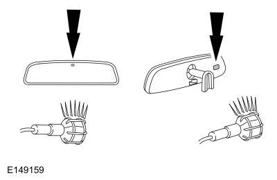
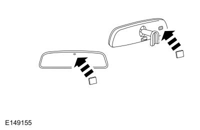
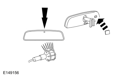
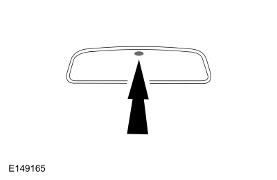
S2 INSPECT THE MIRROR FOR PROPER INSTALLATION
  • Inspect the interior auto-dimming mirror to make sure the rearward facing sensor is at the top of the mirror glass.

Is the rearward facing sensor at the top of the interior auto-dimming mirror glass?
Yes GO to S3
No INSTALL the interior auto-dimming mirror with the rearward facing sensor at the top of the mirror glass. REFER to: Interior Rear View Mirror (501-09 Rear View Mirrors, Removal and Installation).

S3 VERIFY THE FORWARD AND REARWARD FACING SENSORS ARE NOT BLOCKED
  • Visually verify the forward and rearward facing sensors are not blocked or obstructed. Sources of obstruction can include:
    • Stickers, window decals or tags.
    • Fold-down screens for TVs or DVD players.
    • Non-OEM window tinting.
    • Dirt and debris

Are either of the sensors blocked?
Yes If possible, REMOVE the obstruction. If it is not possible to remove the obstruction, ADVISE the customer the blockage will affect the operation of the auto-dimming mirror.
No GO to S4

S4 VERIFY THE OPERATION OF THE INTERIOR AUTO-DIMMING MIRROR - DAYLIGHT CONDITIONS
  • Use a bright lamp to illuminate the forward facing sensor and the rearward facing sensor. The mirror should adjust to a high reflectance state (mirror will be clear).

Did the mirror adjust to a high reflectance (clear) state?
Yes GO to S5
No INSTALL a new interior auto-dimming mirror. REFER to: Interior Rear View Mirror (501-09 Rear View Mirrors, Removal and Installation).

S5 VERIFY THE OPERATION OF THE INTERIOR AUTO-DIMMING MIRROR - NIGHTTIME CONDITIONS
  • NOTE: Covering the sensor(s) with a finger or hand is not adequate for this step. Cover the forward and rearward facing sensors with black electrical tape or other dark material. The mirror should adjust to a high reflectance state (mirror will be clear).

Did the mirror adjust to a high reflectance (clear) state?
Yes GO to S6
No INSTALL a new interior auto-dimming mirror. REFER to: Interior Rear View Mirror (501-09 Rear View Mirrors, Removal and Installation).

S6 VERIFY THE OPERATION OF THE INTERIOR AUTO-DIMMING MIRROR - NIGHTTIME CONDITIONS WITH GLARE
  • NOTE: Covering the sensor(s) with a finger or hand is not adequate for this step. Remove the black electrical tape or other dark material from the rearward facing sensor.
  • Use a bright light to illuminate the rearward facing sensor. The mirror should adjust to a lower reflectance state (mirror will be dark).

Did the mirror adjust to a low reflectance (dark) state?
Yes GO to S7
No GO to S8

S7 VERIFY THE OPERATION OF THE INTERIOR AUTO-DIMMING MIRROR - VEHICLE IN REVERSE AND NIGHTTIME CONDITIONS WITH GLARE
  • NOTE: Covering the sensor(s) with a finger or hand is not adequate for this step. Continue to illuminate the rearward facing sensor with the forward facing sensor covered.
  • Select REVERSE.

Did the mirror adjust to a high reflectance (clear) state after reverse was selected?
Yes Select PARK. The system is operating correctly at this time. REVIEW the operation of the interior auto-dimming mirror feature with the customer.
No GO to S10

S8 CHECK FOR VOLTAGE TO THE INTERIOR AUTO-DIMMING MIRROR
  • Ignition OFF.
  • Disconnect: Interior auto-dimming mirror C9440 (Vehicle without electronic toll collect).
  • Disconnect: Interior auto-dimming mirror C9048 (Vehicle with electronic toll collect).
  • Ignition ON.
  • Measure:
    Click to display connectors

      Vehicle without electronic toll collect


    Positive Lead Measurement / Action Negative Lead
      C9440-9   Ground

    Click to display connectors

      Vehicle with electronic toll collect


    Positive Lead Measurement / Action Negative Lead
      C9048-2   Ground

Is the voltage greater than 11 volts?
Yes GO to S9
No VERIFY that BCM fuse 37 (20A) is OK. If the fuse is OK, REPAIR the circuit. If the fuse is not OK, REFER to the Wiring Diagrams manual to identify the possible causes of the circuit short.

S9 CHECK FOR GROUND AT THE INTERIOR AUTO-DIMMING MIRROR
  • Ignition OFF.
  • Measure:
    Click to display connectors

      Vehicle without electronic toll collect


    Positive Lead Measurement / Action Negative Lead
      C9440-16   Ground

    Click to display connectors

      Vehicle with electronic toll collect


    Positive Lead Measurement / Action Negative Lead
      C9048-22   Ground

Is the resistance less than 3 ohms?
Yes GO to S9
No REPAIR the circuit.

S10 CHECK THE REVERSE INHIBIT CIRCUIT FOR VOLTAGE AT THE INTERIOR AUTO-DIMMING MIRROR WITH THE VEHICLE IN REVERSE
  • Ignition ON.
  • Select REVERSE.
  • Measure:
    Click to display connectors

      Vehicle without electronic toll collect


    Positive Lead Measurement / Action Negative Lead
      C9440-4   Ground

    Click to display connectors

      Vehicle with electronic toll collect


    Positive Lead Measurement / Action Negative Lead
      C9048-7   Ground

Is the voltage greater than 11 volts?
Yes INSTALL a new interior auto-dimming mirror. REFER to: Interior Rear View Mirror (501-09 Rear View Mirrors, Removal and Installation).
No REPAIR the circuit.


    Rear View Mirrors - System Operation and Component Description. Description and Operation

    S..

    Power Mirrors Synchronization. General Procedures

    Synchronization NOTE: The power folding mirrors may need to be synchronized any time the mirrors are folded or unfolded without using the folding switch, or if a new power folding mirror is installed...

    Other information:

    Lincoln Navigator 2018-2025 Workshop Manual: Catalytic Converter RH. Removal and Installation


    Special Tool(s) / General Equipment 303-476 (T94P-9472-A) Socket, Exhaust Gas Oxygen SensorTKIT-1994-LM/MTKIT-1994-FTKIT-1994-FLM/FM Materials Name Specification Motorcraft® High Temperature Nickel Anti-Seize LubricantXL-2 -  Motorcraft® Penetrating and Lock LubricantXL-1 -  Removal NOTE: If the catalytic converter..

    Lincoln Navigator 2018-2025 Workshop Manual: Engine - Overview. Description and Operation


    Overview The 3.5L Ecoboost is a turbocharged engine which may also be described with these terms: GTDI - Gasoline Turbocharged Direct Injection DI - Direct Injection GT - Gasoline Turbocharged Ti-VCT TC - Twin independent Variable Camshaft Timing Turbocharged V6 - 6 cylinder engine 24V - 4 valves per cylinder 4V - 4 valves per cylinde..

    Categories

    • Manuals Home
    • 4th Gen Lincoln Navigator Service Manual (2018 - 2025)
    • Satellite Radio Antenna. Removal and Installation
    • Body Control Module (BCM). Removal and Installation
    • Windshield Washer Pump. Removal and Installation
    • Power Running Board (PRB). Diagnosis and Testing
    • SYNC Module [APIM]. Removal and Installation

    Wheel to Hub Runout Minimization. General Procedures

    Check

    NOTE: Wheel-to-hub optimization is important. Clearance between the wheel and hub can be used to offset or neutralize the Road Force® or run-out of the wheel and tire assembly. For every 0.001 inch of wheel-to-hub clearance, the Road Force® can be affected between 1 and 3 pounds depending on the tire stiffness.

    NOTE: The example below illustrates how the clearance between the wheel and the hub can be used to offset the high spot of radial run-out or Road Force®. Following the procedure will make sure of the best optimization.

    Position the wheel and tire assembly on the vehicle so that the high spot location of radial run-out or Road Force® is at the 6 o'clock position and

    read more

    Copyright © 2025 www.linavigator4.com