Lincoln Navigator: Bumpers / Rear Bumper Cover. Disassembly and Assembly
Special Tool(s) / General Equipment
| Electric Drill |
DISASSEMBLY
NOTE: Disassembly steps in this procedure may contain assembly details.
-
Remove the rear bumper cover.
Refer to: Rear Bumper Cover (501-19 Bumpers, Removal and Installation).
-
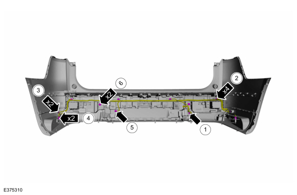
NOTE: The number and location of electrical connectors will vary depending on option content.
-
Disconnect the hands-free liftgate module electrical connector.
-
Disconnect the rear parking aid sensor electrical connectors.
-
Disconnect the rear active park assist sensor electrical connectors.
-
Disconnect the front door keyless entry antenna electrical connectors.
-
Disconnect the bluetooth rear exterior antenna electrical connector.
-
Disconnect the rear fog lamp electrical connectors.
-
Disconnect the hands-free liftgate module electrical connector.
 |
-
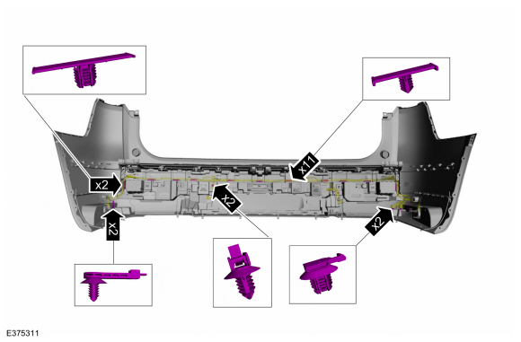
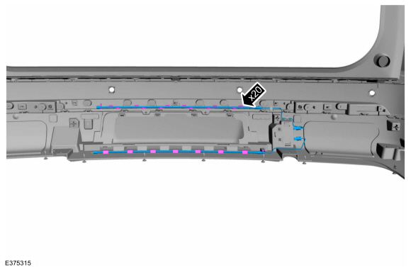
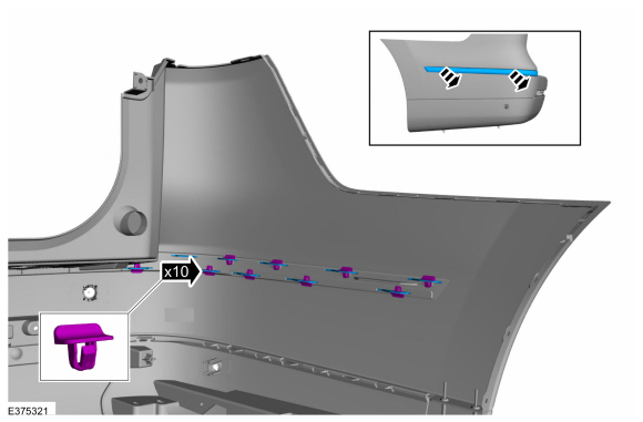
NOTE: The number and location of retainers will vary depending on option content.
Separate the harness retainers and remove the rear bumper cover harness.
 |
Vehicles With: Active Park Assist/Rear Parking Aid
-
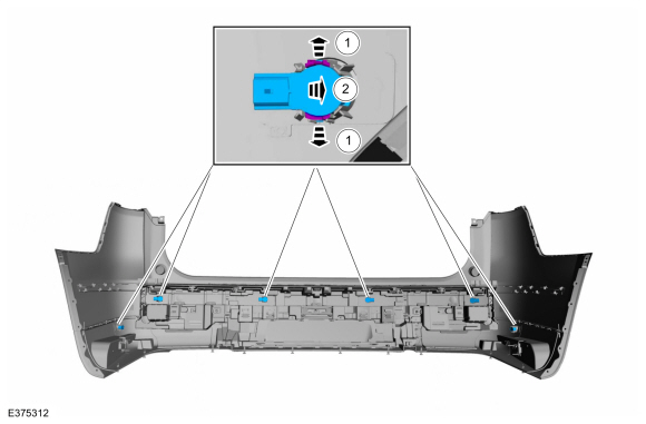
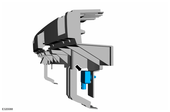
NOTE: Make sure that the isolator rings are installed correctly while installing the sensors.
Remove the rear parking aid and rear active park assist sensors.
-
Release the tabs.
-
Remove the rear parking aid and rear active park assist sensors from the bracket.
-
Release the tabs.
 |
All vehicles
-
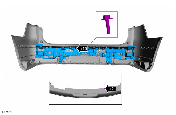
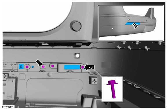
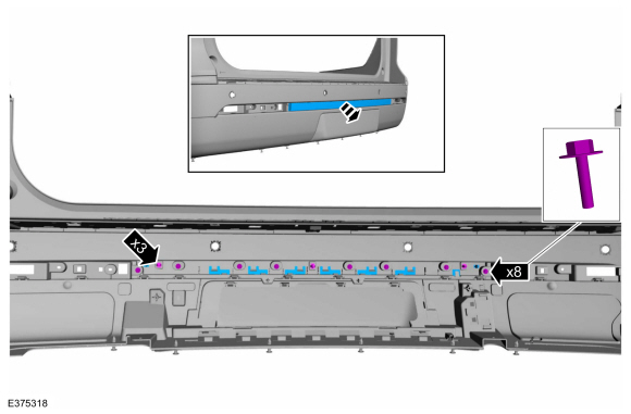
Remove the screws and the rear bumper energy absorber.
 |
-
Remove the bluetooth rear exterior antenna.
 |
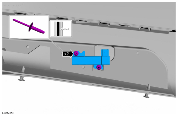
Vehicles With: Hands-Free Liftgate
-
-
Disconnect the electrical connectors.
-
Release the tabs and remove the hands-free liftgate module.
-
Disconnect the electrical connectors.
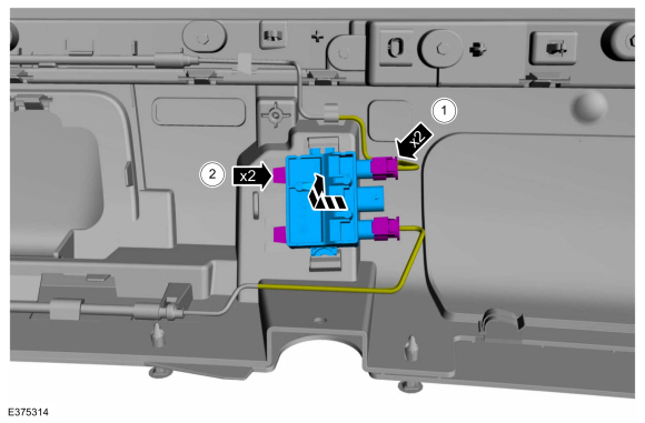 |
-
Release the tabs and remove the hands-free liftgate upper and lower sensors.
 |
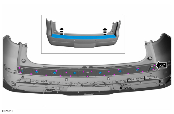
All vehicles
-
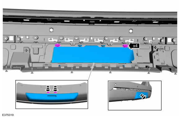
Release the tabs and remove the rear bumper step pad.
 |
-
On both sides.
Remove the screws, release the tabs and remove the rear fog lamp / rear reflector.
 |
-
Remove the screws, release the tabs and remove the rear fog lamp / reversing light / rear reflector.
 |
-
Release the tabs and remove the trailer hitch cover panel.
 |
-
On both sides.
Drill the rivets and remove the front door keyless entry antenna.
Use the General Equipment: Electric Drill
 |
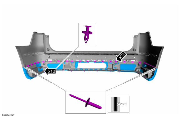
-
On both sides.
Remove the push pins and remove the rear bumper moulding.
Use the General Equipment: Electric Drill
 |
-
Drill the rivets, remove the push pins, release the tabs and remove the rear lower bumper cover panel.
Use the General Equipment: Electric Drill
 |
ASSEMBLY
-
To assemble, reverse the disassembly procedure.
Vehicles With: Rear Parking Aid
-
Check the alignment of the rear parking aid sensors.
Refer to: Azimuth System Check (413-13A Parking Aid, General Procedures).
Refer to: Elevation System Check (413-13A Parking Aid, General Procedures).
-
If any sensor fails the check, diagnose the sensor fault.
Refer to: Parking Aid (413-13A Parking Aid, Diagnosis and Testing).
Vehicles With: Active Park Assist
-
Check the alignment of the rear active park assist sensors.
Refer to: Azimuth System Check (413-13C Parking Aid - Vehicles With: Active Park Assist, General Procedures).
-
If any sensor fails the check, diagnose the sensor fault.
Refer to: Parking Aid (413-13C Parking Aid - Vehicles With: Active Park Assist, Diagnosis and Testing).
 Front Bumper Cover. Disassembly and Assembly
Special Tool(s) /
General Equipment
Electric Drill
DISASSEMBLY
NOTE:
Disassembly steps in this procedure may contain assembly details...

Other information:
Lincoln Navigator 2018-2026 Workshop Manual: Corrosion Prevention. General Procedures
Special Tool(s) / General Equipment Rust Protection Coating Gun Undercoating Gun Materials Name Specification ValuGard™ Premium UndercoatingVG101, VG101A - ValuGard™ Rust InhibitorVG104, VG104A - Motorcraft® Metal Surface Prep WipesZC-31-B - Repair NOTE: Undercoating NOTE: The follo..
Lincoln Navigator 2018-2026 Workshop Manual: Parking Aid. Diagnosis and Testing
Diagnostic Trouble Code (DTC) Chart Diagnostics in this manual assume a certain skill level and knowledge of Ford-specific diagnostic practices. REFER to: Diagnostic Methods (100-00 General Information, Description and Operation). Module DTC Description Action APIM C1001:01 Vision System Camera: General Electrical Failure GO to Pinpoint Test A APIM C1001:..
Categories
- Manuals Home
- 4th Gen Lincoln Navigator Service Manual (2018 - 2026)
- Power Running Board (PRB). Diagnosis and Testing
- Body Control Module (BCM). Removal and Installation
- Remote Function Actuator (RFA) Module. Removal and Installation
- All Terrain Control Module (ATCM). Removal and Installation
- Transmission Fluid Level Check. General Procedures
Rear Stabilizer Bar Link. Removal and Installation
Removal
NOTE: Removal steps in this procedure may contain installation details.
With the vehicle in NEUTRAL, position it on a hoist.Refer to: Jacking and Lifting (100-02 Jacking and Lifting, Description and Operation).
NOTE: Use the hex-holding feature to prevent the stud from turning while removing the nut.
Remove and discard the 2 rear stabilizer bar link nuts and remove the rear stabilizer bar link.Torque: 46 lb.ft (63 Nm)
