Lincoln Navigator: Electronic Engine Controls - 3.5L EcoBoost (272kW/370PS) / Powertrain Control Module (PCM). Removal and Installation
Special Tool(s) / General Equipment
| Ford Diagnostic Equipment |
Removal
-
NOTE: Removal steps in this procedure may contain installation details.
If installing a new PCM , connect a battery charger to the battery to make sure it is charged to maintain proper battery voltage.
Refer to: Battery Charging (414-01 Battery, Mounting and Cables, General Procedures).
-
NOTE: This step is only necessary when installing a new component.
Download the module information to the diagnostic tool using the Programmable Modules Installation routine.
Refer to: Module Configuration - System Operation and Component Description (418-01A Module Configuration, Description and Operation).
Use the General Equipment: Ford Diagnostic Equipment
-
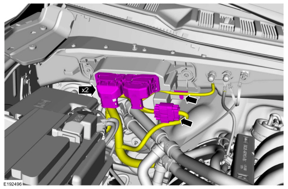
Disconnect the PCM electrical connectors, release the harness retainers to position aside wire harness.
 |
-
-
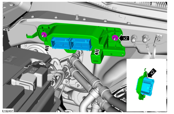
Remove the 2 retainers and the PCM .
Torque: 80 lb.in (9 Nm)
-
Remove the retainers and remove the PCM from the mounting frame.
Torque: 62 lb.in (7 Nm)
-
Remove the 2 retainers and the PCM .
 |
Installation
-
To install, reverse the removal procedure.
-
NOTE: This step is only necessary when installing a new component.
Upload the module information from the diagnostic tool using the Programmable Modules Installation routine.
Refer to: Module Programming (418-01A Module Configuration, General Procedures).
-
NOTE: This step is only necessary when installing a new component.
Carry out the Parameter Reset procedure.
Refer to: Anti-Theft Key Programming - Scan Tool (419-01B Passive Anti-Theft System (PATS), General Procedures).
-
NOTE: This step is only necessary when installing a new component.
Using the scan tool, perform the Misfire Monitor Neutral Profile Correction procedure, following the on-screen instructions.
 Oil Pressure Control Solenoid. Removal and Installation
Removal
NOTE:
Removal steps in this procedure may contain installation details.
Remove the engine front cover.
Refer to: Engine Front Cover (303-01 Engine - 3...
 Turbocharger Boost Pressure (TCBP) and Charger Air Cooler Temperature (CACT) Sensor. Removal and Installation
Removal
NOTE:
Removal steps in this procedure may contain installation details.
NOTE:
Lubricate the O ring with clean engine oil...
Other information:
Lincoln Navigator 2018-2026 Workshop Manual: Specifications
Lubricants, Fluids, Sealers and Adhesives Specifications Motorcraft® DOT 4 LV High Performance Motor Vehicle Brake Fluid / PM-20 WSS-M6C65-A2 Torque Specifications Item Nm lb-ft lb-in Front c..
Lincoln Navigator 2018-2026 Workshop Manual: Roof Reinforcement. Removal and Installation
Special Tool(s) / General Equipment 6.5 mm Drill Bit Self-Piercing Rivet (SPR) Remover/Installer Belt Sander Blind Rivet Gun Locking Pliers Materials Name Specification Metal Bonding AdhesiveTA-1, TA-1-B, 3M™ 08115, LORD Fusor® 108B, Henkel Teroson EP 5055 - Removal NOTE: The following procedure details re..
Categories
- Manuals Home
- 4th Gen Lincoln Navigator Service Manual (2018 - 2026)
- Identification Codes. Description and Operation
- Rear View Mirrors - System Operation and Component Description. Description and Operation
- Liftgate Trim Panel. Removal and Installation
- SYNC Module [APIM]. Removal and Installation
- Neutral Flat Tow Activation and Deactivation. General Procedures
Axle Tube Bearing. Removal and Installation
Special Tool(s) / General Equipment
 205-123
(T78P-1177-A)
205-123
(T78P-1177-A)
Installer, Axle Shaft Oil Seal
 308-047
(T77F-1102-A)
308-047
(T77F-1102-A)
Remover, Bearing Cup Slide Hammer