Lincoln Navigator: Body Repairs - General Information / Joining Techniques. General Procedures
Special Tool(s) / General Equipment
| Spherical Cutter | |
| Plasma Cutter | |
| Air Body Saw | |
| 8 mm Drill Bit | |
| MIG/MAG Welding Equipment |
Materials
| Name | Specification |
|---|---|
| Metal Bonding Adhesive TA-1, TA-1-B, 3M™ 08115, LORD Fusor® 108B, Henkel Teroson EP 5055 |
- |
Repair
NOTE: The following provide general joining options for sectioned or sliced components and are not all inclusive. Regardless of component to be joined, whenever possible a backing plate should be used to assure a quality repair.
NOTE: Rivet Bonding
-
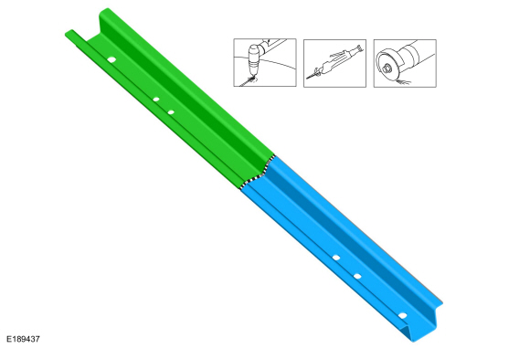
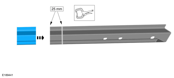
Determine sectioning point of component and make appropriate cut.
Use the General Equipment: Air Body Saw
Use the General Equipment: Spherical Cutter
Use the General Equipment: Plasma Cutter
 |
-
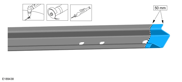
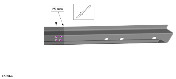
Make a 50 mm wide backing plate from an unused portion of the old or new service part.
Use the General Equipment: Air Body Saw
Use the General Equipment: Spherical Cutter
Use the General Equipment: Plasma Cutter
 |
-
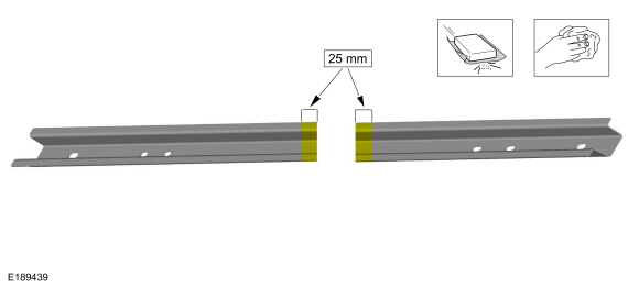
Measure and cut to fit the replacement service component.
-
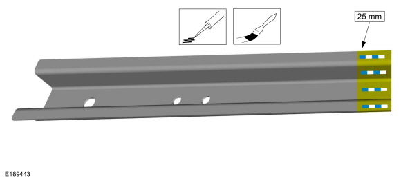
NOTE: 80 to 125 grit sand papers are the recommended for best adhesion.
Remove old adhesive and e-coat from mating surfaces of the original component and the replacement part measuring 25 mm on each.
 |
-
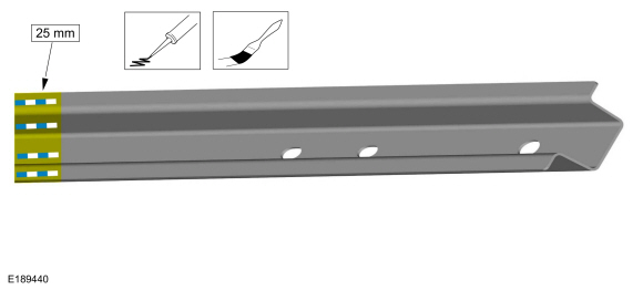
Apply adhesive to existing component and evenly spread using a stiff bristle brush.
Material: Metal Bonding Adhesive / TA-1, TA-1-B, 3M™ 08115, LORD Fusor® 108B, Henkel Teroson EP 5055
 |
-
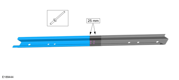
Install and clamp backing plate to existing component.
 |
-
Install appropriate fasteners.
Refer to: Special Repair Considerations for Aluminum Repairs (501-25 Body Repairs - General Information, Description and Operation).
 |
-
Apply adhesive to replacement component and evenly spread using a stiff bristle brush.
Material: Metal Bonding Adhesive / TA-1, TA-1-B, 3M™ 08115, LORD Fusor® 108B, Henkel Teroson EP 5055
 |
-
Install service component and appropriate fasteners.
Refer to: Special Repair Considerations for Aluminum Repairs (501-25 Body Repairs - General Information, Description and Operation).
 |
Repair
NOTE: Welded Method
-
Determine sectioning point of component and make appropriate cut.
Use the General Equipment: Air Body Saw
Use the General Equipment: Spherical Cutter
Use the General Equipment: Plasma Cutter
|
-
After removing the damaged sheet metal panel(s), repair
any damaged flanges on the vehicle using a hammer and dolly.
-
Make a 50 mm wide backing plate from an unused portion of the old or new service part.
Use the General Equipment: Air Body Saw
Use the General Equipment: Spherical Cutter
Use the General Equipment: Plasma Cutter
|
-
Measure and cut to fit the replacement service component.
-
NOTE: 80 to 125 grit sand papers are the recommended for best adhesion.
Remove old adhesive and e-coat from mating surfaces of the original component and the replacement part measuring 25 mm on each.
|
-
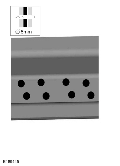
Drill plug weld holes in backer plate as indicated.
Use the General Equipment: 8 mm Drill Bit
 |
-
Install and clamp backing plate to existing component.
|
-
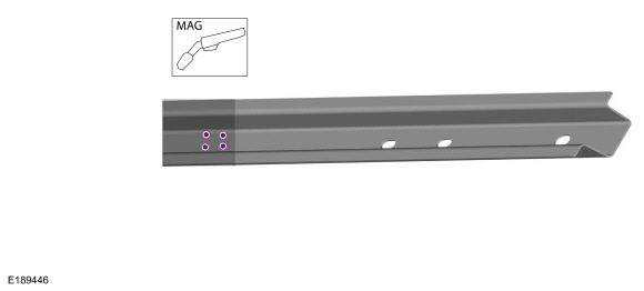
NOTICE: MIG welder must be set up for aluminum application.
Plug weld as indicated.
Use the General Equipment: MIG/MAG Welding Equipment
 |
-
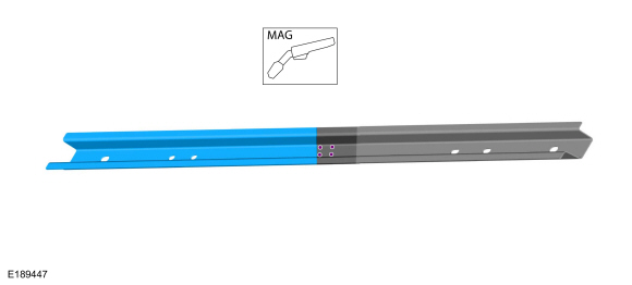
NOTICE: MIG welder must be set up for aluminum application.
Install service component and plug weld as indicated.
Use the General Equipment: MIG/MAG Welding Equipment
 |
-
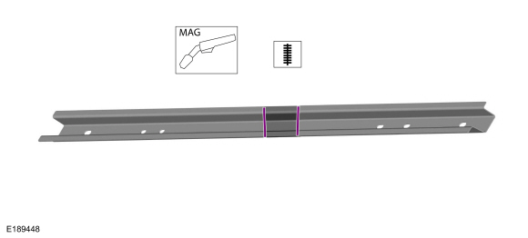
NOTICE: MIG welder must be set up for aluminum application.
Seam weld repair area as indicated.
Use the General Equipment: MIG/MAG Welding Equipment
 |
 Inspection And Repair After Collision Without Supplemental Restraint Deployment. General Procedures
Inspection
If airbags deploy.
Refer to: Inspection and Repair after a Supplemental Restraint System (SRS) Deployment (501-20B)
.
NOTE:
Deployable devices such as airbags, pretensioners and
inflatable belt inflators, may deploy alone or in various combinations
depending on the impact event...
 Plastic Repairs. General Procedures
Materials
Name
Specification
Plastic Bonding AdhesiveTA-9
-
Repair
NOTICE:
Plastic repairs on vehicles equipped with Advanced Driver
Assistance System (ADAS) must not exceed 12 mils (300 microns) of paint
thickness after refinishing...
Other information:
Lincoln Navigator 2018-2026 Workshop Manual: Radiator. Removal and Installation
Removal NOTE: Removal steps in this procedure may contain installation details. Drain the cooling system. Refer to: Engine Cooling System Draining, Vacuum Filling and Bleeding (303-03 Engine Cooling - 3.5L EcoBoost (272kW/370PS), General Procedures)...
Lincoln Navigator 2018-2026 Workshop Manual: Passive Anti-Theft System (PATS) - Overview. Description and Operation
Overview NOTE: This section only describes and diagnosis the Phone as a Key system. In order for the Phone as a Key system to operate, the PATS system must be functioning correctly. For more information about the PATS system Refer to: Passive Anti-Theft System (PATS) - Component Location (419-01C Passive Anti-Theft System (PATS) - Vehicles With: Phone as a Key, Description and O..
Categories
- Manuals Home
- 4th Gen Lincoln Navigator Service Manual (2018 - 2026)
- Telematics Control Unit (TCU) Module. Removal and Installation
- Power Running Board (PRB). Diagnosis and Testing
- All Terrain Control Module (ATCM). Removal and Installation
- Windshield Washer Pump. Removal and Installation
- Transmission Fluid Level Check. General Procedures
Front Stabilizer Bar Link. Removal and Installation
Removal
NOTICE: Suspension fasteners are critical parts that affect the performance of vital components and systems. Failure of these fasteners may result in major service expense. Use the same or equivalent parts if replacement is necessary. Do not use a replacement part of lesser quality or substitute design. Tighten fasteners as specified.
NOTE: Removal steps in this procedure may contain installation details.
With the vehicle in NEUTRAL, position it on a hoist.Refer to: Jacking and Lifting (100-02 Jacking and Lifting, Description and Operation).
NOTICE: Do not use power tools to remove or install the stabilizer bar