• Navigator Manuals
  • Service
  • New
  • Top
  • Sitemap
Lincoln Navigator Manuals

Lincoln Navigator: Instrumentation, Message Center and Warning Chimes / Instrumentation, Message Center and Warning Chimes. Diagnosis and Testing

Lincoln Navigator 2018-2025 Workshop Manual / Instrumentation and Warning Systems / Instrumentation, Message Center and Warning Chimes / Instrumentation, Message Center and Warning Chimes. Diagnosis and Testing

Diagnostic Trouble Code (DTC) Chart

Diagnostics in this manual assume a certain skill level and knowledge of Ford-specific diagnostic practices.
REFER to: Diagnostic Methods (100-00 General Information, Description and Operation).


  Diagnostic Trouble Code Chart


Module   DTC Description Action
  ABS C0049:01 Brake Fluid Level: General Electrical Failure   GO to Pinpoint Test P
  ABS C0049:7B Brake Fluid Level: Low Fluid Level   GO to Pinpoint Test P
  IPC P0460:11 Fuel Level Sensor "A" Circuit: Circuit Short To Ground   GO to Pinpoint Test C
  IPC P0460:13 Fuel Level Sensor "A" Circuit: Circuit Open   GO to Pinpoint Test C
  IPC P1534:01 Restraint Deployment Indicator Circuit: General Electrical Failure   GO to Pinpoint Test BU
  IPC U0100:00 Lost Communication With ECM/PCM "A": No Sub Type Information   GO to Pinpoint Test BV
  IPC U0102:00 Lost Communication with Transfer Case Control Module: No Sub Type Information   GO to Pinpoint Test BV
  IPC U0103:00 Lost Communication With Gear Shift Control Module A: No Sub Type Information   GO to Pinpoint Test BV
  IPC U011D:00 Lost Communication With All Wheel Drive Control Module: No Sub Type Information   GO to Pinpoint Test BV
  IPC U0121:00 Lost Communication With Anti-Lock Brake System (ABS) Control Module "A": No Sub Type Information   GO to Pinpoint Test BV
  IPC U0136:82 Lost Communication With Differential Control Module-Rear: Alive/Sequence Counter Incorrect/Not Updated   GO to Pinpoint Test BV
  IPC U0137:00 Lost Communication With Trailer Brake Control Module: No Sub Type Information   GO to Pinpoint Test BV
  IPC U0140:00 Lost Communication With Body Control Module: No Sub Type Information   GO to Pinpoint Test BV
  IPC U0151:00 Lost Communication With Restraints Control Module: No Sub Type Information   GO to Pinpoint Test BV
  IPC U0158:00 Lost Communication With Head Up Display: No Sub Type Information   GO to Pinpoint Test BV
  IPC U0159:00 Lost Communication With Parking Assist Control Module "A": No Sub Type Information   GO to Pinpoint Test BV
  IPC U0184:00 Lost Communication With Radio: No Sub Type Information   GO to Pinpoint Test BV
  IPC U0193:00 Lost Communication With Digital Audio Control Module "A": No Sub Type Information   GO to Pinpoint Test BV
  IPC U0212:00 Lost Communication With Steering Column Control Module: No Sub Type Information   GO to Pinpoint Test BV
  IPC U0212:82 Lost Communication With Steering Column Control Module: Alive/Sequence Counter Incorrect/Not Updated   GO to Pinpoint Test BV
  IPC U0232:00 Lost Communication With Side Obstacle Detection Control Module "A": No Sub Type Information   GO to Pinpoint Test BV
  IPC U0233:00 Lost Communication With Side Obstacle Detection Control Module "B": No Sub Type Information   GO to Pinpoint Test BV
  IPC U023A:00 Lost Communication With Image Processing Module A: No Sub Type Information   GO to Pinpoint Test BV
  IPC U0253:00 Lost Communication With Accessory Protocol Interface Module: No Sub Type Information   GO to Pinpoint Test BV
  IPC U0401:00 Invalid Data Received from ECM/PCM A: No Sub Type Information   GO to Pinpoint Test BW
  IPC U0401:81 Invalid Data Received from ECM/PCM A: Invalid Serial Data Received   GO to Pinpoint Test BW
  IPC U0401:82 Invalid Data Received from ECM/PCM A: Alive/Sequence Counter Incorrect/Not Updated   GO to Pinpoint Test BW
  IPC U0401:86 Invalid Data Received from ECM/PCM A: Signal Invalid   GO to Pinpoint Test BW
  IPC U0405:56 Invalid Data Received From Cruise Control Module: Invalid/Incompatible Configuration   GO to Pinpoint Test BX
  IPC U0415:00 Invalid Data Received from Anti-Lock Brake System (ABS) Control Module "A": No Sub Type Information   GO to Pinpoint Test BW
  IPC U0415:82 Invalid Data Received from Anti-Lock Brake System (ABS) Control Module "A": Alive/Sequence Counter Incorrect/Not Updated   GO to Pinpoint Test BW
  IPC U0416:82 Invalid Data Received From Vehicle Dynamics Control Module: Alive/Sequence Counter Incorrect/Not Updated   GO to Pinpoint Test BW
  IPC U0420:82 Invalid Data Received from Power Steering Control Module "A": Alive/Sequence Counter Incorrect/Not Updated   GO to Pinpoint Test BW
  IPC U0422:00 Invalid Data Received From Body Control Module: No Sub Type Information   GO to Pinpoint Test BW
  IPC U0431:82 Invalid Data Received From Body Control Module "A": Alive/Sequence Counter Incorrect/Not Updated   GO to Pinpoint Test BW
  IPC U0438:82 Invalid Data Received From Trailer Brake Control Module: Alive/Sequence Counter Incorrect/Not Updated   GO to Pinpoint Test BW
  IPC U0452:81 Invalid Data Received From Restraints Control Module: Invalid Serial Data Received   GO to Pinpoint Test BW
  IPC U0531:82 Invalid Data Received From Rear Gate Module: Alive/Sequence Counter Incorrect/Not Updated   GO to Pinpoint Test BW
  IPC U0533:00 Invalid Data Received From Side Obstacle Detection Control Module "A": No Sub Type Information   GO to Pinpoint Test BW
  IPC U0533:56 Invalid Data Received From Side Obstacle Detection Control Module "A": Invalid/Incompatible Configuration   GO to Pinpoint Test BX
  IPC U0534:00 Invalid Data Received From Side Obstacle Detection Control Module "B": No Sub Type Information   GO to Pinpoint Test BW
  IPC U0534:56 Invalid Data Received From Side Obstacle Detection Control Module "B": Invalid/Incompatible Configuration   GO to Pinpoint Test BX
  IPC U053B:82 Invalid Data Received From Image Processing Module A: Alive/Sequence Counter Incorrect/Not Updated   GO to Pinpoint Test BW
  IPC U0542:82 Invalid Data Received From Headlamp Control Module "A": Alive/Sequence Counter Incorrect/Not Updated   GO to Pinpoint Test BW
  IPC U0545:82 Invalid Data Received From Running Board Control Module "A": Alive/Sequence Counter Incorrect/Not Updated   GO to Pinpoint Test BW
  IPC U0557:00 Invalid Data Received From Front Controls Interface Module "A": No Sub Type Information   GO to Pinpoint Test BW
  IPC U0557:81 Invalid Data Received From Front Controls Interface Module "A": Invalid Serial Data Received   GO to Pinpoint Test BW
  IPC U0557:82 Invalid Data Received From Front Controls Interface Module "A": Alive/Sequence Counter Incorrect/Not Updated   GO to Pinpoint Test BW
  IPC U2100:00 Initial Configuration Not Complete: No Sub Type Information   GO to Pinpoint Test BY
  IPC U3000:04 Control Module: System Internal Failures   GO to Pinpoint Test BZ
  IPC U3000:46 Control Module: Calibration/Parameter Memory Failure   GO to Pinpoint Test BZ
  IPC U3003:16 Battery Voltage: Circuit Voltage Below Threshold   GO to Pinpoint Test CA
  IPC U3003:17 Battery Voltage: Circuit Voltage Above Threshold   GO to Pinpoint Test CB
  IPC U300A:64 Ignition Switch: Signal Plausibility Failure   GO to Pinpoint Test CC
  PCM P0071:00 Ambient Air Temperature Sensor Circuit A Range/Performance: No Sub Type Information   GO to Pinpoint Test AV
  PCM P0072:00 Ambient Air Temperature Sensor Circuit A Low: No Sub Type Information   GO to Pinpoint Test AV
  PCM P0073:00 Ambient Air Temperature Sensor Circuit A High: No Sub Type Information   GO to Pinpoint Test AV
  PCM P0074:00 Ambient Air Temperature Sensor Circuit A Intermittent/Erratic: No Sub Type Information   GO to Pinpoint Test AV
  PCM P0461:00 Fuel Level Sensor "A" Circuit Range/Performance: No Sub Type Information   GO to Pinpoint Test C
  PCM P0462:00 Fuel Level Sensor "A" Circuit Low: No Sub Type Information   GO to Pinpoint Test C
  PCM P0463:00 Fuel Level Sensor "A" Circuit High: No Sub Type Information   GO to Pinpoint Test C
  PCM P0521:00 Engine Oil Pressure Sensor/Switch "A" Circuit Range/Performance: No Sub Type Information   GO to Pinpoint Test AF
  PCM P0522:00 Engine Oil Pressure Sensor/Switch "A" Circuit Low: No Sub Type Information   GO to Pinpoint Test AF
  PCM P0523:00 Engine Oil Pressure Sensor/Switch "A" Circuit High: No Sub Type Information   GO to Pinpoint Test AF
  PCM P0524:00 Engine Oil Pressure Too Low: No Sub Type Information   GO to Pinpoint Test AF
  PCM P25B0:00 Fuel Level Sensor "A" Stuck: No Sub Type Information   GO to Pinpoint Test C
  SCCM B1380:11 Steering Wheel Right Switch Pack: Circuit Short To Ground   GO to Pinpoint Test AR
  SCCM B1380:13 Steering Wheel Right Switch Pack: Circuit Open   GO to Pinpoint Test AR
  SCCM B1380:4A Steering Wheel Right Switch Pack: Incorrect Component Installed   GO to Pinpoint Test AR
  SCCM B1380:96 Steering Wheel Right Switch Pack: Component Internal Failure   GO to Pinpoint Test AR
  SCCM B1380:9E Steering Wheel Right Switch Pack: Stuck On   GO to Pinpoint Test AR

Symptom Chart(s)

Symptom Chart: Instrument Panel Cluster (IPC)

Diagnostics in this manual assume a certain skill level and knowledge of Ford-specific diagnostic practices.
REFER to: Diagnostic Methods (100-00 General Information, Description and Operation).


  Symptom Chart


Condition Possible Sources Actions
A module does not respond to the diagnostic scan tool Refer to the Pinpoint Test  
REFER to: Controller Area Network (CAN) Module Communications Network (418-00A Controller Area Network (CAN) Module Communications Network, Diagnosis and Testing).
The IPC is inoperative Refer to the Pinpoint Test   GO to Pinpoint Test A
Multiple gauges, indicators, RTT indicators, warnings and chimes are inoperative or always on Refer to the Pinpoint Test   GO to Pinpoint Test A

Symptom Chart: Instrument Panel Cluster (IPC) - Gauges

Diagnostics in this manual assume a certain skill level and knowledge of Ford-specific diagnostic practices.
REFER to: Diagnostic Methods (100-00 General Information, Description and Operation).


  Symptom Chart


Condition Possible Sources Actions
Incorrect fuel gauge indication Refer to the Pinpoint Test   GO to Pinpoint Test C
Incorrect speedometer indication Refer to the Pinpoint Test   GO to Pinpoint Test D
Incorrect tachometer indication Refer to the Pinpoint Test   GO to Pinpoint Test F
A virtual gauge is inoperative Refer to the Pinpoint Test   GO to Pinpoint Test B

Symptom Chart: Instrument Panel Cluster (IPC) - RTT Indicators

Diagnostics in this manual assume a certain skill level and knowledge of Ford-specific diagnostic practices.
REFER to: Diagnostic Methods (100-00 General Information, Description and Operation).


  Symptom Chart


Condition Possible Sources Actions
The ABS RTT indicator is never or always displayed Refer to the Pinpoint Test   GO to Pinpoint Test H
The airbag warning RTT indicator is never or always displayed Refer to the Pinpoint Test   GO to Pinpoint Test I
The auto high beam/adaptive high beam RTT indicator is never or always displayed Refer to the Pinpoint Test   GO to Pinpoint Test J
The auto hold RTT indicator is never or always displayed Refer to the Pinpoint Test   GO to Pinpoint Test K
The auto stop-start RTT indicator is never or always displayed Refer to the Pinpoint Test   GO to Pinpoint Test L
The auto tow haul RTT indicator is never or always on Refer to the Pinpoint Test   GO to Pinpoint Test M
The Blind Spot Information System (BLIS®) off RTT indicator is never or always displayed Refer to the Pinpoint Test   GO to Pinpoint Test N
The brake system RTT indicator is never displayed Refer to the Pinpoint Test   GO to Pinpoint Test O
The brake system RTT indicator is always displayed Refer to the Pinpoint Test   GO to Pinpoint Test P
The charging system RTT warning indicator is never or always displayed Refer to the Pinpoint Test   GO to Pinpoint Test Q
The cruise control RTT indicator is never displayed Refer to the Pinpoint Test   GO to Pinpoint Test R
The distance indication RTT indicator is never or always displayed Refer to the Pinpoint Test   GO to Pinpoint Test AB
The door ajar RTT warning indicator is never or always displayed Refer to the Pinpoint Test   GO to Pinpoint Test S
The ELD (eLocker) RTT indicator is never or always displayed Refer to the Pinpoint Test   GO to Pinpoint Test U
The electric park brake RTT warning indicator is never or always displayed Refer to the Pinpoint Test   GO to Pinpoint Test V
The engine over-temperature RTT warning indicator is never or always displayed Refer to the Pinpoint Test   GO to Pinpoint Test W
The forward collision RTT warning indicator is never or always displayed Refer to the Pinpoint Test   GO to Pinpoint Test X
The front fog lamp RTT indicator is never or always displayed Refer to the Pinpoint Test   GO to Pinpoint Test AC
Four-wheel drive RTT indicator is never or always displayed Refer to the Pinpoint Test   GO to Pinpoint Test Y
The high beam RTT indicator is never or always displayed Refer to the Pinpoint Test   GO to Pinpoint Test AC
The hill descent control RTT indicator is never or always displayed Refer to the Pinpoint Test   GO to Pinpoint Test Z
The lane centering aid RTT indicator is never or always displayed Refer to the Pinpoint Test   GO to Pinpoint Test AA
The lane keeping system RTT indicator is never or always displayed Refer to the Pinpoint Test   GO to Pinpoint Test AB
The LH / RH turn RTT indicator is never or always displayed Refer to the Pinpoint Test   GO to Pinpoint Test AC
The LED low beam malfunction RTT indicator is never or always displayed Refer to the Pinpoint Test   GO to Pinpoint Test AD
The lights on RTT indicator is never or always displayed Refer to the Pinpoint Test   GO to Pinpoint Test AE
The low engine oil pressure RTT warning indicator is never or always displayed Refer to the Pinpoint Test   GO to Pinpoint Test AF
The low fuel RTT warning indicator is never or always displayed Refer to the Pinpoint Test   GO to Pinpoint Test AG
The low washer fluid level RTT warning indicator is never or always displayed Refer to the Pinpoint Test   GO to Pinpoint Test AH
The MIL (check engine) RTT warning indicator is never or always displayed Refer to the Pinpoint Test   GO to Pinpoint Test AI
The overspeed warning RTT warning indicator is never or always displayed (Gulf Cooperative Countries [GCC] only) Refer to the Pinpoint Test   GO to Pinpoint Test AJ
The powertrain malfunction (wrench) RTT indicator is never or always displayed Refer to the Pinpoint Test   GO to Pinpoint Test AK
The PRND RTT indicator is never displayed or never displays P Refer to the Pinpoint Test   GO to Pinpoint Test AL
The progressive range select RTT indicator is never displayed Refer to the Pinpoint Test   GO to Pinpoint Test AL
The rear fog lamp RTT indicator is never or always displayed Refer to the Pinpoint Test   GO to Pinpoint Test AC
The seatbelt RTT warning indicator is never or always displayed Refer to the Pinpoint Test   GO to Pinpoint Test AN
The speed sign recognition RTT indicator is never displayed Refer to the Pinpoint Test   GO to Pinpoint Test AW
The stability-traction control RTT indicator (sliding car icon) is never or always displayed Refer to the Pinpoint Test   GO to Pinpoint Test AO
The traction control disabled RTT indicator (sliding car OFF icon) is never or always displayed Refer to the Pinpoint Test   GO to Pinpoint Test AP
The TPMS RTT indicator is never or always displayed Refer to the Pinpoint Test   GO to Pinpoint Test AQ

Symptom Chart: Information And Message Center -Displays

Diagnostics in this manual assume a certain skill level and knowledge of Ford-specific diagnostic practices.
REFER to: Diagnostic Methods (100-00 General Information, Description and Operation).


  Symptom Chart


Condition Possible Sources Actions
The message center is not operating correctly Refer to the Pinpoint Test   GO to Pinpoint Test AR
The message center display is blank Refer to the Pinpoint Test   GO to Pinpoint Test A
A virtual display is inoperative Refer to the Pinpoint Test   GO to Pinpoint Test B
The adaptive cruise control distance display is inoperative Refer to the Pinpoint Test   GO to Pinpoint Test R
The compass is inoperative Refer to the Pinpoint Test  
REFER to: Information and Entertainment System (415-00 Information and Entertainment System - General Information - Vehicles With: SYNC 4, Diagnosis and Testing).
The digital speedometer displays the incorrect speed Refer to the Pinpoint Test   GO to Pinpoint Test D
The DTE -Average Fuel Economy (AFE) display is inoperative Refer to the Pinpoint Test   GO to Pinpoint Test AT
The DTE display is incorrect or fluctuates Refer to the Pinpoint Test   GO to Pinpoint Test AS
The drive mode display (Normal, Normal 4x4 Auto, Excite, Conserve, Slippery, Deep Conditions, Deep Sand, Slow Climb) is incorrect or inoperative Refer to the Pinpoint Test   GO to Pinpoint Test T
The engine oil life display is inoperative or incorrect Refer to the Pinpoint Test   GO to Pinpoint Test BC
The forward collision warning alert display is inoperative Refer to the Pinpoint Test   GO to Pinpoint Test X
The lane centering aid display is inoperative Refer to the Pinpoint Test   GO to Pinpoint Test AA
The lane keeping system display is inoperative Lane keeping alert system concern  
REFER to: Lane Keeping System (419-07 Lane Keeping System, Diagnosis and Testing).
The navigation display is inoperative Refer to the Pinpoint Test  
REFER to: Information and Entertainment System (415-00 Information and Entertainment System - General Information - Vehicles With: SYNC 4, Diagnosis and Testing).
The odometer display is inoperative Refer to the Pinpoint Test   GO to Pinpoint Test E
The off road display is inoperative Refer to the Pinpoint Test   GO to Pinpoint Test AU
The outside air temperature display is inoperative or incorrect Refer to the Pinpoint Test   GO to Pinpoint Test AV
The rear seatbelt monitor display is inoperative Refer to the Pinpoint Test   GO to Pinpoint Test AM
The TPMS display is inoperative or incorrect Refer to the Pinpoint Test   GO to Pinpoint Test AX
The trailer lighting display is inoperative Refer to the Pinpoint Test   GO to Pinpoint Test AZ
The trailer information display is inoperative Refer to the Pinpoint Test   GO to Pinpoint Test AY
The Trip 1/Trip 2 display is incorrect or inoperative   IPC  
REFER to: Instrument Panel Cluster (IPC) (413-01 Instrumentation, Message Center and Warning Chimes, Removal and Installation).

Symptom Chart: Information And Message Center - Warnings

Diagnostics in this manual assume a certain skill level and knowledge of Ford-specific diagnostic practices.
REFER to: Diagnostic Methods (100-00 General Information, Description and Operation).


  Symptom Chart


Condition Possible Sources Actions
A BLIS / CTA warning message is always displayed Refer to the Pinpoint Test   GO to Pinpoint Test N
A brake warning (brake fluid level low, parking brake applied or brake system malfunction) message is never displayed Refer to the Pinpoint Test   GO to Pinpoint Test O
A brake warning (brake fluid level low, parking brake applied or brake system malfunction) message is always displayed Refer to the Pinpoint Test   GO to Pinpoint Test P
The check fuel fill inlet message is always displayed Refer to the Pinpoint Test   GO to Pinpoint Test BA
A door, hood or liftgate ajar warning message is never or always displayed Refer to the Pinpoint Test   GO to Pinpoint Test S
The electric park brake fault message is always displayed Refer to the Pinpoint Test   GO to Pinpoint Test V
An ELD (eLocker) message is never or always displayed Refer to the Pinpoint Test   GO to Pinpoint Test U
The engine oil change message is always displayed Refer to the Pinpoint Test   GO to Pinpoint Test BB
The engine oil life message is never displayed Refer to the Pinpoint Test   GO to Pinpoint Test BC
The ignition-engine on warning message is never or always displayed Refer to the Pinpoint Test   GO to Pinpoint Test BM
A load shed warning message is always displayed Refer to the Pinpoint Test   GO to Pinpoint Test Q
The low fuel warning message is always displayed Refer to the Pinpoint Test   GO to Pinpoint Test AG
The rear seatbelt monitor warning message is never or always displayed Refer to the Pinpoint Test   GO to Pinpoint Test AM
The seatbelt buckle message is never or always displayed Refer to the Pinpoint Test   GO to Pinpoint Test AN
Service AdvanceTrac® warning message is always displayed Refer to the Pinpoint Test   GO to Pinpoint Test H
The shift to park message is always displayed Refer to the Pinpoint Test   GO to Pinpoint Test AL
A TPMS malfunction message is always displayed Refer to the Pinpoint Test   GO to Pinpoint Test AQ
The tire training complete message is never on (sensor training incomplete) Refer to the Pinpoint Test   GO to Pinpoint Test BD
A tire training message (train left front, right front, left rear or right rear tire) message is never displayed Refer to the Pinpoint Test   GO to Pinpoint Test BD
The tires not trained message is always displayed Refer to the Pinpoint Test   GO to Pinpoint Test BD

Symptom Chart: Warning Chimes

Diagnostics in this manual assume a certain skill level and knowledge of Ford-specific diagnostic practices.
REFER to: Diagnostic Methods (100-00 General Information, Description and Operation).


  Symptom Chart


Condition Possible Sources Actions
All the chimes are inoperative Refer to the Pinpoint Test   GO to Pinpoint Test A
The chime always sounds Refer to the Pinpoint Test   GO to Pinpoint Test BE
The chime only sounds from the IPC Refer to the Pinpoint Test   GO to Pinpoint Test BF
The active park assist/parking aid warning chime is inoperative Refer to the Pinpoint Test   GO to Pinpoint Test BG
The adaptive cruise control warning chime is inoperative Refer to the Pinpoint Test   GO to Pinpoint Test BG
The airbag secondary warning chime is inoperative Refer to the Pinpoint Test   GO to Pinpoint Test BH
The airbag secondary warning chime has activated   IPC  
REFER to: Instrument Panel Cluster (IPC) (413-01 Instrumentation, Message Center and Warning Chimes, Removal and Installation).
The backup warning chime is inoperative Refer to the Pinpoint Test   GO to Pinpoint Test BI
The Belt-Minder® feature is inoperative Refer to the Pinpoint Test   GO to Pinpoint Test BJ
The Belt-Minder® cannot be deactivated MyKey® programmed key in use The system is operating correctly. Use an administrator key to disable the Belt-Minder®.
The CTA warning chime is inoperative Refer to the Pinpoint Test   GO to Pinpoint Test BG
The door ajar warning chime is inoperative Refer to the Pinpoint Test   GO to Pinpoint Test BK
The forward collision warning chime is inoperative Refer to the Pinpoint Test   GO to Pinpoint Test BG
The headlamps on warning chime is inoperative Refer to the Pinpoint Test   GO to Pinpoint Test BL
The highway assist (hard takeover) warning chime is inoperative Refer to the Pinpoint Test   GO to Pinpoint Test BG
The ignition-engine on warning chime is inoperative Refer to the Pinpoint Test   GO to Pinpoint Test BM
The memory feedback chime is inoperative Refer to the Pinpoint Test   GO to Pinpoint Test BN
The message center warning chime is inoperative Refer to the Pinpoint Test   GO to Pinpoint Test BO
The perimeter alarm chime is inoperative Refer to the Pinpoint Test   GO to Pinpoint Test BP
The power liftgate warning chime is inoperative Refer to the Pinpoint Test   GO to Pinpoint Test BQ
The seatbelt warning chime is inoperative Refer to the Pinpoint Test   GO to Pinpoint Test BJ
The Service AdvanceTrac® warning chime is inoperative Refer to the Pinpoint Test   GO to Pinpoint Test BS
The transmission not in park warning chime is inoperative Refer to the Pinpoint Test   GO to Pinpoint Test BR
The turn signal-hazard on warning chime is inoperative Refer to the Pinpoint Test   GO to Pinpoint Test BT
The turn signal left on chime is inoperative Refer to the Pinpoint Test   GO to Pinpoint Test BT

Pinpoint Tests


PINPOINT TEST A: THE IPC (INSTRUMENT PANEL CLUSTER) IS INOPERATIVE/MULTIPLE GAUGES, RTT (RECONFIGURABLE TELLTALE) INDICATORS, WARNINGS AND CHIMES ARE INOPERATIVE OR ALWAYS ON

Normal Operation and Fault Conditions

The IPC receives hot at all times voltage from the BCM . The IPC receives the ignition status message for the RUN/START or ACC input from the BCM through the GWM over the CAN .

Possible Sources

  • Fuse
  • Communication concern
  • Scheduled module software update failure (over-the-air update)
  • GWM
  • IPC

Visual Inspection and Pre-checks

  • Inspect the BCM fuse 13 (7.5A).
A1 VERIFY AN OVER-THE-AIR IPC (INSTRUMENT PANEL CLUSTER) SOFTWARE UPDATE WAS PERFORMED
  • Connect the diagnostic scan tool to the vehicle.
  • Ignition ON.
  • View the Connected Vehicle dashboard in PTS .
  • Review the update calendar and verify if any IPC software updates were performed.

Were any over-the-air software updates performed and failed?
Yes Using the diagnostic scan tool, PEFORM the appropriate scheduled software update for the IPC . For additional information, REFER to Section 418-01B.
No GO to A2

A2 PERFORM THE NETWORK TEST FOR ALL MODULES
  • Using a diagnostic scan tool, perform a network test.

Do all modules pass the network test?
Yes GO to A3
No
REFER to: Controller Area Network (CAN) Module Communications Network (418-00A Controller Area Network (CAN) Module Communications Network, Diagnosis and Testing).

A3 CHECK THE GWM (GATEWAY MODULE A) DIAGNOSTIC TROUBLE CODES (DTCS)
  • Using a diagnostic scan tool, check the GWM Continuous Memory Diagnostic Trouble Codes (DTCs).

Are any Diagnostic Trouble Codes (DTCs) recorded?
Yes
REFER to: Controller Area Network (CAN) Module Communications Network (418-00A Controller Area Network (CAN) Module Communications Network, Diagnosis and Testing).
No GO to A4

A4 PERFORM THE IPC (INSTRUMENT PANEL CLUSTER) SELF-TEST
  • Using a diagnostic scan tool, perform the IPC self-test.
  • Check for recorded Diagnostic Trouble Codes (DTCs) from the IPC self-test.

Are any Diagnostic Trouble Codes (DTCs) recorded?
Yes REFER to the DTC Chart in this section.
No GO to A5

A5 CHECK FOR CORRECT IPC (INSTRUMENT PANEL CLUSTER) OPERATION
  • Ignition OFF.
  • Disconnect and inspect the IPC connector.
  • Repair:
    • corrosion (install new connector or terminals – clean module pins)
    • damaged or bent pins – install new terminals/pins
    • pushed-out pins – install new pins as necessary
  • Reconnect the IPC connector. Make sure it seats and latches correctly.
  • Operate the system and determine if the concern is still present.

Is the concern still present?
Yes CHECK OASIS for any applicable service articles: TSB , GSB , SSM or FSA . If a service article exists for this concern, DISCONTINUE this test and FOLLOW the service article instructions. If no service articles address this concern, INSTALL a new IPC .
REFER to: Instrument Panel Cluster (IPC) (413-01 Instrumentation, Message Center and Warning Chimes, Removal and Installation).
No The system is operating correctly at this time. The concern may have been caused by module connections. ADDRESS the root cause of any connector or pin issues.

PINPOINT TEST B: A VIRTUAL GAUGE IS INOPERATIVE

Normal Operation and Fault Conditions

See Virtual Gauges. REFER to: Instrument Panel Cluster (IPC) - System Operation and Component Description (413-01 Instrumentation, Message Center and Warning Chimes, Description and Operation).

Engine Temperature Gauge

    Engine Temperature Gauge

  • If the engine coolant temperature data or engine overheat indication request messages are missing for less than 5 seconds, the IPC defaults the temperature gauge to the last indication state, based upon the last message received.
  • If the engine coolant temperature data or engine overheat indication request messages are missing for 5 seconds or longer, the IPC defaults the temperature gauge to the full hot position.

Fuel Gauge

    Fuel Gauge

  • If the IPC does not receive the fuel level input for less than 33 seconds, the IPC defaults the fuel gauge to the last indication state based on the last input received.
  • If the IPC does not receive the fuel level input for longer than 33 seconds, the IPC defaults the fuel gauge to empty (E).

Speedometer

    Speedometer

  • If the vehicle speed message is missing or invalid for less than 5 seconds, the IPC defaults the speedometer to the last indication state, based upon the last message received.
  • If the vehicle speed message is missing or invalid for 5 seconds or longer, the IPC defaults the speedometer to 0 km/h (0 mph).

Tachometer

    Tachometer

  • If the engine rpm message is missing for less than 5 seconds, the IPC defaults the tachometer to the last indication state, based upon the last message received.
  • If the engine rpm message is missing for 5 seconds or longer, the IPC defaults the tachometer to 0 rpm.

Possible Sources

  • Communication concern
  • GWM
  • PCM
  • IPC
B1 VERIFY THE IPC (INSTRUMENT PANEL CLUSTER) IS SET TO DISPLAY THE GAUGE
  • Ignition ON.
  • NOTE: The IPC and message center navigation can be found in the Owner's Literature. Using the message center controls, make sure the IPC is set to display the gauge in question.

Is the IPC set to display the gauge?
Yes GO to B2
No The virtual gauge is operating correctly. The IPC was not set to display the gauge in question.

B2 PERFORM THE IPC (INSTRUMENT PANEL CLUSTER) SELF-TEST
  • Using a diagnostic scan tool, perform the IPC self-test.
  • Check for recorded Diagnostic Trouble Codes (DTCs).

Are any Diagnostic Trouble Codes (DTCs) recorded?
Yes REFER to the DTC Chart in this section.
No GO to B3

B3 PERFORM THE PCM (POWERTRAIN CONTROL MODULE) SELF-TEST
  • Using a diagnostic scan tool, perform the PCM self-test.
  • Check for recorded Diagnostic Trouble Codes (DTCs).

Are any Diagnostic Trouble Codes (DTCs) recorded?
Yes
REFER to: Electronic Engine Controls (303-14 Electronic Engine Controls - 3.5L EcoBoost (272kW/370PS), Diagnosis and Testing).
No GO to B4

B4 CHECK THE GWM (GATEWAY MODULE A) DIAGNOSTIC TROUBLE CODES (DTCS)
  • Using a diagnostic scan tool, check the GWM Continuous Memory Diagnostic Trouble Codes (DTCs).

Are any Diagnostic Trouble Codes (DTCs) recorded?
Yes
REFER to: Controller Area Network (CAN) Module Communications Network (418-00A Controller Area Network (CAN) Module Communications Network, Diagnosis and Testing).
No GO to B5

B5 CHECK FOR CORRECT IPC (INSTRUMENT PANEL CLUSTER) OPERATION
  • Ignition OFF.
  • Disconnect and inspect the IPC connector.
  • Repair:
    • corrosion (install new connector or terminals – clean module pins)
    • damaged or bent pins – install new terminals/pins
    • pushed-out pins – install new pins as necessary
  • Reconnect the IPC connector. Make sure it seats and latches correctly.
  • Operate the system and determine if the concern is still present.

Is the concern still present?
Yes CHECK OASIS for any applicable service articles: TSB , GSB , SSM or FSA . If a service article exists for this concern, DISCONTINUE this test and FOLLOW the service article instructions. If no service articles address this concern, INSTALL a new IPC .
REFER to: Instrument Panel Cluster (IPC) (413-01 Instrumentation, Message Center and Warning Chimes, Removal and Installation).
No The system is operating correctly at this time. The concern may have been caused by module connections. ADDRESS the root cause of any connector or pin issues.

PINPOINT TEST C: INCORRECT FUEL GAUGE INDICATION

Refer to Wiring Diagrams Cell 60 for schematic and connector information.

Normal Operation and Fault Conditions

See Fuel Gauge. REFER to: Instrument Panel Cluster (IPC) - System Operation and Component Description (413-01 Instrumentation, Message Center and Warning Chimes, Description and Operation).

DTC Fault Trigger Conditions

DTC Description Fault Trigger Condition
IPC P0460:11 Fuel Level Sensor 'A' Circuit: Circuit Short To Ground A continuous and on-demand DTC that sets in the IPC if the fuel level input is pulled low out of range on the fuel level input circuit indicating a short to ground for 33 seconds or longer. The IPC defaults the fuel gauge to empty (E).
IPC P0460:13 Fuel Level Sensor 'A' Circuit: Circuit Open A continuous and on-demand DTC that sets in the IPC if the fuel level input is sent high out of range on the fuel level input circuit indicating an open or short to voltage for 33 seconds or longer. The IPC defaults the fuel gauge to empty (E).
PCM P0461:00 Fuel Level Sensor 'A' Circuit Range/Performance: No Sub Type Information Sets when the PCM determines the fuel level input signal repeatedly moves in and out of range, exceeding the minimum or maximum allowable calibrated parameters for a specified fuel fill percentage in the fuel tank. Follow the pinpoint test using the Diagnostic Trouble Codes (DTCs) set in the IPC .
PCM P0462:00 Fuel Level Sensor 'A' Circuit Low: No Sub Type Information Sets in the PCM when the PCM detects a short to ground on the fuel pump and sender unit signal circuit based on the messaged input received from the IPC . Follow the pinpoint test using the Diagnostic Trouble Codes (DTCs) set in the IPC .
PCM P0463:00 Fuel Level Sensor 'A' Circuit High: No Sub Type Information Sets in the PCM when the PCM detects an open or a short to voltage on the fuel pump and sender unit signal circuit based on the messaged input received from the IPC . Follow the pinpoint test using the Diagnostic Trouble Codes (DTCs) set in the IPC .
PCM P25B0:00 Fuel Level Sensor 'A' Stuck: No Sub Type Information Sets when the PCM determines the value of the fuel level input signal is stuck, that the fuel level input signal does not change or does not correspond with the calculated fuel usage. Follow the pinpoint test using the Diagnostic Trouble Codes (DTCs) set in the IPC .

Possible Sources

  • Wiring, terminals or connectors
  • Fuel pump and sender unit
  • Fuel level sender (float and card)
  • Fuel tank
  • IPC

Visual Inspection and Pre-checks

  • Inspect the fuel tank for signs of damage that can affect the float operation inside the tank.

NOTE: Following any fuel gauge repairs, remove BCM fuse 13 (7.5A) for one minute then reinstall to reset the fuel gauge timers.

C1 CARRY OUT THE IPC (INSTRUMENT PANEL CLUSTER) SELF-TEST
  • Ignition ON.
  • Using a diagnostic scan tool, perform the IPC self-test.
  • Check for recorded Diagnostic Trouble Codes (DTCs) from the IPC self-test.

Are any Diagnostic Trouble Codes (DTCs) recorded?
Yes For DTC P0460:11, GO to C2
For DTC P0460:13, GO to C5
For all other Diagnostic Trouble Codes (DTCs), REFER to the DTC Chart in this section.
No GO to C9

C2 CHECK THE FUEL LEVEL INPUT FOR A SHORT TO GROUND
  • Ignition OFF.
  • Disconnect Fuel Pump And Sender Unit C4330 .
  • Ignition ON.
  • Wait one minute.
  • NOTE: DTC P0460:11 can also be present when carrying out this step and should be disregarded at this time. Using a diagnostic scan tool, repeat the IPC on-demand self-test.

Is DTC P0460:13 present?
Yes GO to C10
No GO to C3

C3 CHECK THE FUEL PUMP AND SENDER UNIT SIGNAL CIRCUIT FOR A SHORT TO GROUND AT THE IPC (INSTRUMENT PANEL CLUSTER)
  • Ignition OFF.
  • Disconnect IPC C220A .
  • Measure:
    Click to display connectors
    Positive Lead Measurement / Action Negative Lead
      C220A-10   Ground

Is the resistance greater than 10,000 ohms?
Yes GO to C4
No REPAIR the circuit.

C4 CHECK THE FUEL PUMP AND SENDER UNIT SIGNAL AND RETURN CIRCUITS FOR A SHORT TOGETHER AT THE IPC (INSTRUMENT PANEL CLUSTER)
  • Measure:
    Click to display connectors
    Positive Lead Measurement / Action Negative Lead
      C220A-10   C220A-2

Is the resistance greater than 10,000 ohms?
Yes GO to C14
No REPAIR the circuits.

C5 CHECK THE FUEL PUMP AND SENDER UNIT FOR AN OPEN
  • Ignition OFF.
  • Disconnect Fuel Pump And Sender Unit C4330 .
  • Connect a fused jumper wire:
    Click to display connectors
    Lead 1 Measurement / Action Lead 2
      C4330-2   C4330-1
  • Ignition ON.
  • Wait one minute.
  • NOTE: DTC P0460:13 can also be present when carrying out this step and should be disregarded at this time. Using a diagnostic scan tool, repeat the IPC self-test.

Is DTC P0460:11 present?
Yes REMOVE the fused jumper wire. GO to C10
No REMOVE the fused jumper wire. GO to C6

C6 CHECK THE FUEL LEVEL SIGNAL CIRCUIT FOR A SHORT TO VOLTAGE AT THE IPC (INSTRUMENT PANEL CLUSTER)
  • Ignition OFF.
  • Disconnect IPC C220A .
  • Ignition ON.
  • Measure:
    Click to display connectors
    Positive Lead Measurement / Action Negative Lead
      C220A-10   Ground

Is any voltage present?
Yes REPAIR the circuit.
No GO to C7

C7 CHECK THE FUEL LEVEL SIGNAL CIRCUIT FOR AN OPEN BETWEEN THE IPC (INSTRUMENT PANEL CLUSTER) AND THE FUEL PUMP AND SENDER UNIT
  • Ignition OFF.
  • Measure:
    Click to display connectors
    Positive Lead Measurement / Action Negative Lead
      C220A-10   C4330-2

Is the resistance less than 3 ohms?
Yes GO to C8
No REPAIR the circuit.

C8 CHECK THE FUEL LEVEL RETURN CIRCUIT FOR AN OPEN BETWEEN THE IPC (INSTRUMENT PANEL CLUSTER) AND THE FUEL PUMP AND SENDER UNIT
  • Measure:
    Click to display connectors
    Positive Lead Measurement / Action Negative Lead
      C220A-2   C4330-1

Is the resistance less than 3 ohms?
Yes GO to C14
No REPAIR the circuit.

C9 INSPECT THE FUEL TANK
  • Visually inspect the fuel tank for any damage or deformation.

Is the fuel tank OK?
Yes GO to C10
No VERIFY the fuel level sensor and fuel pump module are OK. INSTALL a new fuel tank.
REFER to: Fuel Tank (310-01 Fuel Tank and Lines - 3.5L EcoBoost (272kW/370PS), Removal and Installation).

C10 CHECK THE FUEL PUMP AND SENDER UNIT
  • Disconnect and inspect the fuel pump and sender unit connector.
  • Repair:
    • corrosion (install new connector or terminals-clean module pins)
    • damaged pins-install new terminals/pins
    • pushed-out pins-install new pins as necessary
  • Reconnect the fuel pump and sender unit connector. Make sure it seats and latches correctly.
  • Operate the system and determine if the concern is still present.

Is the concern still present?
Yes GO to C11
No The system is operating correctly at this time. The concern may have been caused by component connections. ADDRESS the root cause of any connector or pin issues.

C11 CHECK THE FUEL PUMP MODULE

NOTE: The fuel pump module resistance measures between 10 ohms ± 2 ohms at the upper stop position and 180 ohms ± 4 ohms at the lower stop position.

  • Remove the fuel pump and sender unit.
    REFER to: Fuel Pump and Sender Unit (310-01 Fuel Tank and Lines - 3.5L EcoBoost (272kW/370PS), Removal and Installation).
  • While moving the float arm from the lower stop position to the upper stop position measure:
    Click to display connectors
    Positive Lead Measurement / Action Negative Lead
    Fuel Pump and Sender Unit - Pin 1, component side. Fuel Pump and Sender Unit - Pin 2, component side.

Does the resistance slowly decrease from approximately 180 ± 4 ohms at the lower stop to 10 ± 2 ohms at the upper stop?
Yes GO to C13
No GO to C12

C12 CHECK THE FUEL LEVEL SENDER FOR CORRECT OPERATION
  • Disconnect the fuel level sender (float and card) input wire from the fuel pump and sender unit.
  • Measure the resistance between the fuel level sender (float and card) input wire and the fuel level sender (float and card) ground while slowly moving the float arm between the lower and upper stop position.
    Click to display connectors
    Positive Lead Measurement / Action Negative Lead
    Fuel Level Sender (Component Side) - Pin 1 Fuel Level Sender (Component Side) - Pin 2

Does the resistance slowly decrease from approximately 180 ± 4 ohms at the lower stop to 10 ± 2 ohms at the upper stop?
Yes INSTALL a new fuel pump and sender unit.
REFER to: Fuel Pump and Sender Unit (310-01 Fuel Tank and Lines - 3.5L EcoBoost (272kW/370PS), Removal and Installation).
No INSTALL a new fuel level sender (float and card).
REFER to: Fuel Level Sender (310-01 Fuel Tank and Lines - 3.5L EcoBoost (272kW/370PS), Removal and Installation).

C13 CHECK THE FUEL PUMP AND SENDER UNIT SIGNAL AND RETURN CIRCUITS FOR HIGH RESISTANCE
  • Ignition OFF.
  • Disconnect IPC C220A .
  • Connect a fused jumper wire:
    Click to display connectors
    Lead 1 Measurement / Action Lead 2
      C4330-1   C4330-2
  • Measure:
    Click to display connectors
    Positive Lead Measurement / Action Negative Lead
      C220A-10   C220A-2

Is the resistance less than 3 ohms?
Yes REMOVE the fused jumper wire. GO to C14
No REMOVE the fused jumper wire. REPAIR the circuits for high resistance.

C14 CHECK FOR CORRECT IPC (INSTRUMENT PANEL CLUSTER) OPERATION
  • Ignition OFF.
  • Disconnect and inspect the IPC connector.
  • Repair:
    • corrosion (install new connector or terminals – clean module pins)
    • damaged or bent pins – install new terminals/pins
    • pushed-out pins – install new pins as necessary
  • Reconnect the IPC connector. Make sure it seats and latches correctly.
  • Operate the system and determine if the concern is still present.

Is the concern still present?
Yes CHECK OASIS for any applicable service articles: TSB , GSB , SSM or FSA . If a service article exists for this concern, DISCONTINUE this test and FOLLOW the service article instructions. If no service articles address this concern, INSTALL a new IPC .
REFER to: Instrument Panel Cluster (IPC) (413-01 Instrumentation, Message Center and Warning Chimes, Removal and Installation).
No The system is operating correctly at this time. The concern may have been caused by module connections. ADDRESS the root cause of any connector or pin issues.

PINPOINT TEST D: INCORRECT SPEEDOMETER INDICATION

Normal Operation and Fault Conditions

See Speedometer. REFER to: Instrument Panel Cluster (IPC) - System Operation and Component Description (413-01 Instrumentation, Message Center and Warning Chimes, Description and Operation).

If the vehicle speed message is missing or invalid for less than 5 seconds, the IPC defaults the speedometer to the last indication state, based upon the last message received.

Possible Sources

  • Axle ratio
  • Tire size
  • ABS concern
  • IPC

Visual Inspection and Pre-checks

  • Verify the tire size on the vehicle matches the tire size listed on the vehicle certification label.
D1 CHECK THE AXLE RATIO CONFIGURATION
  • NOTE: The vehicle build axle ratio can be found in PTS under the OASIS tab. Locate and determine the vehicle build axle ratio.

Does the vehicle's axle ratio match the vehicle build axle ratio?
Yes GO to D2
No CONFIGURE the correct axle ratio as required.

D2 CHECK THE TIRE SIZE
  • NOTE: The correct tire size can be found on the VC label. Verify the size of the tires installed on the vehicle matches the VC label.
    REFER to: Identification Codes (100-01 Identification Codes, Description and Operation).

Does the tire size match the VC label?
Yes GO to D3
No INSTALL the correct size tires.

D3 PERFORM THE IPC (INSTRUMENT PANEL CLUSTER) SELF-TEST
  • Using a diagnostic scan tool, perform the IPC self-test.
  • Check for recorded Diagnostic Trouble Codes (DTCs) from the IPC self-test.

Are any Diagnostic Trouble Codes (DTCs) recorded?
Yes REFER to the DTC Chart in this section.
No GO to D4

D4 PERFORM THE ABS (ANTI-LOCK BRAKE SYSTEM) MODULE SELF-TEST
  • Using a diagnostic scan tool, perform the ABS module self-test.

Are any Diagnostic Trouble Codes (DTCs) recorded?
Yes REFER to the Master DTC Chart.
No GO to D5

D5 CHECK THE PCM (POWERTRAIN CONTROL MODULE) VEHICLE SPEED PID (PARAMETER IDENTIFICATION)
  • Using a diagnostic scan tool, view the IPC Parameter Identifications (PIDs).
  • Access the  PCM  and monitor the  VSS (Kph)  PID

  • Drive the vehicle at 32 km/h (20 mph), 64 km/h (40 mph) and 97 km/h (60 mph) while monitoring the PID ..

Does the speedometer indicate between 31-34 km/h (19-21 mph), 63-69 km/h (39-43 mph) and 93-103 km/h (58-64 mph) at the 3 PCM PID values?
Yes GO to D6
No GO to D7

D6 OBSERVE THE SPEEDOMETER OPERATION
  • Observe the speedometer while operating at various speeds and stopping frequently.

Does the speedometer begin at 0 km/h (0 mph) and fully return to the 0 km/h (0 mph) position when the vehicle is stopped?
Yes The speedometer is operating correctly at this time.
No GO to D7

D7 CHECK FOR CORRECT IPC (INSTRUMENT PANEL CLUSTER) OPERATION
  • Ignition OFF.
  • Disconnect and inspect the IPC connector.
  • Repair:
    • corrosion (install new connector or terminals – clean module pins)
    • damaged or bent pins – install new terminals/pins
    • pushed-out pins – install new pins as necessary
  • Reconnect the IPC connector. Make sure it seats and latches correctly.
  • Operate the system and determine if the concern is still present.

Is the concern still present?
Yes CHECK OASIS for any applicable service articles: TSB , GSB , SSM or FSA . If a service article exists for this concern, DISCONTINUE this test and FOLLOW the service article instructions. If no service articles address this concern, INSTALL a new IPC .
REFER to: Instrument Panel Cluster (IPC) (413-01 Instrumentation, Message Center and Warning Chimes, Removal and Installation).
No The system is operating correctly at this time. The concern may have been caused by module connections. ADDRESS the root cause of any connector or pin issues.

PINPOINT TEST E: THE ODOMETER IS INOPERATIVE

Normal Operation and Fault Conditions

See Odometer. REFER to: Message Center - System Operation and Component Description (413-01 Instrumentation, Message Center and Warning Chimes, Description and Operation).

If the odometer count message is missing from the PCM for 5 seconds or longer, the IPC defaults the odometer display to all dashes (------).

If the odometer count message is deemed invalid by the IPC , the IPC defaults the odometer display to all dashes (------). If the NVM becomes corrupted or if any NVM failure occurs, odometer displays ERROR.

Possible Sources

  • Communication concern
  • PCM concern
  • GWM concern
  • IPC
E1 CHECK FOR CORRUPTED NON-VOLATILE MEMORY (NVM)
  • Ignition ON.
  • Observe the message center display area.

Does the odometer display ERROR?
Yes INSTALL a new IPC .
REFER to: Instrument Panel Cluster (IPC) (413-01 Instrumentation, Message Center and Warning Chimes, Removal and Installation).
No GO to E2

E2 PERFORM THE IPC (INSTRUMENT PANEL CLUSTER) SELF-TEST
  • Using a diagnostic scan tool, perform the IPC self-test.

Are any Diagnostic Trouble Codes (DTCs) recorded?
Yes REFER to the DTC Chart in this section.
No GO to E3

E3 PERFORM THE PCM (POWERTRAIN CONTROL MODULE) KOEO (KEY ON, ENGINE OFF) SELF-TEST
  • Using a diagnostic scan tool, perform the PCM KOEO self-test.

Are any Diagnostic Trouble Codes (DTCs) recorded?
Yes REFER to the Master DTC Chart.
No GO to E4

E4 CHECK THE GWM (GATEWAY MODULE A) DIAGNOSTIC TROUBLE CODES (DTCS)
  • Using a diagnostic scan tool, check the GWM Continuous Memory Diagnostic Trouble Codes (CMDTCs).

Are any Diagnostic Trouble Codes (DTCs) recorded?
Yes
REFER to: Controller Area Network (CAN) Module Communications Network (418-00A Controller Area Network (CAN) Module Communications Network, Diagnosis and Testing).
No GO to E5

E5 CHECK FOR CORRECT IPC (INSTRUMENT PANEL CLUSTER) OPERATION
  • Ignition OFF.
  • Disconnect and inspect the IPC connector.
  • Repair:
    • corrosion (install new connector or terminals – clean module pins)
    • damaged or bent pins – install new terminals/pins
    • pushed-out pins – install new pins as necessary
  • Reconnect the IPC connector. Make sure it seats and latches correctly.
  • Operate the system and determine if the concern is still present.

Is the concern still present?
Yes CHECK OASIS for any applicable service articles: TSB , GSB , SSM or FSA . If a service article exists for this concern, DISCONTINUE this test and FOLLOW the service article instructions. If no service articles address this concern, INSTALL a new IPC .
REFER to: Instrument Panel Cluster (IPC) (413-01 Instrumentation, Message Center and Warning Chimes, Removal and Installation).
No The system is operating correctly at this time. The concern may have been caused by module connections. ADDRESS the root cause of any connector or pin issues.

PINPOINT TEST F: INCORRECT TACHOMETER INDICATION

Normal Operation and Fault Conditions

See Tachometer. REFER to: Instrument Panel Cluster (IPC) - System Operation and Component Description (413-01 Instrumentation, Message Center and Warning Chimes, Description and Operation).

If the rpm data is missing for 5 seconds or less or if the IPC receives invalid engine rpm data for less than 5 seconds, the IPC defaults the tachometer to the last setting, based upon the last message received. If the engine rpm message is missing or invalid for 5 seconds or longer, the gauge can appear to momentarily freeze or become erratic.

Possible Sources

  • PCM concern
  • IPC
F1 RETRIEVE THE RECORDED DIAGNOSTIC TROUBLE CODES (DTCS) FROM THE PCM (POWERTRAIN CONTROL MODULE) SELF-TEST
  • Ignition ON.
  • Using a diagnostic scan tool, perform the PCM self-test.

Are any Diagnostic Trouble Codes (DTCs) recorded?
Yes REFER to the Master DTC Chart.
No GO to F2

F2 PERFORM THE IPC (INSTRUMENT PANEL CLUSTER) SELF-TEST
  • Using a diagnostic scan tool, perform the IPC self-test.
  • Check for recorded Diagnostic Trouble Codes (DTCs) from the IPC self-test.

Are any Diagnostic Trouble Codes (DTCs) recorded?
Yes REFER to the DTC Chart in this section.
No GO to F3

F3 CHECK THE PCM (POWERTRAIN CONTROL MODULE) RPM PID (PARAMETER IDENTIFICATION)
  • Using a diagnostic scan tool, view the PCM Parameter Identifications (PIDs).
  • Access the  PCM  and control the  RPM_TACHONLY (Rpm)  PID

  • Set the PID to run the engine at 1,000, 1,500, 2,000 and 2,500 rpm.

Does the tachometer indication range between 944-1,056 at 1,000 rpm, 1,444-1,556 rpm at 1,500 rpm, 1,944-2,056 rpm at 2,000 rpm and 2,444-2,556 rpm at 2,500 rpm?
Yes The tachometer is operating correctly at this time.
No GO to F4

F4 CHECK FOR CORRECT IPC (INSTRUMENT PANEL CLUSTER) OPERATION
  • Ignition OFF.
  • Disconnect and inspect the IPC connector.
  • Repair:
    • corrosion (install new connector or terminals – clean module pins)
    • damaged or bent pins – install new terminals/pins
    • pushed-out pins – install new pins as necessary
  • Reconnect the IPC connector. Make sure it seats and latches correctly.
  • Operate the system and determine if the concern is still present.

Is the concern still present?
Yes CHECK OASIS for any applicable service articles: TSB , GSB , SSM or FSA . If a service article exists for this concern, DISCONTINUE this test and FOLLOW the service article instructions. If no service articles address this concern, INSTALL a new IPC .
REFER to: Instrument Panel Cluster (IPC) (413-01 Instrumentation, Message Center and Warning Chimes, Removal and Installation).
No The system is operating correctly at this time. The concern may have been caused by module connections. ADDRESS the root cause of any connector or pin issues.

PINPOINT TEST G: INCORRECT TEMPERATURE GAUGE INDICATION

Normal Operation and Fault Conditions

See Temperature Gauge. REFER to: Instrument Panel Cluster (IPC) - System Operation and Component Description (413-01 Instrumentation, Message Center and Warning Chimes, Description and Operation).

If the engine coolant temperature message is missing for less than 5 seconds or if the IPC receives invalid engine temperature data for less than 5 seconds, the IPC defaults the temperature gauge to the last setting, based upon the last temperature message received.

Possible Sources

  • Engine cooling system concern
  • PCM concern
  • IPC
G1 CHECK FOR CORRECT OPERATION OF THE COOLING SYSTEM
  • Ignition ON.
  • Verify that the engine cooling system and thermostat are functioning correctly.

Does the engine cooling system and thermostat operate correctly?
Yes GO to G2
No
REFER to: Engine Cooling (303-03 Engine Cooling - 3.5L EcoBoost (272kW/370PS), Diagnosis and Testing).

G2 RETRIEVE THE RECORDED DIAGNOSTIC TROUBLE CODES (DTCS) FROM THE PCM (POWERTRAIN CONTROL MODULE) SELF-TEST
  • Ignition ON.
  • Using a diagnostic scan tool, perform the PCM self-test.

Are any Diagnostic Trouble Codes (DTCs) recorded?
Yes REFER to the Master DTC Chart.
No GO to G3

G3 PERFORM THE IPC (INSTRUMENT PANEL CLUSTER) SELF-TEST
  • Using a diagnostic scan tool, perform the IPC self-test.

Are any Diagnostic Trouble Codes (DTCs) recorded?
Yes REFER to the DTC Chart in this section.
No GO to G4

G4 CHECK THE PCM (POWERTRAIN CONTROL MODULE) TEMPERATURE PID (PARAMETER IDENTIFICATION)
  • Using a diagnostic scan tool, view the PCM Parameter Identifications (PIDs).
  • Start the engine.
  • Access the  PCM  and monitor the  CHT (Deg C)  PID

  • With the engine running and temperature increasing, monitor the PCM temperature PID .
    Engine Temperature Indication Range
    under 38° C (100° F) Full cold (C)
    82° C (180° F) - 110° C (230° F) Center of the gauge
    123° C (255° F) Full hot (H) (red line)

Does the PCM PID agree with the temperature gauge indication?
Yes The temperature gauge is operating correctly at this time.
No GO to G5

G5 CHECK FOR CORRECT IPC (INSTRUMENT PANEL CLUSTER) OPERATION
  • Ignition OFF.
  • Disconnect and inspect the IPC connector.
  • Repair:
    • corrosion (install new connector or terminals – clean module pins)
    • damaged or bent pins – install new terminals/pins
    • pushed-out pins – install new pins as necessary
  • Reconnect the IPC connector. Make sure it seats and latches correctly.
  • Operate the system and determine if the concern is still present.

Is the concern still present?
Yes CHECK OASIS for any applicable service articles: TSB , GSB , SSM or FSA . If a service article exists for this concern, DISCONTINUE this test and FOLLOW the service article instructions. If no service articles address this concern, INSTALL a new IPC .
REFER to: Instrument Panel Cluster (IPC) (413-01 Instrumentation, Message Center and Warning Chimes, Removal and Installation).
No The system is operating correctly at this time. The concern may have been caused by module connections. ADDRESS the root cause of any connector or pin issues.

PINPOINT TEST H: THE ABS (ANTI-LOCK BRAKE SYSTEM) WARNING RTT (RECONFIGURABLE TELLTALE) INDICATOR IS NEVER OR ALWAYS ON

Normal Operation and Fault Conditions

See ABS Warning and ABS/Brake/Stability-Traction Control System Indication. REFER to: Instrument Panel Cluster (IPC) - System Operation and Component Description (413-01 Instrumentation, Message Center and Warning Chimes, Description and Operation).

If the ABS warning indicator request message is missing for less than 5 seconds, the IPC defaults the ABS warning RTT indicator to its last indication state (on or off), based upon the last message received.

If the ABS warning indicator request message is missing for 5 seconds or longer, the IPC defaults the ABS warning RTT indicator on.

Possible Sources

  • Communication concern
  • ABS
  • GWM
  • IPC
H1 CHECK THE MESSAGE CENTER OPERATION
  • Ignition ON.
  • Close all doors, hood and liftgate.
  • Clear all message center warnings by pressing the OK button for each warning present.
  • Monitor the door ajar RTT warning indicator.
  • Open the driver door.
  • Clear the message center popup warning.
  • Monitor the door ajar RTT warning indicator.

Is the door ajar RTT warning indicator off with the door closed, and on with the door open?
Yes GO to H2
No GO to Pinpoint Test A

H2 PERFORM THE IPC (INSTRUMENT PANEL CLUSTER) SELF-TEST
  • Ignition ON.
  • Using a diagnostic scan tool, perform the IPC self-test.

Are any Diagnostic Trouble Codes (DTCs) recorded?
Yes REFER to the DTC Chart in this section.
No GO to H3

H3 CHECK THE GWM (GATEWAY MODULE A) DIAGNOSTIC TROUBLE CODES (DTCS)
  • Using a diagnostic scan tool, check the GWM Continuous Memory Diagnostic Trouble Codes (DTCs).

Are any Diagnostic Trouble Codes (DTCs) recorded?
Yes
REFER to: Controller Area Network (CAN) Module Communications Network (418-00A Controller Area Network (CAN) Module Communications Network, Diagnosis and Testing).
No If the ABS warning indicator is never on, the system is operating correctly.
If the ABS warning indicator is always on, DIAGNOSE the ABS module Diagnostic Trouble Codes (DTCs). REFER to the Master DTC Chart.

PINPOINT TEST I: THE AIRBAG WARNING RTT (RECONFIGURABLE TELLTALE) INDICATOR IS NEVER OR ALWAYS ON

Normal Operation and Fault Conditions

See Airbag Warning. REFER to: Instrument Panel Cluster (IPC) - System Operation and Component Description (413-01 Instrumentation, Message Center and Warning Chimes, Description and Operation).

If the airbag warning indicator request message is missing for less than 5 seconds, the IPC defaults the airbag warning RTT indicator to its last indication state (on or off), based upon the last message received.

If the airbag warning indicator request message is missing for 5 seconds or longer, the IPC defaults the airbag warning RTT indicator on.

Possible Sources

  • Communication concern
  • SRS
  • GWM
  • IPC
I1 CHECK THE MESSAGE CENTER OPERATION
  • Ignition ON.
  • Close all doors, hood and the liftgate.
  • Clear all message center warnings by pressing the OK button for each warning present.
  • Monitor the door ajar RTT warning indicator.
  • Open the driver door.
  • Clear the message center popup warning.
  • Monitor the door ajar RTT warning indicator.

Is the door ajar RTT warning indicator off with the door closed, and on with the door open?
Yes GO to I2
No GO to Pinpoint Test A

I2 PERFORM THE IPC (INSTRUMENT PANEL CLUSTER) SELF-TEST
  • Ignition ON.
  • Using a diagnostic scan tool, perform the IPC self-test.

Are any Diagnostic Trouble Codes (DTCs) recorded?
Yes REFER to the DTC Chart in this section.
No GO to I3

I3 CHECK THE GWM (GATEWAY MODULE A) DIAGNOSTIC TROUBLE CODES (DTCS)
  • Using a diagnostic scan tool, check the GWM Continuous Memory Diagnostic Trouble Codes (DTCs).

Are any Diagnostic Trouble Codes (DTCs) recorded?
Yes
REFER to: Controller Area Network (CAN) Module Communications Network (418-00A Controller Area Network (CAN) Module Communications Network, Diagnosis and Testing).
No If the airbag warning indicator is never on, the system is operating correctly.
If the airbag warning indicator is always on, DIAGNOSE the SRS .
REFER to: Airbag Supplemental Restraint System (SRS) (501-20B Supplemental Restraint System, Diagnosis and Testing).

PINPOINT TEST J: THE AUTO HIGH BEAM RTT (RECONFIGURABLE TELLTALE) INDICATOR IS NEVER OR ALWAYS ON

Normal Operation and Fault Conditions

See Auto High Beam RTT Indicator. REFER to: Instrument Panel Cluster (IPC) - System Operation and Component Description (413-01 Instrumentation, Message Center and Warning Chimes, Description and Operation).

If the auto high beam indicator request message is missing for less than 5 seconds, the IPC defaults the auto high beam RTT indicator to its last indication state (on or off), based upon the last message received.

If the auto high beam indicator request message is missing for 5 seconds or longer, the IPC defaults the auto high beam RTT indicator off.

Possible Sources

  • Communication concern
  • IPMA concern
  • GWM concern
  • IPC
J1 CHECK THE MESSAGE CENTER OPERATION
  • Ignition ON.
  • Close all doors, hood and the liftgate.
  • Clear all message center warnings by pressing the OK button for each warning present.
  • Monitor the door ajar RTT indicator.
  • Open the driver door.
  • Clear the message center popup warning.
  • Monitor the door ajar RTT indicator.

Is the door ajar RTT indicator off with the door closed, and on with the door open?
Yes GO to J2
No GO to Pinpoint Test A

J2 PERFORM THE IPC (INSTRUMENT PANEL CLUSTER) SELF-TEST
  • Using a diagnostic scan tool, perform the IPC self-test.

Are any Diagnostic Trouble Codes (DTCs) recorded?
Yes REFER to the DTC Chart in this section.
No GO to J3

J3 CHECK THE GWM (GATEWAY MODULE A) DIAGNOSTIC TROUBLE CODES (DTCS)
  • Using a diagnostic scan tool, check the GWM Continuous Memory Diagnostic Trouble Codes (DTCs).

Are any Diagnostic Trouble Codes (DTCs) recorded?
Yes
REFER to: Controller Area Network (CAN) Module Communications Network (418-00A Controller Area Network (CAN) Module Communications Network, Diagnosis and Testing).
No GO to J4

J4 PERFORM THE IPMA (IMAGE PROCESSING MODULE A) SELF-TEST
  • Using a diagnostic scan tool, perform the IPMA self-test.

Are any Diagnostic Trouble Codes (DTCs) recorded?
Yes REFER to the Master DTC Chart.
No DIAGNOSE the auto high beams.
REFER to: Headlamps (417-01 Exterior Lighting, Diagnosis and Testing).

PINPOINT TEST K: THE AUTO HOLD RTT (RECONFIGURABLE TELLTALE) INDICATOR IS NEVER OR ALWAYS ON

Normal Operation and Fault Conditions

See Auto Hold. REFER to: Instrument Panel Cluster (IPC) - System Operation and Component Description (413-01 Instrumentation, Message Center and Warning Chimes, Description and Operation).

If the auto hold mode indicator request message is missing for less than 5 seconds, the IPC defaults the auto hold RTT indicator to its last indication state (on or off), based upon the last message received.

If the auto hold mode indicator request message is missing for 5 seconds or longer, the IPC defaults the auto hold RTT indicator off.

Possible Sources

  • Communication concern
  • Auto hold concern
  • GWM
  • ABS module
  • IPC
K1 CHECK THE MESSAGE CENTER OPERATION
  • Ignition ON.
  • Close all doors, hood and the liftgate.
  • Clear all message center warnings by pressing the OK button for each warning present.
  • Monitor the door ajar RTT warning indicator.
  • Open the driver door.
  • Clear the message center popup warning.
  • Monitor the door ajar RTT warning indicator.

Is the door ajar RTT warning indicator off with the door closed, and on with the door open?
Yes GO to K2
No GO to Pinpoint Test A

K2 PERFORM THE IPC (INSTRUMENT PANEL CLUSTER) SELF-TEST
  • Ignition ON.
  • Using a diagnostic scan tool, perform the IPC self-test.

Are any Diagnostic Trouble Codes (DTCs) recorded?
Yes REFER to the DTC Chart in this section.
No GO to K3

K3 PERFORM THE ABS (ANTI-LOCK BRAKE SYSTEM) MODULE SELF-TEST
  • Ignition ON.
  • Using a diagnostic scan tool, perform the ABS module self-test.

Are any Diagnostic Trouble Codes (DTCs) recorded?
Yes REFER to the Master DTC Chart.
No GO to K4

K4 CHECK THE GWM (GATEWAY MODULE A) DIAGNOSTIC TROUBLE CODES (DTCS)
  • Using a diagnostic scan tool, check the GWM Continuous Memory Diagnostic Trouble Codes (DTCs).

Are any Diagnostic Trouble Codes (DTCs) recorded?
Yes
REFER to: Controller Area Network (CAN) Module Communications Network (418-00A Controller Area Network (CAN) Module Communications Network, Diagnosis and Testing).
No DIAGNOSE the auto hold feature.
REFER to: Anti-Lock Brake System (ABS) and Stability Control (206-09 Anti-Lock Brake System (ABS) and Stability Control, Diagnosis and Testing).

PINPOINT TEST L: THE AUTO STOP-START RTT (RECONFIGURABLE TELLTALE) INDICATOR IS NEVER OR ALWAYS ON

Normal Operation and Fault Conditions

See Auto Stop-Start. REFER to: Instrument Panel Cluster (IPC) - System Operation and Component Description (413-01 Instrumentation, Message Center and Warning Chimes, Description and Operation).

If the stop-start standby indicator message is missing for less than 5 seconds, the IPC defaults the auto stop-start RTT indicator to its last indication state (on or off), based upon the last message received.

If the stop-start standby indicator message is missing for 5 seconds or longer, the IPC defaults the auto stop-start RTT indicator off.

Possible Sources

  • Communication concern
  • Message center concern
  • PCM concern
  • GWM concern
  • IPC
L1 VERIFY THE AUTO STOP-START FEATURE IS ENABLED
  • Ignition ON.
  • NOTE: Refer to the Owner's Literature for message center menu navigation. Using the message center controls, verify the auto stop-start feature is enabled.

Is the auto stop-start system enabled?
Yes GO to L2
No ENABLE the auto stop-start feature and INFORM the customer how to enable the feature.

L2 CHECK THE MESSAGE CENTER OPERATION
  • Ignition ON.
  • Close all doors, hood and the liftgate.
  • Clear all message center warnings by pressing the OK button for each warning present.
  • Monitor the door ajar RTT warning indicator.
  • Open the driver door.
  • Clear the message center popup warning.
  • Monitor the door ajar RTT warning indicator.

Is the door ajar RTT warning indicator off with the door closed, and on with the door open?
Yes GO to L3
No GO to Pinpoint Test A

L3 PERFORM THE IPC (INSTRUMENT PANEL CLUSTER) SELF-TEST
  • Ignition ON.
  • Using a diagnostic scan tool, perform the IPC self-test.

Are any Diagnostic Trouble Codes (DTCs) recorded?
Yes REFER to the DTC Chart in this section.
No GO to L4

L4 PERFORM THE PCM (POWERTRAIN CONTROL MODULE) SELF-TEST
  • Using a diagnostic scan tool, perform the PCM self-test.

Are any Diagnostic Trouble Codes (DTCs) recorded?
Yes REFER to the Master DTC Chart.
No GO to L5

L5 CHECK THE GWM (GATEWAY MODULE A) DIAGNOSTIC TROUBLE CODES (DTCS)
  • Using a diagnostic scan tool, check the GWM Continuous Memory Diagnostic Trouble Codes (CMDTCs).

Are any Diagnostic Trouble Codes (DTCs) recorded?
Yes
REFER to: Controller Area Network (CAN) Module Communications Network (418-00A Controller Area Network (CAN) Module Communications Network, Diagnosis and Testing).
No DIAGNOSE the auto stop-start feature. Refer to the appropriate section in Group 303 for the procedure.

PINPOINT TEST M: THE AUTO TOW HAUL RTT (RECONFIGURABLE TELLTALE) INDICATOR IS NEVER OR ALWAYS ON

Normal Operation and Fault Conditions

See Auto Tow Haul. REFER to: Instrument Panel Cluster (IPC) - System Operation and Component Description (413-01 Instrumentation, Message Center and Warning Chimes, Description and Operation).

If the auto tow active status or auto tow allow status menu message is missing for less than 5 seconds, the IPC defaults the auto tow haul RTT indicator to its last indication state (on or off), based upon the last message received.

If the auto tow active status or auto tow allow status menu message is missing for 5 seconds or longer, the IPC defaults the auto tow haul RTT indicator off.

Possible Sources

  • Communication concern
  • Message center concern
  • Tow haul concern
  • PCM concern
  • GWM concern
  • IPC
M1 CHECK THE MESSAGE CENTER OPERATION
  • Ignition ON.
  • Close all doors, hood and the liftgate.
  • Clear all message center warnings by pressing the OK button for each warning present.
  • Monitor the door ajar RTT warning indicator.
  • Open the driver door.
  • Clear the message center popup warning.
  • Monitor the door ajar RTT warning indicator.

Is the door ajar RTT warning indicator off with the door closed, and on with the door open?
Yes GO to M2
No GO to Pinpoint Test A

M2 VERIFY THE AUTO TOW HAUL FEATURE IS ENABLED
  • Ignition ON.
  • NOTE: Refer to the Owner's Literature for message center menu navigation. Using the message center controls, verify the auto tow haul feature is enabled.

Is the auto tow haul system enabled?
Yes If equipped with tailer tow, GO to M3
If not equipped with trailer tow, GO to M4
No ENABLE the auto tow haul feature and INFORM the customer how to enable the feature.

M3 PERFORM THE TRM (TRAILER MODULE) SELF-TEST
  • Ignition ON.
  • Using a diagnostic scan tool, perform the TRM self-test.

Are any Diagnostic Trouble Codes (DTCs) recorded?
Yes
REFER to: Auxiliary Brake System - Vehicles With: Trailer Brake Control (206-10 Auxiliary Brake System, Diagnosis and Testing).
No GO to M4

M4 PERFORM THE IPC (INSTRUMENT PANEL CLUSTER) SELF-TEST
  • Ignition ON.
  • Using a diagnostic scan tool, perform the IPC self-test.

Are any Diagnostic Trouble Codes (DTCs) recorded?
Yes REFER to the DTC Chart in this section.
No GO to M5

M5 PERFORM THE PCM (POWERTRAIN CONTROL MODULE) KOEO (KEY ON, ENGINE OFF) SELF-TEST
  • Using a diagnostic scan tool, perform the PCM KOEO self-test.

Are any Diagnostic Trouble Codes (DTCs) recorded?
Yes REFER to the Master DTC Chart.
No GO to M6

M6 CHECK THE GWM (GATEWAY MODULE A) DIAGNOSTIC TROUBLE CODES (DTCS)
  • Using a diagnostic scan tool, check the GWM Continuous Memory Diagnostic Trouble Codes (CMDTCs).

Are any Diagnostic Trouble Codes (DTCs) recorded?
Yes
REFER to: Controller Area Network (CAN) Module Communications Network (418-00A Controller Area Network (CAN) Module Communications Network, Diagnosis and Testing).
No GO to M7

M7 CHECK FOR CORRECT IPC (INSTRUMENT PANEL CLUSTER) OPERATION
  • Ignition OFF.
  • Disconnect and inspect the IPC connector.
  • Repair:
    • corrosion (install new connector or terminals – clean module pins)
    • damaged or bent pins – install new terminals/pins
    • pushed-out pins – install new pins as necessary
  • Reconnect the IPC connector. Make sure it seats and latches correctly.
  • Operate the system and determine if the concern is still present.

Is the concern still present?
Yes CHECK OASIS for any applicable service articles: TSB , GSB , SSM or FSA . If a service article exists for this concern, DISCONTINUE this test and FOLLOW the service article instructions. If no service articles address this concern, INSTALL a new IPC .
REFER to: Instrument Panel Cluster (IPC) (413-01 Instrumentation, Message Center and Warning Chimes, Removal and Installation).
No The system is operating correctly at this time. The concern may have been caused by module connections. ADDRESS the root cause of any connector or pin issues.

PINPOINT TEST N: THE BLIS (BLIND SPOT INFORMATION SYSTEM) OFF RTT (RECONFIGURABLE TELLTALE) INDICATOR IS NEVER OR ALWAYS ON

Normal Operation and Fault Conditions

See BLIS Off RTT Indicator. REFER to: Instrument Panel Cluster (IPC) - System Operation and Component Description (413-01 Instrumentation, Message Center and Warning Chimes, Description and Operation).

If the cross traffic alert left status, cross traffic alert right status, side obstacle detect status-left, side obstacle detect status-right, BLIS trailer tow left status or BLIS trailer tow right status messages are missing or invalid for less than 5 seconds, the IPC defaults the BLIS off RTT indicator to the last state (on or off), based upon the last message received.

If the cross traffic alert left status, cross traffic alert right status, side obstacle detect status-left, side obstacle detect status-right, BLIS trailer tow left status or BLIS trailer tow right status messages are missing or invalid for 5 seconds or longer, the IPC defaults the BLIS off RTT indicator off.

Possible Sources

  • Communication concern
  • GWM concern
  • IPMA concern
  • IPC
N1 CHECK THE MESSAGE CENTER OPERATION
  • Ignition ON.
  • Close all doors, hood and the liftgate.
  • Clear all message center warnings by pressing the OK button for each warning present.
  • Monitor the door ajar RTT indicator.
  • Open the driver door.
  • Clear the message center popup warning.
  • Monitor the door ajar RTT indicator.

Is the door ajar RTT indicator off with the door closed, and on with the door open?
Yes GO to N2
No GO to Pinpoint Test A

N2 PERFORM THE IPC (INSTRUMENT PANEL CLUSTER) SELF-TEST
  • Ignition ON.
  • Using a diagnostic scan tool, perform the IPC self-test.

Are any Diagnostic Trouble Codes (DTCs) recorded?
Yes REFER to the DTC Chart in this section.
No GO to N3

N3 PERFORM THE IPMA (IMAGE PROCESSING MODULE A) SELF-TEST
  • Using a diagnostic scan tool, perform the IPMA self-test.

Are any Diagnostic Trouble Codes (DTCs) recorded?
Yes REFER to the Master DTC Chart.
No GO to N4

N4 CHECK THE GWM (GATEWAY MODULE A) DIAGNOSTIC TROUBLE CODES (DTCS)
  • Using a diagnostic scan tool, check the GWM Continuous Memory Diagnostic Trouble Codes (CMDTCs).

Are any Diagnostic Trouble Codes (DTCs) recorded?
Yes
REFER to: Controller Area Network (CAN) Module Communications Network (418-00A Controller Area Network (CAN) Module Communications Network, Diagnosis and Testing).
No DIAGNOSE the BLIS .
REFER to: Blind Spot Information System (419-04A Side and Rear Vision, Diagnosis and Testing).

PINPOINT TEST O: THE BRAKE WARNING RTT (RECONFIGURABLE TELLTALE) INDICATOR IS NEVER ON

Refer to Wiring Diagrams Cell 60 for schematic and connector information.

Normal Operation and Fault Conditions

See Brake Warning. REFER to: Instrument Panel Cluster (IPC) - System Operation and Component Description (413-01 Instrumentation, Message Center and Warning Chimes, Description and Operation).

If the brake (red) warning indicator request or brake warning request messages are missing or invalid for less than 5 seconds, the IPC defaults the brake warning indicator to the last indication state (on or off), based upon the last message received.

Possible Sources

  • Brake fluid level switch
  • Parking brake system concern
  • ABS concern
  • GWM concern
  • IPC

Visual Inspection and Pre-checks

  • Inspect the brake fluid level switch for signs of any external damage.
  • Inspect the wiring harness for signs of a pinched harness causing a shorted circuit.
O1 CHECK THE MESSAGE CENTER OPERATION
  • Ignition ON.
  • Close all doors, hood and the liftgate.
  • Clear all message center warnings by pressing the OK button for each warning present.
  • Monitor the door ajar RTT warning indicator.
  • Open the driver door.
  • Clear the message center popup warning.
  • Monitor the door ajar RTT warning indicator.

Is the door ajar RTT warning indicator off with the door closed, and on with the door open?
Yes GO to O2
No GO to Pinpoint Test A

O2 CHECK THE BRAKE WARNING INDICATOR OPERATES WITH THE PARKING BRAKE APPLIED
  • Apply the parking brake while monitoring the brake warning indicator.

Does the brake warning indicator illuminate?
Yes GO to O5
No GO to O3

O3 CHECK THE PARKING BRAKE SYSTEM OPERATION
  • Apply the parking brake.

Does the parking brake system apply the rear parking brakes?
Yes GO to O4
No
REFER to: Parking Brake (206-05 Parking Brake and Actuation, Diagnosis and Testing).

O4 CHECK THE GWM (GATEWAY MODULE A) DIAGNOSTIC TROUBLE CODES (DTCS)
  • Using a diagnostic scan tool, check the GWM Continuous Memory Diagnostic Trouble Codes (CMDTCs).

Are any Diagnostic Trouble Codes (DTCs) recorded?
Yes
REFER to: Controller Area Network (CAN) Module Communications Network (418-00A Controller Area Network (CAN) Module Communications Network, Diagnosis and Testing).
No DIAGNOSE the ABS .
REFER to: Anti-Lock Brake System (ABS) and Stability Control (206-09 Anti-Lock Brake System (ABS) and Stability Control, Diagnosis and Testing).

O5 CHECK THE BRAKE FLUID LEVEL SWITCH OPERATION
  • Ignition OFF.
  • Disconnect Brake Fluid Level Switch C124 .
  • Ignition ON.
  • Wait one minute.

Does the brake warning indicator illuminate?
Yes VERIFY the brake fluid level is low enough to turn on the brake warning indicator or has been reported low enough to turn on the brake warning indicator. If the brake fluid level is currently low or has been reported low, INSTALL a new brake fluid level switch.
If the brake fluid level is not currently low or has not been reported low, the system is operating correctly at this time.
No GO to O6

O6 CHECK FOR CORRECT ABS (ANTI-LOCK BRAKE SYSTEM) MODULE OPERATION
  • Ignition OFF.
  • Disconnect and inspect the ABS module connectors.
  • Repair:
    • corrosion (install new connector or terminals – clean module pins)
    • damaged or bent pins – install new terminals/pins
    • pushed-out pins – install new pins as necessary
  • Reconnect the ABS module connectors. Make sure they seat and latch correctly.
  • Operate the system and determine if the concern is still present.

Is the concern still present?
Yes CHECK OASIS for any applicable service articles: TSB , GSB , SSM , or FSA . If a service article exists for this concern, DISCONTINUE this test and FOLLOW the service article instructions. If no service articles address this concern, INSTALL a new ABS module.
REFER to: Electric Brake Booster (EBB) (206-09 Anti-Lock Brake System (ABS) and Stability Control, Removal and Installation).
No The system is operating correctly at this time. The concern may have been caused by module connections. ADDRESS the root cause of any connector or pin issues.

PINPOINT TEST P: THE BRAKE WARNING RTT (RECONFIGURABLE TELLTALE) INDICATOR IS ALWAYS ON

Refer to Wiring Diagrams Cell 60 for schematic and connector information.

Normal Operation and Fault Conditions

See Brake Warning. REFER to: Instrument Panel Cluster (IPC) - System Operation and Component Description (413-01 Instrumentation, Message Center and Warning Chimes, Description and Operation).

If the brake (red) warning indicator request, brake warning indicator request or park brake lamp request messages are missing for 5 seconds longer, the IPC defaults the brake warning indicator on.

DTC Fault Trigger Conditions

DTC Description Fault Trigger Condition
ABS C0049:01 Brake Fluid Level: General Electrical Failure A continuous and on-demand DTC that sets in the ABS module when the ABS module detects and open on the brake fluid level switch input.
ABS C0049:7B Brake Fluid Level: Low Fluid Level A continuous and on-demand DTC that sets in the ABS module when the ABS module detects a low brake fluid level input from the brake fluid level switch.

Possible Sources

  • Wiring, terminals or connectors
  • Brake fluid level switch
  • Communication concern
  • ABS
  • BCM
  • GWM
  • IPC

Visual Inspection and Pre-checks

  • Inspect the base brake system and the parking brake system for correct operation.
  • Inspect the brake fluid level switch connection and check for signs of connector terminal damage, corrosion or pushed-out pins.
  • Inspect the brake fluid level switch wiring for signs of a cut or opened circuit.
  • Inspect the brake fluid level switch for signs of any external damage.
P1 RETRIEVE THE RECORDED DIAGNOSTIC TROUBLE CODES (DTCS) FROM THE IPC (INSTRUMENT PANEL CLUSTER) SELF-TEST
  • Ignition ON.
  • Using a diagnostic scan tool, perform the IPC self-test.

Are any Diagnostic Trouble Codes (DTCs) recorded?
Yes REFER to the DTC Chart in this section.
No GO to P2

P2 RETRIEVE THE RECORDED DIAGNOSTIC TROUBLE CODES (DTCS) FROM THE ABS (ANTI-LOCK BRAKE SYSTEM) MODULE SELF-TEST
  • Using a diagnostic scan tool, perform the ABS module self-test.

Are any Diagnostic Trouble Codes (DTCs) recorded?
Yes For DTC C0049:01, GO to P7
For DTC C0049:7B, VERIFY the brake fluid level is low. If the brake fluid level is low, CORRECT the low brake fluid condition. If the brake fluid level is not low, GO to P6
For all other Diagnostic Trouble Codes (DTCs),
REFER to: Anti-Lock Brake System (ABS) and Stability Control (206-09 Anti-Lock Brake System (ABS) and Stability Control, Diagnosis and Testing).
No GO to P3

P3 RETRIEVE THE RECORDED DIAGNOSTIC TROUBLE CODES (DTCS) FROM THE BCM (BODY CONTROL MODULE) SELF-TEST
  • Using a diagnostic scan tool, perform the BCM self-test.

Are any Diagnostic Trouble Codes (DTCs) recorded?
Yes REFER to the Master DTC Chart.
No GO to P4

P4 CHECK THE GWM (GATEWAY MODULE A) DIAGNOSTIC TROUBLE CODES (DTCS)
  • Using a diagnostic scan tool, check the GWM Continuous Memory Diagnostic Trouble Codes (DTCs).

Are any Diagnostic Trouble Codes (DTCs) recorded?
Yes
REFER to: Controller Area Network (CAN) Module Communications Network (418-00A Controller Area Network (CAN) Module Communications Network, Diagnosis and Testing).
No GO to P5

P5 CHECK THE PARKING BRAKE OPERATION
  • Check the parking brake operation while applying and releasing the parking brakes using the switch.

Do the parking brakes apply when switched on and release when switched off?
Yes GO to P15
No
REFER to: Parking Brake (206-05 Parking Brake and Actuation, Diagnosis and Testing).

P6 CHECK THE BRAKE FLUID LEVEL SWITCH CIRCUITS FOR A SHORT TOGETHER AT THE ABS (ANTI-LOCK BRAKE SYSTEM) MODULE
  • Disconnect ABS module C135 .
  • Disconnect Brake Fluid Level Switch C124 .
  • Measure:
    Positive Lead Measurement / Action Negative Lead
      C135-34   C135-32

Is the resistance greater than 10,000 ohms?
Yes GO to P14
No REPAIR the circuits.

P7 CHECK THE BRAKE FLUID LEVEL SWITCH INPUT CIRCUIT FOR A SHORT TO VOLTAGE
  • Ignition OFF.
  • Disconnect ABS module C135 .
  • Ignition ON.
  • Measure:
    Positive Lead Measurement / Action Negative Lead
      C135-34   Ground

Is any voltage present?
Yes REPAIR the circuit.
No GO to P8

P8 CHECK THE BRAKE FLUID LEVEL SWITCH INPUT CIRCUIT FOR A SHORT TO GROUND
  • Ignition OFF.
  • Measure:
    Positive Lead Measurement / Action Negative Lead
      C135-34   Ground

Is the resistance less than 3 ohms?
Yes GO to P9
No GO to P14

P9 CHECK THE BRAKE FLUID LEVEL SWITCH INPUT CIRCUIT FOR AN OPEN
  • Ignition OFF.
  • Disconnect Brake Fluid Level Switch C124 .
  • Measure:
    Positive Lead Measurement / Action Negative Lead
      C135-34   C124-2

Is the resistance less than 3 ohms?
Yes GO to P10
No REPAIR the circuit.

P10 CHECK THE LOW BRAKE FLUID LEVEL SWITCH GROUND CIRCUIT FOR A SHORT TO VOLTAGE
  • Ignition ON.
  • Measure:
    Click to display connectors
    Positive Lead Measurement / Action Negative Lead
      C124-1   Ground

Is any voltage present?
Yes GO to P11
No REPAIR the circuit.

P11 CHECK THE LOW BRAKE FLUID LEVEL SWITCH GROUND CIRCUIT FOR AN OPEN
  • Measure:
    Positive Lead Measurement / Action Negative Lead
      C124-1   C135-32

Is the resistance less than 3 ohms?
Yes GO to P12
No REPAIR the circuit.

P12 CHECK THE LOW BRAKE FLUID LEVEL SWITCH GROUND CIRCUIT FOR A SHORT TO GROUND
  • Measure:
    Positive Lead Measurement / Action Negative Lead
      C124-1   Ground

Is the resistance greater than 10,000 ohms?
Yes GO to P13
No REPAIR the circuit.

P13 CHECK THE LOW BRAKE FLUID LEVEL SWITCH INPUT CIRCUIT FOR A SHORT TO GROUND WITH THE BRAKE FLUID LEVEL SWITCH DISCONNECTED
  • Measure:
    Positive Lead Measurement / Action Negative Lead
      C135-32   Ground

Is the resistance greater than 10,000 ohms?
Yes INSTALL a new brake fluid level switch.
No REPAIR the circuit.

P14 CHECK FOR CORRECT ABS (ANTI-LOCK BRAKE SYSTEM) MODULE OPERATION
  • Ignition OFF.
  • Disconnect and inspect the ABS module connectors.
  • Repair:
    • corrosion (install new connector or terminals – clean module pins)
    • damaged or bent pins – install new terminals/pins
    • pushed-out pins – install new pins as necessary
  • Reconnect the ABS module connectors. Make sure they seat and latch correctly.
  • Operate the system and determine if the concern is still present.

Is the concern still present?
Yes CHECK OASIS for any applicable service articles: TSB , GSB , SSM , or FSA . If a service article exists for this concern, DISCONTINUE this test and FOLLOW the service article instructions. If no service articles address this concern, INSTALL a new ABS module.
REFER to: Electric Brake Booster (EBB) (206-09 Anti-Lock Brake System (ABS) and Stability Control, Removal and Installation).
No The system is operating correctly at this time. The concern may have been caused by module connections. ADDRESS the root cause of any connector or pin issues.

P15 CHECK FOR CORRECT IPC (INSTRUMENT PANEL CLUSTER) OPERATION
  • Ignition OFF.
  • Disconnect and inspect the IPC connector.
  • Repair:
    • corrosion (install new connector or terminals – clean module pins)
    • damaged or bent pins – install new terminals/pins
    • pushed-out pins – install new pins as necessary
  • Reconnect the IPC connector. Make sure it seats and latches correctly.
  • Operate the system and determine if the concern is still present.

Is the concern still present?
Yes CHECK OASIS for any applicable service articles: TSB , GSB , SSM or FSA . If a service article exists for this concern, DISCONTINUE this test and FOLLOW the service article instructions. If no service articles address this concern, INSTALL a new IPC .
REFER to: Instrument Panel Cluster (IPC) (413-01 Instrumentation, Message Center and Warning Chimes, Removal and Installation).
No The system is operating correctly at this time. The concern may have been caused by module connections. ADDRESS the root cause of any connector or pin issues.

PINPOINT TEST Q: THE CHARGING SYSTEM RTT (RECONFIGURABLE TELLTALE) INDICATOR IS NEVER OR ALWAYS ON

Normal Operation and Fault Conditions

See Charging System RTT Indicator. REFER to: Instrument Panel Cluster (IPC) - System Operation and Component Description (413-01 Instrumentation, Message Center and Warning Chimes, Description and Operation).

If the battery low state of charge message is missing for less than 5 seconds, the IPC defaults the charging system RTT indicator to the last indication state (on or off), based upon on the last message received.

If the battery low state of charge message is missing for 5 seconds or longer, the IPC defaults the charging system RTT indicator on.

Possible Sources

  • Charging system concern
  • Message center concern
  • BCM concern
  • GWM concern
  • IPC
Q1 CHECK THE MESSAGE CENTER OPERATION
  • Ignition ON.
  • Close all doors, hood and the liftgate.
  • Clear all message center warnings by pressing the OK button for each warning present.
  • Monitor the door ajar RTT indicator.
  • Open the driver door.
  • Clear the message center popup warning.
  • Monitor the door ajar RTT indicator.

Is the door ajar RTT indicator off with the door closed, and on with the door open?
Yes GO to Q2
No GO to Pinpoint Test A

Q2 PERFORM THE IPC (INSTRUMENT PANEL CLUSTER) SELF-TEST
  • Using a diagnostic scan tool, perform the IPC self-test.

Are any Diagnostic Trouble Codes (DTCs) recorded?
Yes REFER to the DTC Chart in this section.
No GO to Q3

Q3 CHECK THE GWM (GATEWAY MODULE A) DIAGNOSTIC TROUBLE CODES (DTCS)
  • Using a diagnostic scan tool, check the GWM Continuous Memory Diagnostic Trouble Codes (CMDTCs).

Are any Diagnostic Trouble Codes (DTCs) recorded?
Yes
REFER to: Controller Area Network (CAN) Module Communications Network (418-00A Controller Area Network (CAN) Module Communications Network, Diagnosis and Testing).
No GO to Q4

Q4 CHECK THE CHARGING SYSTEM OPERATION
  • Check the charging system operation.

Does the charging system operate correctly?
Yes If the charging system warning indicator is never on, the system is operating correctly at this time.
If the charging system warning indicator is always on, DIAGNOSE all BCM Diagnostic Trouble Codes (DTCs). REFER to the Master DTC Chart.
No
REFER to: Charging System - 3.5L EcoBoost (272kW/370PS) (414-00 Charging System - General Information, Diagnosis and Testing).

PINPOINT TEST R: THE CRUISE CONTROL RTT (RECONFIGURABLE TELLTALE) INDICATOR OR ACC (ADAPTIVE CRUISE CONTROL) RTT (RECONFIGURABLE TELLTALE) INDICATOR IS NEVER ON

Normal Operation and Fault Conditions

See Adaptive Cruise Control/Cruise Control RTT Indicator. REFER to: Instrument Panel Cluster (IPC) - System Operation and Component Description (413-01 Instrumentation, Message Center and Warning Chimes, Description and Operation).

If the cruise control status, cruise control override or cruise control set speed display message is missing or deemed invalid by the IPC for less than 5 seconds, the IPC defaults the cruise control RTT indicator to the last indication state (on or off), based upon the last message received.

If the cruise control status, cruise control override or cruise control set speed display message is missing or if the data is deemed invalid by the IPC for 5 seconds or longer, the IPC defaults the cruise control RTT indicator off.

Possible Sources

  • Communication concern
  • Cruise control concern
  • GWM concern
  • IPC
R1 CHECK THE MESSAGE CENTER OPERATION
  • Ignition ON.
  • Close all doors, hood and the liftgate.
  • Clear all message center warnings by pressing the OK button for each warning present.
  • Monitor the door ajar RTT indicator.
  • Open the driver door.
  • Clear the message center popup warning.
  • Monitor the door ajar RTT indicator.

Is the door ajar RTT indicator off with the door closed, and on with the door open?
Yes GO to R2
No GO to Pinpoint Test A

R2 PERFORM THE IPC (INSTRUMENT PANEL CLUSTER) SELF-TEST
  • Using a diagnostic scan tool, perform the IPC self-test.

Are any Diagnostic Trouble Codes (DTCs) recorded?
Yes REFER to the DTC Chart in this section.
No GO to R3

R3 CHECK THE GWM (GATEWAY MODULE A) DIAGNOSTIC TROUBLE CODES (DTCS)
  • Using a diagnostic scan tool, check the GWM Continuous Memory Diagnostic Trouble Codes (CMDTCs).

Are any Diagnostic Trouble Codes (DTCs) recorded?
Yes
REFER to: Controller Area Network (CAN) Module Communications Network (418-00A Controller Area Network (CAN) Module Communications Network, Diagnosis and Testing).
No DIAGNOSE the cruise control system. REFER to: Cruise Control (419-03A Cruise Control - Vehicles With: Adaptive Cruise Control, Diagnosis and Testing).

PINPOINT TEST S: THE DOOR AJAR, HOOD AJAR OR LIFTGATE AJAR RTT (RECONFIGURABLE TELLTALE) INDICATOR IS NEVER OR ALWAYS ON

Normal Operation and Fault Conditions

See Door Ajar, Hood Ajar or Liftgate Ajar RTT Indicator. REFER to: Instrument Panel Cluster (IPC) - System Operation and Component Description (413-01 Instrumentation, Message Center and Warning Chimes, Description and Operation).

If the driver door ajar, passenger door ajar, left rear door ajar, right rear door ajar, hood ajar or liftgate ajar status message is missing for less than 5 seconds, the IPC defaults the appropriate ajar RTT indicator to the last indication state (on or off), based upon the last message received.

If the driver door ajar, passenger door ajar, left rear door ajar, right rear door ajar, hood ajar or liftgate ajar status message is missing for 5 seconds or longer, the IPC defaults the appropriate ajar RTT indicator off.

Possible Sources

  • Communication concern
  • Interior lighting concern
  • Message center concern
  • GWM concern
  • BCM concern
  • IPC
S1 CHECK THE MESSAGE CENTER OPERATION
  • Ignition ON.
  • Clear all message center warnings by pressing the OK button for each warning present.
  • Monitor the charging system warning RTT indicator.
  • Start the engine.
  • Monitor the charging system warning RTT indicator.

Does the charging system warning RTT indicator turn on with the KOEO and turn off with the KOER ?
Yes GO to S2
No GO to Pinpoint Test A

S2 CHECK THE INTERIOR LIGHTING OPERATION
  • Open and close each door while monitoring the interior lamps.

Do the interior lamps operate correctly with each door?
Yes GO to S3
No
REFER to: Interior Lighting (417-02 Interior Lighting, Diagnosis and Testing).

S3 PERFORM THE IPC (INSTRUMENT PANEL CLUSTER) SELF-TEST
  • Using a diagnostic scan tool, perform the IPC self-test.

Are any Diagnostic Trouble Codes (DTCs) recorded?
Yes REFER to DTC Chart in this section.
No GO to S4

S4 CHECK THE GWM (GATEWAY MODULE A) DIAGNOSTIC TROUBLE CODES (DTCS)
  • Using a diagnostic scan tool, check the GWM Continuous Memory Diagnostic Trouble Codes (CMDTCs).

Are any Diagnostic Trouble Codes (DTCs) recorded?
Yes
REFER to: Controller Area Network (CAN) Module Communications Network (418-00A Controller Area Network (CAN) Module Communications Network, Diagnosis and Testing).
No GO to S5

S5 PERFORM THE BCM (BODY CONTROL MODULE) SELF-TEST
  • Using a diagnostic scan tool, perform the BCM self-test.

Are any Diagnostic Trouble Codes (DTCs) recorded?
Yes For all other Diagnostic Trouble Codes (DTCs), REFER to the Master DTC Chart.
No For a door ajar indication concern, GO to S6
For a hood ajar indication concern, DIAGNOSE the perimeter alarm doesn't arm from the hood (inoperative condition) or DIAGNOSE any hood ajar switch related BCM Diagnostic Trouble Codes (DTCs) (always on condition).
REFER to: Perimeter Anti-Theft Alarm (419-01A Perimeter Anti-Theft Alarm, Diagnosis and Testing).

S6 CHECK FOR CORRECT BCM (BODY CONTROL MODULE) OPERATION
  • Ignition OFF.
  • Disconnect and inspect the BCM connectors.
  • Repair:
    • corrosion (install new connector or terminals – clean module pins)
    • damaged or bent pins – install new terminals/pins
    • pushed-out pins – install new pins as necessary
  • Reconnect the BCM connectors. Make sure they seat and latch correctly.
  • Operate the system and determine if the concern is still present.

Is the concern still present?
Yes CHECK OASIS for any applicable service articles: TSB , GSB , SSM or FSA . If a service article exists for this concern, DISCONTINUE this test and FOLLOW the service article instructions. If no service articles address this concern, INSTALL a new BCM .
REFER to: Body Control Module (BCM) (419-10 Multifunction Electronic Modules, Removal and Installation).
No The system is operating correctly at this time. The concern may have been caused by module connections. ADDRESS the root cause of any connector or pin issues.

PINPOINT TEST T: THE DRIVE MODE (NORMAL, NORMAL 4X4 AUTO, EXCITE, CONSERVE, SLIPPERY, DEEP CONDITIONS, DEEP SAND, SLOW CLIMB) DISPLAY IS INOPERATIVE OR DISPLAYS INCORRECT FEATURES

Normal Operation and Fault Conditions

See Drive Mode - Normal, Normal 4x4 Auto, Excite, Conserve, Slippery, Deep Conditions, Deep Sand, Slow Climb. REFER to: Message Center - System Operation and Component Description (413-01 Instrumentation, Message Center and Warning Chimes, Description and Operation).

If the selectable drive mode status, selectable drive mode request or active drive mode status message is missing for 5 seconds or longer, the IPC defaults the drive mode indication to normal mode.

Possible Sources

  • Communication concern
  • Drive mode system concern
  • ABS module concern
  • TCCM concern
  • GWM
  • IPC
T1 CHECK THE MESSAGE CENTER OPERATION
  • Ignition ON.
  • Close all doors, hood and liftgate.
  • Clear all message center warnings by pressing the OK button for each warning present.
  • Monitor the door ajar RTT warning indicator.
  • Open the driver door.
  • Clear the message center popup warning.
  • Monitor the door ajar RTT warning indicator.

Is the door ajar RTT warning indicator off with the door closed, and on with the door open?
Yes GO to T2
No GO to Pinpoint Test A

T2 PERFORM THE IPC (INSTRUMENT PANEL CLUSTER) SELF-TEST
  • Using a diagnostic scan tool, perform the IPC self-test.

Are any Diagnostic Trouble Codes (DTCs) recorded?
Yes REFER to the DTC Chart in this section.
No GO to T3

T3 PERFORM THE ABS (ANTI-LOCK BRAKE SYSTEM) MODULE SELF-TEST
  • Using a diagnostic scan tool, perform the ABS module self-test.

Are any Diagnostic Trouble Codes (DTCs) recorded?
Yes REFER to the Master DTC Chart.
No GO to T4

T4 CHECK THE GWM (GATEWAY MODULE A) DIAGNOSTIC TROUBLE CODES (DTCS)
  • Using a diagnostic scan tool, check the GWM Continuous Memory Diagnostic Trouble Codes (DTCs).

Are any Diagnostic Trouble Codes (DTCs) recorded?
Yes
REFER to: Controller Area Network (CAN) Module Communications Network (418-00A Controller Area Network (CAN) Module Communications Network, Diagnosis and Testing).
No DIAGNOSE the drive mode system.
REFER to: Anti-Lock Brake System (ABS) and Stability Control (206-09 Anti-Lock Brake System (ABS) and Stability Control, Diagnosis and Testing).

PINPOINT TEST U: THE ELD (ELECTRONIC LOCKING DIFFERENTIAL) RTT (RECONFIGURABLE TELLTALE) INDICATOR IS NEVER OR ALWAYS ON

Normal Operation and Fault Conditions

See ELD RTT Indicator. REFER to: Instrument Panel Cluster (IPC) - System Operation and Component Description (413-01 Instrumentation, Message Center and Warning Chimes, Description and Operation).

If the rear differential lock indicator request message is missing for less than 5 seconds, the IPC defaults the ELD RTT indicator to its last indication state (on or off), based upon the last message received.

If the rear differential lock indicator request message is missing for 5 seconds or longer, the IPC defaults the ELD RTT indicator off.

Possible Sources

  • Communication concern
  • Message center concern
  • Locking differential concern
  • GWM concern
  • IPC
U1 CHECK THE MESSAGE CENTER OPERATION
  • Ignition ON.
  • Close all doors, hood and the liftgate.
  • Clear all message center warnings by pressing the OK button for each warning present.
  • Monitor the door ajar RTT indicator.
  • Open the driver door.
  • Clear the message center popup warning.
  • Monitor the door ajar RTT indicator.

Is the door ajar RTT indicator off with the door closed, and on with the door open?
Yes GO to U2
No GO to Pinpoint Test A

U2 PERFORM THE IPC (INSTRUMENT PANEL CLUSTER) SELF-TEST
  • Ignition ON.
  • Using a diagnostic scan tool, perform the IPC self-test.

Are any Diagnostic Trouble Codes (DTCs) recorded?
Yes REFER to the DTC Chart in this section.
No GO to U3

U3 CHECK THE GWM (GATEWAY MODULE A) DIAGNOSTIC TROUBLE CODES (DTCS)
  • Using a diagnostic scan tool, check the GWM Continuous Memory Diagnostic Trouble Codes (CMDTCs).

Are any Diagnostic Trouble Codes (DTCs) recorded?
Yes
REFER to: Controller Area Network (CAN) Module Communications Network (418-00A Controller Area Network (CAN) Module Communications Network, Diagnosis and Testing).
No DIAGNOSE the ELD .
REFER to: Rear Drive Axle and Differential - Vehicles With: Electronic Limited-Slip Differential (205-02 Rear Drive Axle/Differential - Vehicles With: Ford 9.75 Inch Ring Gear, Diagnosis and Testing).

PINPOINT TEST V: THE ELECTRIC PARK BRAKE RTT (RECONFIGURABLE TELLTALE) INDICATOR IS NEVER OR ALWAYS ON

NOTE: The electric park brake indicator only illuminates or flashes when a parking brake system or ABS fault is detected. The indicator is off under all other conditions.

Normal Operation and Fault Conditions

See Electric Park Brake. REFER to: Instrument Panel Cluster (IPC) - System Operation and Component Description (413-01 Instrumentation, Message Center and Warning Chimes, Description and Operation).

If the parking brake (yellow) indicator request message is missing for less than 5 seconds, the IPC defaults the electric park brake RTT indicator to the last indication state (on or off), based upon the last message received.

If the parking brake (yellow) indicator request message is missing for 5 seconds or longer, the IPC defaults the electric park brake RTT indicator off.

Possible Sources

  • Communication concern
  • Electric park brake concern
  • GWM
  • ABS module
  • IPC
V1 CHECK THE MESSAGE CENTER OPERATION
  • Ignition ON.
  • Close all doors, hood and the liftgate.
  • Clear all message center warnings by pressing the OK button for each warning present.
  • Monitor the door ajar RTT warning indicator.
  • Open the driver door.
  • Clear the message center popup warning.
  • Monitor the door ajar RTT warning indicator.

Is the door ajar RTT warning indicator off with the door closed, and on with the door open?
Yes GO to V2
No GO to Pinpoint Test A

V2 PERFORM THE IPC (INSTRUMENT PANEL CLUSTER) SELF-TEST
  • Using a diagnostic scan tool, perform the IPC self-test.

Are any Diagnostic Trouble Codes (DTCs) recorded?
Yes REFER to the DTC Chart in this section.
No GO to V3

V3 PERFORM THE ABS (ANTI-LOCK BRAKE SYSTEM) MODULE SELF-TEST
  • Using a diagnostic scan tool, perform the ABS module self-test.

Are any Diagnostic Trouble Codes (DTCs) recorded?
Yes REFER to the DTC Chart in this section.
No GO to V4

V4 CHECK THE GWM (GATEWAY MODULE A) DIAGNOSTIC TROUBLE CODES (DTCS)
  • Using a diagnostic scan tool, check the GWM Continuous Memory Diagnostic Trouble Codes (DTCs).

Are any Diagnostic Trouble Codes (DTCs) recorded?
Yes
REFER to: Controller Area Network (CAN) Module Communications Network (418-00A Controller Area Network (CAN) Module Communications Network, Diagnosis and Testing).
No If the park brake RTT indicator is never on, the system is operating correctly.
If the park brake RTT indicator is always on, DIAGNOSE the electric parking brake.
REFER to: Parking Brake (206-05 Parking Brake and Actuation, Diagnosis and Testing).

PINPOINT TEST W: THE ENGINE OVER-TEMPERATURE WARNING RTT (RECONFIGURABLE TELLTALE) INDICATOR IS NEVER OR ALWAYS ON

Normal Operation and Fault Conditions

See Engine Over-Temperature Warning RTT Indicator. REFER to: Instrument Panel Cluster (IPC) - System Operation and Component Description (413-01 Instrumentation, Message Center and Warning Chimes, Description and Operation).

If the engine coolant temperature data or engine overheat indication request messages are missing or invalid for less than 5 seconds, the IPC defaults the engine over-temperature warning RTT indicator to the last indication state (on or off), based upon on the last message received.

If the engine coolant temperature data request or engine overheat indication request messages are missing or invalid for 5 seconds or longer, the IPC sets DTC U0100:00 and defaults the engine over-temperature warning RTT indicator on.

Possible Sources

  • Communication concern
  • Message center concern
  • GWM concern
  • PCM concern
  • IPC
W1 CHECK THE MESSAGE CENTER OPERATION
  • Ignition ON.
  • Close all doors, hood and the liftgate.
  • Clear all message center warnings by pressing the OK button for each warning present.
  • Monitor the door ajar RTT indicator.
  • Open the driver door.
  • Clear the message center popup warning.
  • Monitor the door ajar RTT indicator.

Is the door ajar RTT indicator off with the door closed, and on with the door open?
Yes GO to W2
No GO to Pinpoint Test A

W2 PERFORM THE IPC (INSTRUMENT PANEL CLUSTER) SELF-TEST
  • Using a diagnostic scan tool, perform the IPC self-test.

Are any Diagnostic Trouble Codes (DTCs) recorded?
Yes REFER to the DTC Chart in this section.
No GO to W3

W3 PERFORM THE PCM (POWERTRAIN CONTROL MODULE) KOEO (KEY ON, ENGINE OFF) SELF-TEST
  • Using a diagnostic scan tool, perform the KOEO self-test.

Are any Diagnostic Trouble Codes (DTCs) recorded?
Yes REFER to the Master DTC Chart.
No GO to W4

W4 CHECK THE GWM (GATEWAY MODULE A) DIAGNOSTIC TROUBLE CODES (DTCS)
  • Using a diagnostic scan tool, check the GWM Continuous Memory Diagnostic Trouble Codes (CMDTCs).

Are any Diagnostic Trouble Codes (DTCs) recorded?
Yes
REFER to: Controller Area Network (CAN) Module Communications Network (418-00A Controller Area Network (CAN) Module Communications Network, Diagnosis and Testing).
No If the engine over-temperature warning RTT indicator is never on, the system is operating correctly at this time.
If the engine over-temperature warning RTT indicator is always on, DIAGNOSE the engine cooling system.
REFER to: Engine Cooling (303-03 Engine Cooling - 3.5L EcoBoost (272kW/370PS), Diagnosis and Testing).

PINPOINT TEST X: THE FORWARD COLLISION WARNING RTT (RECONFIGURABLE TELLTALE) INDICATOR IS NEVER OR ALWAYS ON

Normal Operation and Fault Conditions

See Forward Collision Warning. REFER to: Instrument Panel Cluster (IPC) - System Operation and Component Description (413-01 Instrumentation, Message Center and Warning Chimes, Description and Operation).

If the forward collision warning indicator request message is missing or deemed invalid by the IPC for less than 5 seconds, the IPC defaults the forward collision warning RTT indicator to the last indication state (on or off), based upon the last message received.

If the forward collision warning indicator request message is missing or if the data is deemed invalid by the IPC for 5 seconds or longer, the IPC defaults the forward collision warning RTT indicator off.

Possible Sources

  • Communication concern
  • Adaptive cruise control concern
  • GWM
  • IPC
X1 CHECK THE MESSAGE CENTER OPERATION
  • Ignition ON.
  • Close all doors, hood and the liftgate.
  • Clear all message center warnings by pressing the OK button for each warning present.
  • Monitor the door ajar RTT warning indicator.
  • Open the driver door.
  • Clear the message center popup warning.
  • Monitor the door ajar RTT warning indicator.

Is the door ajar RTT warning indicator off with the door closed, and on with the door open?
Yes GO to X2
No GO to Pinpoint Test A

X2 PERFORM THE IPC (INSTRUMENT PANEL CLUSTER) SELF-TEST
  • Using a diagnostic scan tool, perform the IPC self-test.

Are any Diagnostic Trouble Codes (DTCs) recorded?
Yes REFER to the DTC Chart in this section.
No GO to X3

X3 PERFORM THE IPMA (IMAGE PROCESSING MODULE A) SELF-TEST
  • Using a diagnostic scan tool, perform the IPMA self-test.

Are any Diagnostic Trouble Codes (DTCs) recorded?
Yes REFER to the Master DTC Chart.
No GO to X4

X4 CHECK THE GWM (GATEWAY MODULE A) DIAGNOSTIC TROUBLE CODES (DTCS)
  • Using a diagnostic scan tool, check the GWM Continuous Memory Diagnostic Trouble Codes (DTCs).

Are any Diagnostic Trouble Codes (DTCs) recorded?
Yes
REFER to: Instrument Panel Cluster (IPC) - System Operation and Component Description (413-01 Instrumentation, Message Center and Warning Chimes, Description and Operation).
No If the forward collision warning RTT indicator is never on, the system is operating correctly at this time.
If the forward collision warning RTT indicator is always on, DIAGNOSE the adaptive cruise control system.
REFER to: Cruise Control (419-03A Cruise Control - Vehicles With: Adaptive Cruise Control, Diagnosis and Testing).

PINPOINT TEST Y: THE FOUR-WHEEL DRIVE (2H, 4L, 4H OR 4A) RTT (RECONFIGURABLE TELLTALE) INDICATOR IS NEVER OR ALWAYS ON (ELECTRONIC 4WD (FOUR-WHEEL DRIVE) )

Normal Operation and Fault Conditions

See Four-Wheel Drive RTT Indicators. REFER to: Instrument Panel Cluster (IPC) - System Operation and Component Description (413-01 Instrumentation, Message Center and Warning Chimes, Description and Operation).

If the 4x2 indicator request, 4x4 low indicator request, 4x4 high indicator request or 4x4 auto indicator request message is missing for less than 5 seconds, the IPC defaults the specific 4x4 RTT indicator to its last state (on or off) based upon the last message received.

If the 4x2 indicator request, 4x4 low indicator request, 4x4 high indicator request or 4x4 auto indicator request message is missing for 5 seconds or longer, the IPC sets DTC U0102:00 and defaults the specific 4x4 RTT indicator off.

Possible Sources

  • Communication concern
  • Message center concern
  • TCCM concern
  • GWM concern
  • IPC
Y1 CHECK THE MESSAGE CENTER OPERATION
  • Ignition ON.
  • Close all doors, hood and the liftgate.
  • Clear all message center warnings by pressing the OK button for each warning present.
  • Monitor the door ajar RTT indicator.
  • Open the driver door.
  • Clear the message center popup warning.
  • Monitor the door ajar RTT indicator.

Is the door ajar RTT indicator off with the door closed, and on with the door open?
Yes GO to Y2
No GO to Pinpoint Test A

Y2 PERFORM THE IPC (INSTRUMENT PANEL CLUSTER) SELF-TEST
  • Ignition ON.
  • Using a diagnostic scan tool, perform the IPC self-test.

Are any Diagnostic Trouble Codes (DTCs) recorded?
Yes REFER to the DTC Chart in this section.
No GO to Y3

Y3 CHECK THE GWM (GATEWAY MODULE A) DIAGNOSTIC TROUBLE CODES (DTCS)
  • Using a diagnostic scan tool, check the GWM Continuous Memory Diagnostic Trouble Codes (DTCs).

Are any Diagnostic Trouble Codes (DTCs) recorded?
Yes
REFER to: Controller Area Network (CAN) Module Communications Network (418-00A Controller Area Network (CAN) Module Communications Network, Diagnosis and Testing).
No DIAGNOSE the four-wheel drive system.
REFER to: DTC Chart and Pinpoint Tests - Vehicles With: 1-Speed Torque On Demand Transfer Case (307-07A Four-Wheel Drive Systems, Diagnosis and Testing).
or REFER to: DTC Chart and Pinpoint Tests - Vehicles With: 2-Speed Torque On Demand Transfer Case (307-07A Four-Wheel Drive Systems, Diagnosis and Testing).

PINPOINT TEST Z: THE HILL DESCENT RTT (RECONFIGURABLE TELLTALE) INDICATOR IS NEVER OR ALWAYS ON

Normal Operation and Fault Conditions

See Hill Descent RTT indicator. REFER to: Instrument Panel Cluster (IPC) - System Operation and Component Description (413-01 Instrumentation, Message Center and Warning Chimes, Description and Operation).

If the hill descent mode message is missing for less than 5 seconds, the IPC defaults the hill descent RTT indicator to its last indication state (on or off), based upon the last message received.

If the hill descent mode message is missing for 5 seconds or longer, the IPC defaults the hill descent RTT indicator off.

Possible Sources

  • Communication concern
  • Message center concern
  • Hill descent control system concern
  • ABS concern
  • GWM concern
  • IPC
Z1 CHECK THE MESSAGE CENTER OPERATION
  • Ignition ON.
  • Close all doors, hood and the liftgate.
  • Clear all message center warnings by pressing the OK button for each warning present.
  • Monitor the door ajar RTT indicator.
  • Open the driver door.
  • Clear the message center popup warning.
  • Monitor the door ajar RTT indicator.

Is the door ajar RTT indicator off with the door closed, and on with the door open?
Yes GO to Z2
No GO to Pinpoint Test A

Z2 PERFORM THE IPC (INSTRUMENT PANEL CLUSTER) SELF-TEST
  • Ignition ON.
  • Using a diagnostic scan tool, perform the IPC self-test.

Are any Diagnostic Trouble Codes (DTCs) recorded?
Yes REFER to DTC Chart in this section.
No GO to Z3

Z3 CHECK THE GWM (GATEWAY MODULE A) DIAGNOSTIC TROUBLE CODES (DTCS)
  • Using a diagnostic scan tool, check the GWM Continuous Memory Diagnostic Trouble Codes (CMDTCs).

Are any Diagnostic Trouble Codes (DTCs) recorded?
Yes
REFER to: Controller Area Network (CAN) Module Communications Network (418-00A Controller Area Network (CAN) Module Communications Network, Diagnosis and Testing).
No DIAGNOSE all ABS module Diagnostic Trouble Codes (DTCs).
REFER to: Anti-Lock Brake System (ABS) and Stability Control - System Operation and Component Description (206-09 Anti-Lock Brake System (ABS) and Stability Control, Description and Operation).

PINPOINT TEST AA: THE LANE CENTERING AID RTT (RECONFIGURABLE TELLTALE) INDICATOR IS NEVER ON

Normal Operation and Fault Conditions

Lane Centering Aid RTT Indicator. REFER to: Instrument Panel Cluster (IPC) - System Operation and Component Description (413-01 Instrumentation, Message Center and Warning Chimes, Description and Operation).

If the traffic jam assist status message is missing or deemed invalid by the IPC for less than 5 seconds, the IPC defaults the lane centering aid RTT indicator to the last indication state (on or off), based upon the last message received.

If the traffic jam assist status message is missing or if the data is deemed invalid by the IPC for 5 seconds or longer, the IPC defaults the lane centering aid RTT indicator off.

Possible Sources

  • Communication concern
  • Adaptive cruise control concern
  • Lane centering aid concern (part of the adaptive cruise control system)
  • IPMA concern
  • GWM
  • IPC
AA1 CHECK THE MESSAGE CENTER OPERATION
  • Ignition ON.
  • Close all doors, hood and the liftgate.
  • Clear all message center warnings by pressing the OK button for each warning present.
  • Monitor the door ajar RTT warning indicator.
  • Open the driver door.
  • Clear the message center popup warning.
  • Monitor the door ajar RTT warning indicator.

Is the door ajar RTT warning indicator off with the door closed, and on with the door open?
Yes GO to AA2
No GO to Pinpoint Test A

AA2 PERFORM THE IPC (INSTRUMENT PANEL CLUSTER) SELF-TEST
  • Using a diagnostic scan tool, perform the IPC self-test.

Are any Diagnostic Trouble Codes (DTCs) recorded?
Yes REFER to the DTC Chart in this section.
No GO to AA3

AA3 PERFORM THE IPMA (IMAGE PROCESSING MODULE A) SELF-TEST
  • Using a diagnostic scan tool, perform the IPMA self-test.

Are any Diagnostic Trouble Codes (DTCs) recorded?
Yes REFER to the Master DTC Chart.
No GO to AA4

AA4 CHECK THE GWM (GATEWAY MODULE A) DIAGNOSTIC TROUBLE CODES (DTCS)
  • Using a diagnostic scan tool, check the GWM Continuous Memory Diagnostic Trouble Codes (DTCs).

Are any Diagnostic Trouble Codes (DTCs) recorded?
Yes
REFER to: Controller Area Network (CAN) Module Communications Network (418-00A Controller Area Network (CAN) Module Communications Network, Diagnosis and Testing).
No DIAGNOSE the lane centering aid system.
REFER to: Cruise Control (419-03A Cruise Control - Vehicles With: Adaptive Cruise Control, Diagnosis and Testing).

PINPOINT TEST AB: THE LANE KEEPING SYSTEM OR DISTANCE INDICATION RTT (RECONFIGURABLE TELLTALE) INDICATOR IS NEVER OR ALWAYS ON

Normal Operation and Fault Conditions

See Lane Keeping System or Distance Indication. REFER to: Instrument Panel Cluster (IPC) - System Operation and Component Description (413-01 Instrumentation, Message Center and Warning Chimes, Description and Operation).

If the lane keeping system status display message is missing for less than 5 seconds, the IPC defaults the lane keeping system RTT indicator to the last indication state (on or off), based upon the last message received.

If the lane keeping system status display message is missing for 5 seconds or longer, the IPC defaults the lane keeping system RTT indicator off.

If the forward distance alert warning indicator request message is missing for less than 5 seconds, the IPC defaults the distance indication RTT indicator to the last indication state (on or off), based upon the last message received.

If the forward distance alert warning indicator request message is missing for 5 seconds or longer, the IPC defaults the distance indication RTT indicator off.

Possible Sources

  • Lane keeping system concern
  • Pre-collision assist system concern
  • Communication concern
  • IPMA concern
  • GWM
  • IPC
AB1 CHECK THE MESSAGE CENTER OPERATION
  • Ignition ON.
  • Close all doors, hood and the liftgate.
  • Clear all message center warnings by pressing the OK button for each warning present.
  • Monitor the door ajar RTT warning indicator.
  • Open the driver door.
  • Clear the message center popup warning.
  • Monitor the door ajar RTT warning indicator.

Is the door ajar RTT warning indicator off with the door closed, and on with the door open?
Yes For the lane keep assist system RTT indicator, GO to AB2
For the distance indication RTT indicator, GO to AB3
No GO to Pinpoint Test A

AB2 CHECK THE LANE DEPARTURE SWITCH OPERATION
  • Press the lane departure switch to turn the system on then off again.

Does the lane departure RTT indicator turn on then off again?
Yes The system is operating correctly at this time. The system was turned off.
No GO to AB3

AB3 PERFORM THE IPC (INSTRUMENT PANEL CLUSTER) SELF-TEST
  • Using a diagnostic scan tool, perform the IPC self-test.

Are any Diagnostic Trouble Codes (DTCs) recorded?
Yes REFER to the DTC Chart in this section.
No GO to AB4

AB4 PERFORM THE IPMA (IMAGE PROCESSING MODULE A) SELF-TEST
  • Using a diagnostic scan tool, perform the IPMA self-test.

Are any Diagnostic Trouble Codes (DTCs) recorded?
Yes REFER to the Master DTC Chart.
No GO to AB5

AB5 CHECK THE GWM (GATEWAY MODULE A) DIAGNOSTIC TROUBLE CODES (DTCS)
  • Using a diagnostic scan tool, check the GWM Continuous Memory Diagnostic Trouble Codes (DTCs).

Are any Diagnostic Trouble Codes (DTCs) recorded?
Yes
REFER to: Controller Area Network (CAN) Module Communications Network (418-00A Controller Area Network (CAN) Module Communications Network, Diagnosis and Testing).
No DIAGNOSE the lane keeping system.
REFER to: Lane Keeping System (419-07 Lane Keeping System, Diagnosis and Testing). DIAGNOSE the pre-collision assist system.
REFER to: Collision Warning and Collision Avoidance System (419-03B Collision Warning and Collision Avoidance System, Diagnosis and Testing).

PINPOINT TEST AC: THE LH (LEFT-HAND) - RH (RIGHT-HAND) TURN SIGNAL, FRONT FOG LAMP, REAR FOG LAMP (IF EQUIPPED) OR HIGH BEAM RTT (RECONFIGURABLE TELLTALE) INDICATOR IS NEVER OR ALWAYS ON

Normal Operation and Fault Conditions

See LH/RH Turn Signal, Front Fog Lamp, Rear Fog Lamp or High Beam. REFER to: Instrument Panel Cluster (IPC) - System Operation and Component Description (413-01 Instrumentation, Message Center and Warning Chimes, Description and Operation).

If the left turn lamp on request, right turn lamp on request, front fog lamp indicator request, rear fog lamp indicator request (if equipped) or high beam status message is missing for less than 5 seconds, the IPC defaults the specific indicator to its last indication state (on or off), based upon the last message received.

If the left turn lamp on request, right turn lamp on request, front fog lamp indicator request, rear fog lamp indicator request (if equipped) or high beam status message is missing for 5 seconds or longer, the IPC defaults the specific indicator off.

Possible Sources

  • Turn indicator concern
  • Front fog lamp concern
  • Rear fog lamp concern (if equipped)
  • High beam concern
  • Communication concern
  • BCM
  • GWM
  • IPC
AC1 CHECK THE MESSAGE CENTER OPERATION
  • Ignition ON.
  • Close all doors, hood and the liftgate.
  • Clear all message center warnings by pressing the OK button for each warning present.
  • Monitor the door ajar RTT warning indicator.
  • Open the driver door.
  • Clear the message center popup warning.
  • Monitor the door ajar RTT warning indicator.

Is the door ajar RTT warning indicator off with the door closed, and on with the door open?
Yes GO to AC2
No GO to Pinpoint Test A

AC2 PERFORM THE IPC (INSTRUMENT PANEL CLUSTER) SELF-TEST
  • Using a diagnostic scan tool, perform the IPC self-test.

Are any Diagnostic Trouble Codes (DTCs) recorded?
Yes REFER to the DTC Chart in this section.
No GO to AC3

AC3 PERFORM THE BCM (BODY CONTROL MODULE) SELF-TEST
  • Using a diagnostic scan tool, perform the BCM self-test.

Are any Diagnostic Trouble Codes (DTCs) recorded?
Yes REFER to the Master DTC Chart.
No GO to AC4

AC4 CHECK THE GWM (GATEWAY MODULE A) DIAGNOSTIC TROUBLE CODES (DTCS)
  • Using a diagnostic scan tool, check the GWM Continuous Memory Diagnostic Trouble Codes (DTCs).

Are any Diagnostic Trouble Codes (DTCs) recorded?
Yes
REFER to: Controller Area Network (CAN) Module Communications Network (418-00A Controller Area Network (CAN) Module Communications Network, Diagnosis and Testing).
No DIAGNOSE the lamps in question.
For high beams,
REFER to: Headlamps (417-01 Exterior Lighting, Diagnosis and Testing). For turn signals,
REFER to: Turn Signal and Hazard Lamps (417-01 Exterior Lighting, Diagnosis and Testing). For front or rear fog lamps,
REFER to: Fog Lamps (417-01 Exterior Lighting, Diagnosis and Testing).

PINPOINT TEST AD: THE LED (LIGHT EMITTING DIODE) LOW BEAM MALFUNCTION RTT (RECONFIGURABLE TELLTALE) INDICATOR IS NEVER OR ALWAYS ON

Normal Operation and Fault Conditions

See LED Low Beam Malfunction. REFER to: Instrument Panel Cluster (IPC) - System Operation and Component Description (413-01 Instrumentation, Message Center and Warning Chimes, Description and Operation).

If the headlamp low beam out message is missing for less than 5 seconds, the IPC defaults the LED low beam malfunction RTT indicator to its last indication state (on or off), based upon the last message received.

If the headlamp low beam out message is missing for 5 seconds or longer, the IPC defaults the LED low beam malfunction RTT indicator off.

Possible Sources

  • Low beam lighting concern
  • Communication concern
  • GWM
  • BCM
  • IPC
AD1 DETERMINE THE FAULT CONDITION
  • Ignition ON.
  • Check the operation of the low beam headlamps.

Do the low beam headlamps operate correctly?
Yes GO to AD2
No
REFER to: Headlamps (417-01 Exterior Lighting, Diagnosis and Testing).

AD2 CHECK THE MESSAGE CENTER OPERATION
  • Ignition ON.
  • Close all doors, liftgate and hood.
  • Clear all message center warnings by pressing the OK button for each warning present.
  • Monitor the door ajar RTT warning indicator.
  • Open the driver door.
  • Clear the message center popup warning.
  • Monitor the door ajar RTT warning indicator.

Is the door ajar RTT warning indicator off with the door closed, and on with the door open?
Yes GO to AD3
No GO to Pinpoint Test A

AD3 CHECK THE GWM (GATEWAY MODULE A) DIAGNOSTIC TROUBLE CODES (DTCS)
  • Using a diagnostic scan tool, check the GWM Continuous Memory Diagnostic Trouble Codes (DTCs).

Are any Diagnostic Trouble Codes (DTCs) recorded?
Yes
REFER to: Controller Area Network (CAN) Module Communications Network (418-00A Controller Area Network (CAN) Module Communications Network, Diagnosis and Testing).
No GO to AD4

AD4 PERFORM THE IPC (INSTRUMENT PANEL CLUSTER) SELF-TEST
  • Using a diagnostic scan tool, perform the IPC self-test.

Are any Diagnostic Trouble Codes (DTCs) recorded?
Yes REFER to the DTC Chart in this section.
No GO to AD5

AD5 CHECK FOR CORRECT IPC (INSTRUMENT PANEL CLUSTER) OPERATION
  • Ignition OFF.
  • Disconnect and inspect the IPC connector.
  • Repair:
    • corrosion (install new connector or terminals – clean module pins)
    • damaged or bent pins – install new terminals/pins
    • pushed-out pins – install new pins as necessary
  • Reconnect the IPC connector. Make sure it seats and latches correctly.
  • Operate the system and determine if the concern is still present.

Is the concern still present?
Yes CHECK OASIS for any applicable service articles: TSB , GSB , SSM or FSA . If a service article exists for this concern, DISCONTINUE this test and FOLLOW the service article instructions. If no service articles address this concern, INSTALL a new IPC .
REFER to: Instrument Panel Cluster (IPC) (413-01 Instrumentation, Message Center and Warning Chimes, Removal and Installation).
No The system is operating correctly at this time. The concern may have been caused by module connections. ADDRESS the root cause of any connector or pin issues.

PINPOINT TEST AE: THE LIGHTS ON RTT (RECONFIGURABLE TELLTALE) INDICATOR IS NEVER OR ALWAYS ON

Normal Operation and Fault Conditions

See Lights On. REFER to: Instrument Panel Cluster (IPC) - System Operation and Component Description (413-01 Instrumentation, Message Center and Warning Chimes, Description and Operation).

If the park lamp status message is missing for less than 5 seconds, the IPC defaults the lights on RTT indicator to its last indication state (on or off), based upon the last message received.

If the park lamp status message is missing for 5 seconds or longer, the IPC defaults the lights on RTT indicator off.

Possible Sources

  • Exterior lighting concern
  • Communication concern
  • GWM
  • BCM
  • IPC
AE1 CHECK THE MESSAGE CENTER OPERATION
  • Ignition ON.
  • Close all doors, hood and liftgate.
  • Clear all message center warnings by pressing the OK button for each warning present.
  • Monitor the door ajar RTT warning indicator.
  • Open the driver door.
  • Clear the message center popup warning.
  • Monitor the door ajar RTT warning indicator.

Is the door ajar RTT warning indicator off with the door closed, and on with the door open?
Yes GO to AE2
No GO to Pinpoint Test A

AE2 PERFORM THE IPC (INSTRUMENT PANEL CLUSTER) SELF-TEST
  • Using a diagnostic scan tool, perform the IPC self-test.

Are any Diagnostic Trouble Codes (DTCs) recorded?
Yes REFER the DTC Chart in this section.
No GO to AE3

AE3 PERFORM THE BCM (BODY CONTROL MODULE) SELF-TEST
  • Using a diagnostic scan tool, perform the BCM self-test.

Are any Diagnostic Trouble Codes (DTCs) recorded?
Yes REFER the Master DTC Chart.
No GO to AE4

AE4 CHECK THE GWM (GATEWAY MODULE A) DIAGNOSTIC TROUBLE CODES (DTCS)
  • Using a diagnostic scan tool, check the GWM Continuous Memory Diagnostic Trouble Codes (DTCs).

Are any Diagnostic Trouble Codes (DTCs) recorded?
Yes
REFER to: Controller Area Network (CAN) Module Communications Network (418-00A Controller Area Network (CAN) Module Communications Network, Diagnosis and Testing).
No DIAGNOSE the parking lamps.
REFER to: Parking, Rear and License Plate Lamps (417-01 Exterior Lighting, Diagnosis and Testing).

PINPOINT TEST AF: THE LOW ENGINE OIL PRESSURE WARNING RTT (RECONFIGURABLE TELLTALE) INDICATOR IS NEVER OR ALWAYS ON

Refer to Wiring Diagrams Cell 60 for schematic and connector information.

Normal Operation and Fault Conditions

See Low Engine Oil Pressure Warning. REFER to: Instrument Panel Cluster (IPC) - System Operation and Component Description (413-01 Instrumentation, Message Center and Warning Chimes, Description and Operation).

If the engine rpm data or engine oil pressure warning indicator request message is missing less than 5 seconds, the IPC defaults the low engine oil pressure warning RTT indicator to the last state (on or off), based upon the last message received.

If the engine rpm data or engine oil pressure warning indicator request message is missing for 5 seconds or longer, the IPC defaults the low engine oil pressure warning RTT indicator on.

DTC Fault Trigger Conditions

DTC Description Fault Trigger Condition
PCM P0521:00 Engine Oil Pressure Sensor/Switch 'A' Circuit Range/Performance: No Sub Type Information Sets in the PCM when the PCM detects variation outside of the module parameters on the hardwired input from the engine oil pressure sensor.
PCM P0522:00 Engine Oil Pressure Sensor/Switch 'A' Circuit Low: No Sub Type Information Sets in the PCM when the PCM detects a short to ground on the hardwired input from the engine oil pressure sensor.
PCM P0523:00 Engine Oil Pressure Sensor/Switch 'A' Circuit High: No Sub Type Information Sets in the PCM when the PCM detects an open on the hardwired input from the engine oil pressure sensor.
PCM P0524:00 Engine Oil Pressure Too Low: No Sub Type Information Sets in the PCM when the PCM detects low engine oil pressure.

Possible Sources

  • Wiring, terminals or connectors
  • Instantaneous invalid sensor signal
  • Engine oil pressure sensor
  • GWM
  • PCM
  • IPC
AF1 CHECK THE ENGINE OIL PRESSURE SENSOR STATUS

NOTE: Make sure the engine temperature is warm or hot when performing this step.

  • Ignition ON.
  • Using a diagnostic scan tool, view the PCM Parameter Identifications (PIDs).
  • Access the  PCM  and monitor the  EOP_UR  PID


Is an engine oil pressure sensor circuit fault present?
Yes GO to AF8
No GO to AF2

AF2 PERFORM THE PCM (POWERTRAIN CONTROL MODULE) KOEO (KEY ON, ENGINE OFF) SELF-TEST
  • Using a diagnostic scan tool, perform the PCM KOEO self-test.
  • Check for recorded Diagnostic Trouble Codes (DTCs).

Are any Diagnostic Trouble Codes (DTCs) recorded?
Yes For DTC P0521:00, P0522:00 or P0523:00GO to AF8
For DTC U0524:00, GO to AF3
For all other Diagnostic Trouble Codes (DTCs), REFER to the Master DTC Chart.
No GO to AF4

AF3 CHECK ENGINE OIL PRESSURE
  • Check the engine oil pressure.
    REFER to: Oil Pressure Test (303-00 Engine System - General Information, General Procedures).

Is the engine oil pressure low?
Yes DIAGNOSE a low engine oil pressure concern.
REFER to: Engine (303-00 Engine System - General Information, Diagnosis and Testing).
No GO to AF8

AF4 CHECK THE MESSAGE CENTER OPERATION
  • Ignition ON.
  • Close all doors, hood and the liftgate.
  • Clear all message center warnings by pressing the OK button for each warning present.
  • Monitor the door ajar RTT warning indicator.
  • Open the driver door.
  • Clear the message center popup warning.
  • Monitor the door ajar RTT warning indicator.

Is the door ajar RTT warning indicator off with the door closed, and on with the door open?
Yes GO to AF5
No GO to Pinpoint Test A

AF5 CHECK THE TACHOMETER OPERATION
  • Start the engine.
  • Verify the tachometer operates.

Does the tachometer operate?
Yes GO to AF6
No GO to Pinpoint Test F

AF6 PERFORM THE IPC (INSTRUMENT PANEL CLUSTER) SELF-TEST
  • Using a diagnostic scan tool, perform the IPC self-test.

Are any Diagnostic Trouble Codes (DTCs) recorded?
Yes REFER to the DTC Chart in this section.
No GO to AF7

AF7 CHECK THE GWM (GATEWAY MODULE A) DIAGNOSTIC TROUBLE CODES (DTCS)
  • Using a diagnostic scan tool, check the GWM Continuous Memory Diagnostic Trouble Codes (CMDTCs).

Are any Diagnostic Trouble Codes (DTCs) recorded?
Yes
REFER to: Controller Area Network (CAN) Module Communications Network (418-00A Controller Area Network (CAN) Module Communications Network, Diagnosis and Testing).
No GO to AF8

AF8 CHECK FOR VOLTAGE AT THE ENGINE OIL PRESSURE SENSOR
  • Ignition OFF.
  • Disconnect Engine Oil Pressure Sensor C1657 .
  • Ignition ON.
  • Measure:
    Click to display connectors
    Positive Lead Measurement / Action Negative Lead
      C1657-3   C1657-2

Is the voltage approximately 5 volts?
Yes GO to AF9
No GO to AF12

AF9 CHECK THE ENGINE OIL PRESSURE SENSOR SIGNAL CIRCUIT FOR A SHORT TO VOLTAGE
  • Ignition OFF.
  • Disconnect PCM C175E .
  • Ignition ON.
  • Measure:
    Click to display connectors
    Positive Lead Measurement / Action Negative Lead
      C1657-1   Ground

Is any voltage present?
Yes REPAIR the circuit.
No GO to AF10

AF10 CHECK THE ENGINE OIL PRESSURE SENSOR SIGNAL CIRCUIT FOR AN OPEN
  • Ignition OFF.
  • Measure:
    Click to display connectors
    Positive Lead Measurement / Action Negative Lead
      C1657-1   C175E-29

Is the resistance less than 3 ohms?
Yes GO to AF11
No REPAIR the circuit.

AF11 CHECK THE ENGINE OIL PRESSURE SENSOR SIGNAL CIRCUIT FOR A SHORT TO GROUND
  • Measure:
    Click to display connectors
    Positive Lead Measurement / Action Negative Lead
      C1657-1   Ground

Is the resistance greater than 10,000 ohms?
Yes INSTALL a new engine oil pressure sensor.
REFER to: Engine Oil Pressure (EOP) Sensor (303-14 Electronic Engine Controls) . CLEAR the Diagnostic Trouble Codes (DTCs). TEST the system for normal operation. If the engine oil pressure RTT is still always on,
No REPAIR the circuit.

AF12 CHECK THE ENGINE OIL PRESSURE SENSOR VREF CIRCUIT FOR A SHORT TO VOLTAGE
  • Ignition OFF.
  • Disconnect PCM C175E .
  • Ignition ON.
  • Measure:
    Click to display connectors
    Positive Lead Measurement / Action Negative Lead
      C1657-3   Ground

Is any voltage present?
Yes REPAIR the circuit.
No GO to AF13

AF13 CHECK THE ENGINE OIL PRESSURE SENSOR VREF CIRCUIT FOR AN OPEN
  • Ignition OFF.
  • Measure:
    Click to display connectors
    Positive Lead Measurement / Action Negative Lead
      C1657-3   C175E-117

Is the resistance less than 3 ohms?
Yes GO to AF14
No REPAIR the circuit.

AF14 CHECK THE ENGINE OIL PRESSURE SENSOR VREF CIRCUIT FOR A SHORT TO GROUND
  • Measure:
    Click to display connectors
    Positive Lead Measurement / Action Negative Lead
      C1657-3   Ground

Is the resistance greater than 10,000 ohms?
Yes GO to AF15
No REPAIR the circuit.

AF15 CHECK THE ENGINE OIL PRESSURE SENSOR RETURN CIRCUIT FOR AN OPEN
  • Measure:
    Click to display connectors
    Positive Lead Measurement / Action Negative Lead
      C1657-2   C175E-112

Is the resistance less than 3 ohms?
Yes INSTALL a new engine oil pressure sensor.
REFER to: Engine Oil Pressure (EOP) Sensor (303-14 Electronic Engine Controls) . CLEAR the Diagnostic Trouble Codes (DTCs). TEST the system for normal operation. If the low engine oil pressure RTT is still always on, GO to AF16
No REPAIR the circuit.

AF16 CHECK FOR CORRECT PCM (POWERTRAIN CONTROL MODULE) OPERATION
  • Ignition OFF.
  • Disconnect and inspect the PCM connectors.
  • Repair:
    • corrosion (install new connector or terminals - clean module pins)
    • damaged or bent pins - install new terminals/pins
    • pushed-out pins - install new pins as necessary
  • Reconnect the PCM connectors. Make sure they seat and latch correctly.
  • Operate the system and determine if the concern is still present

Is the concern still present?
Yes CHECK On-Line Automotive Service Information System (OASIS) for any applicable service articles: TSB , GSB , SSM or FSA . If a service article exists for this concern, DISCONTINUE this test and FOLLOW the service article instructions. If no service articles address this concern,
   Click here to access Guided Routine (PCM).
No The system is operating correctly at this time. The concern may have been caused by module connections. ADDRESS the root cause of any connector or pin issues.

PINPOINT TEST AG: THE LOW FUEL WARNING RTT (RECONFIGURABLE TELLTALE) IS NEVER OR ALWAYS ON

Normal Operation and Fault Conditions

See Low Fuel. REFER to: Instrument Panel Cluster (IPC) - System Operation and Component Description (413-01 Instrumentation, Message Center and Warning Chimes, Description and Operation).

Possible Sources

  • Communication concern
  • Fuel gauge concern
  • PCM
  • GWM
  • IPC
AG1 CHECK THE MESSAGE CENTER OPERATION
  • Ignition ON.
  • Close all doors, hood and the liftgate.
  • Clear all message center warnings by pressing the OK button for each warning present.
  • Monitor the door ajar RTT warning indicator.
  • Open the driver door.
  • Clear the message center popup warning.
  • Monitor the door ajar RTT warning indicator.

Is the door ajar RTT warning indicator off with the door closed, and on with the door open?
Yes GO to AG2
No GO to Pinpoint Test A

AG2 VERIFY THE OPERATION OF THE FUEL GAUGE
  • Ignition ON.
  • Verify the fuel gauge operates correctly and there are no customer concerns with the fuel gauge operation.

Does the fuel gauge operate correctly without any customer concerns related to fuel gauge indication?
Yes GO to AG3
No GO to Pinpoint Test C

AG3 PERFORM THE PCM (POWERTRAIN CONTROL MODULE) SELF-TEST
  • Using a diagnostic scan tool, perform the PCM self-test.

Are any Diagnostic Trouble Codes (DTCs) recorded?
Yes REFER to the Master DTC Chart.
No GO to AG4

AG4 CHECK THE GWM (GATEWAY MODULE A) DIAGNOSTIC TROUBLE CODES (DTCS)
  • Using a diagnostic scan tool, check the GWM Continuous Memory Diagnostic Trouble Codes (DTCs).

Are any Diagnostic Trouble Codes (DTCs) recorded?
Yes
REFER to: Controller Area Network (CAN) Module Communications Network (418-00A Controller Area Network (CAN) Module Communications Network, Diagnosis and Testing).
No GO to AG5

AG5 CONFIRM THE CURRENT FUEL LEVEL
  • Enter the Dealer Test Mode.
    REFER to: Instrument Panel Cluster (IPC) - System Operation and Component Description (413-01 Instrumentation, Message Center and Warning Chimes, Description and Operation).
  • Scroll to the Inst Fuel1 display.

Does the FLPM (second value) indicate 104 or less with an administrator key or between 104 and 164 with a MyKey® programmed key?
Yes If the low fuel RTT warning indicator is always on, the system is operating correctly at this time based on the current fuel level.
If the low fuel RTT warning indicator is never on, GO to AG6
No If the low fuel warning indicator is always on, GO to AG6
If the low fuel warning indicator is never on, the system is operating correctly at this time based on the current fuel level.

AG6 CHECK FOR CORRECT IPC (INSTRUMENT PANEL CLUSTER) OPERATION
  • Ignition OFF.
  • Disconnect and inspect the IPC connector.
  • Repair:
    • corrosion (install new connector or terminals – clean module pins)
    • damaged or bent pins – install new terminals/pins
    • pushed-out pins – install new pins as necessary
  • Reconnect the IPC connector. Make sure it seats and latches correctly.
  • Operate the system and determine if the concern is still present.

Is the concern still present?
Yes CHECK OASIS for any applicable service articles: TSB , GSB , SSM or FSA . If a service article exists for this concern, DISCONTINUE this test and FOLLOW the service article instructions. If no service articles address this concern, INSTALL a new IPC .
REFER to: Instrument Panel Cluster (IPC) (413-01 Instrumentation, Message Center and Warning Chimes, Removal and Installation).
No The system is operating correctly at this time. The concern may have been caused by module connections. ADDRESS the root cause of any connector or pin issues.

PINPOINT TEST AH: THE LOW WASHER FLUID LEVEL RTT (RECONFIGURABLE TELLTALE) INDICATOR IS NEVER OR ALWAYS ON

Refer to Wiring Diagrams Cell 60 for schematic and connector information.

Normal Operation and Fault Conditions

See Low Washer Fluid Level RTT Indicator. REFER to: Instrument Panel Cluster (IPC) - System Operation and Component Description (413-01 Instrumentation, Message Center and Warning Chimes, Description and Operation).

Possible Sources

  • Wiring, terminals or connectors
  • Low washer fluid level switch
  • IPC

Visual Inspection and Pre-checks

  • Verify the washer fluid reservoir is full and the ignition has been cycled at least once prior to beginning the pinpoint test for an always on condition or the washer fluid is or has been reported low for a never on condition.
AH1 CHECK THE MESSAGE CENTER OPERATION
  • Ignition ON.
  • Close all doors, hood and the liftgate.
  • Clear all message center warnings by pressing the OK button for each warning present.
  • Monitor the door ajar message center warning indicator.
  • Open the driver door.
  • Clear the message center popup warning.
  • Monitor the door ajar message center warning indicator.

Is the door ajar message center warning indicator off with the door closed then does the message center warning indicator turn on with the door open?
Yes If the low washer fluid level message center indicator is inoperative, GO to AH2
If the low washer fluid level message center indicator is always on, GO to AH5
No GO to Pinpoint Test A

AH2 CHECK THE LOW WASHER FLUID INDICATOR OPERATION
  • Ignition OFF.
  • Disconnect Low Washer Fluid Level Switch C138 .
  • Connect a fused jumper wire:
    Click to display connectors
    Lead 1 Measurement / Action Lead 2
      C138-1   C138-2
  • Ignition ON.
  • Wait one minute.
  • Observe the low washer fluid level message center indicator.

Is the low washer fluid level message center indicator on?
Yes REMOVE the fused jumper wire. INSTALL a new washer fluid level switch.
REFER to: Windshield Washer Reservoir (501-16 Wipers and Washers, Removal and Installation).
No REMOVE the fused jumper wire. GO to AH3

AH3 CHECK THE WASHER FLUID LEVEL SWITCH GROUND CIRCUIT FOR AN OPEN AT THE WASHER FLUID LEVEL SWITCH
  • Ignition OFF.
  • Measure:
    Click to display connectors
    Positive Lead Measurement / Action Negative Lead
      C138-2   Ground

Is the resistance less than 3 ohms?
Yes GO to AH4
No REPAIR the circuit.

AH4 CHECK THE WASHER FLUID LEVEL INPUT CIRCUIT FOR AN OPEN
  • Disconnect IPC C220A .
  • Measure:
    Click to display connectors
    Positive Lead Measurement / Action Negative Lead
      C220A-11   C138-1

Is the resistance less than 3 ohms?
Yes GO to AH7
No REPAIR the circuit.

AH5 CHECK THE WASHER FLUID LEVEL INPUT CIRCUIT FOR A SHORT TO GROUND
  • Ignition OFF.
  • Disconnect Low Washer Fluid Level Switch C138 .
  • Ignition ON.
  • Wait one minute.
  • Observe the low washer fluid level message center indicator.

Did the low washer fluid level message center indicator turn off?
Yes INSTALL a new washer fluid level switch.
REFER to: Windshield Washer Reservoir (501-16 Wipers and Washers, Removal and Installation).
No GO to AH6

AH6 CHECK THE WASHER FLUID LEVEL INPUT CIRCUIT FOR A SHORT TO GROUND
  • Ignition OFF.
  • Disconnect IPC C220A .
  • Measure:
    Click to display connectors
    Positive Lead Measurement / Action Negative Lead
      C220A-11   Ground

Is the resistance greater than 10,000 ohms?
Yes GO to AH7
No REPAIR the circuit.

AH7 CHECK FOR CORRECT IPC (INSTRUMENT PANEL CLUSTER) OPERATION
  • Ignition OFF.
  • Disconnect and inspect the IPC connector.
  • Repair:
    • corrosion (install new connector or terminals - clean module pins)
    • damaged or bent pins - install new terminals/pins
    • pushed-out pins - install new pins as necessary
  • Reconnect the IPC connector. Make sure it seats and latches correctly.
  • Operate the system and determine if the concern is still present

Is the concern still present?
Yes CHECK On-Line Automotive Service Information System (OASIS) for any applicable service articles: TSB , GSB , SSM or FSA . If a service article exists for this concern, DISCONTINUE this test and FOLLOW the service article instructions. If no service articles address this concern, INSTALL a new IPC .
REFER to: Instrument Panel Cluster (IPC) (413-01 Instrumentation, Message Center and Warning Chimes, Removal and Installation).
No The system is operating correctly at this time. The concern may have been caused by module connections. ADDRESS the root cause of any connector or pin issues.

PINPOINT TEST AI: THE MIL (MALFUNCTION INDICATOR LAMP) (CHECK ENGINE) IS NEVER OR ALWAYS ON

Normal Operation and Fault Conditions

See MIL . REFER to: Instrument Panel Cluster (IPC) - System Operation and Component Description (413-01 Instrumentation, Message Center and Warning Chimes, Description and Operation).

If the MIL request message is missing or invalid for less than 5 seconds, the IPC defaults the MIL to its last state (on or off) based upon the last known good message received.

If the MIL request message is missing for 5 seconds or longer, the IPC defaults the MIL on.

Possible Sources

  • Communication concern
  • GWM
  • PCM
  • IPC
AI1 CHECK THE MESSAGE CENTER OPERATION
  • Ignition ON.
  • Close all doors, hood and the liftgate.
  • Clear all message center warnings by pressing the OK button for each warning present.
  • Monitor the door ajar RTT warning indicator.
  • Open the driver door.
  • Clear the message center popup warning.
  • Monitor the door ajar RTT warning indicator.

Is the door ajar RTT warning indicator off with the door closed, and on with the door open?
Yes GO to AI2
No GO to Pinpoint Test A

AI2 PERFORM THE IPC (INSTRUMENT PANEL CLUSTER) SELF-TEST
  • Ignition ON.
  • Using a diagnostic scan tool, perform the IPC self-test.
  • Check for recorded Diagnostic Trouble Codes (DTCs).

Are any Diagnostic Trouble Codes (DTCs) recorded?
Yes REFER to the DTC Chart in this section.
No GO to AI3

AI3 CHECK THE GWM (GATEWAY MODULE A) DIAGNOSTIC TROUBLE CODES (DTCS)
  • Using a diagnostic scan tool, check the GWM Continuous Memory Diagnostic Trouble Codes (DTCs).

Are any Diagnostic Trouble Codes (DTCs) recorded?
Yes
REFER to: Controller Area Network (CAN) Module Communications Network (418-00A Controller Area Network (CAN) Module Communications Network, Diagnosis and Testing).
No If the MIL is never on, the system is operating correctly at this time.
If the MIL is always on, DIAGNOSE all PCM Diagnostic Trouble Codes (DTCs). REFER to the Master DTC Chart.

PINPOINT TEST AJ: THE OVERSPEED WARNING RTT (RECONFIGURABLE TELLTALE) INDICATOR IS NEVER OR ALWAYS ON (GULF COOPERATIVE COUNTRIES [GCC])

Normal Operation and Fault Conditions

See Overspeed (Gulf Cooperative Countries [GCC]). REFER to: Instrument Panel Cluster (IPC) - System Operation and Component Description (413-01 Instrumentation, Message Center and Warning Chimes, Description and Operation).

If the vehicle speed message is missing or invalid for less than 5 seconds, the IPC defaults the overspeed RTT warning indicator to its last state (on or off) based upon the last known good message received.

If the vehicle speed message is missing for 5 seconds or longer, the IPC defaults the overspeed RTT warning indicator off.

Possible Sources

  • Speedometer indication concern
  • IPC configuration concern
  • IPC
AJ1 CHECK THE MESSAGE CENTER OPERATION
  • Ignition ON.
  • Close all doors, hood and the liftgate.
  • Clear all message center warnings by pressing the OK button for each warning present.
  • Monitor the door ajar RTT warning indicator.
  • Open the driver door.
  • Clear the message center popup warning.
  • Monitor the door ajar RTT warning indicator.

Is the door ajar RTT warning indicator off with the door closed, and on with the door open?
Yes GO to AJ2
No GO to Pinpoint Test A

AJ2 CHECK THE SPEEDOMETER OPERATION
  • Verify the speedometer operates.

Does the speedometer operate?
Yes GO to AJ3
No GO to Pinpoint Test D

AJ3 PERFORM THE IPC (INSTRUMENT PANEL CLUSTER) SELF-TEST
  • Using a diagnostic scan tool, perform the IPC self-test.

Are any Diagnostic Trouble Codes (DTCs) recorded?
Yes REFER to the DTC Chart in this section.
No CONFIRM the vehicle was built for the Gulf Cooperative Country (GCC) market.
If the vehicle was not built for the Gulf Cooperative Country (GCC) market, the IPC is functioning correctly.
If the vehicle was built for the Gulf Cooperative Country (GCC) market, PERFORM the PMI procedure as directed by the diagnostic scan tool.
REFER to: Module Programming (418-01A Module Configuration, General Procedures).

PINPOINT TEST AK: THE POWERTRAIN MALFUNCTION (WRENCH) RTT (RECONFIGURABLE TELLTALE) INDICATOR IS NEVER OR ALWAYS ON

Normal Operation and Fault Conditions

See Powertrain Malfunction (Wrench) RTT Indicator. REFER to: Instrument Panel Cluster (IPC) - System Operation and Component Description (413-01 Instrumentation, Message Center and Warning Chimes, Description and Operation).

If the engine service required, transmission service required, gearshift module service required, 4WD service required or body service required request messages are missing or invalid for less than 5 seconds, the IPC defaults the powertrain malfunction (wrench) RTT indicator to its last state (on or off) based upon the last message received.

If the engine service required, transmission service required, gearshift module service required, 4WD service required or body service required request messages are missing for 5 seconds or longer, the IPC defaults the powertrain malfunction (wrench) RTT indicator on.

Possible Sources

  • Communication concern
  • Message center concern
  • 4WD concern
  • BCM concern
  • GSM concern
  • GWM concern
  • PCM concern
  • IPC
AK1 CHECK THE MESSAGE CENTER OPERATION
  • Ignition ON.
  • Close all doors, hood and the liftgate.
  • Clear all message center warnings by pressing the OK button for each warning present.
  • Monitor the door ajar RTT indicator.
  • Open the driver door.
  • Clear the message center popup warning.
  • Monitor the door ajar RTT indicator.

Is the door ajar RTT indicator off with the door closed, and on with the door open?
Yes GO to AK2
No GO to Pinpoint Test A

AK2 PERFORM THE IPC (INSTRUMENT PANEL CLUSTER) SELF-TEST
  • Ignition ON.
  • Using a diagnostic scan tool, perform the IPC self-test.

Are any Diagnostic Trouble Codes (DTCs) recorded?
Yes REFER to the DTC Chart in this section.
No GO to AK3

AK3 PERFORM THE BCM (BODY CONTROL MODULE) SELF-TEST
  • Using a diagnostic scan tool, perform the BCM self-test.

Are any Diagnostic Trouble Codes (DTCs) recorded?
Yes REFER to the Master DTC Chart.
No GO to AK4

AK4 PERFORM THE GSM (GEAR SHIFT MODULE) SELF-TEST
  • Using a diagnostic scan tool, perform the GSM self-test.

Are any Diagnostic Trouble Codes (DTCs) recorded?
Yes
REFER to: External Controls (307-05 Automatic Transmission External Controls, Diagnosis and Testing).
No If equipped with 4WD , GO to AK5
If not equipped with 4WD , GO to AK6

AK5 PERFORM THE TCCM (TRANSFER CASE CONTROL MODULE) SELF-TEST
  • Using a diagnostic scan tool, perform the TCCM self-test.

Are any Diagnostic Trouble Codes (DTCs) recorded?
Yes
REFER to: DTC Chart and Pinpoint Tests - Vehicles With: 1-Speed Torque On Demand Transfer Case (307-07A Four-Wheel Drive Systems, Diagnosis and Testing).
or REFER to: DTC Chart and Pinpoint Tests - Vehicles With: 2-Speed Torque On Demand Transfer Case (307-07A Four-Wheel Drive Systems, Diagnosis and Testing).
No GO to AK6

AK6 CHECK THE GWM (GATEWAY MODULE A) DIAGNOSTIC TROUBLE CODES (DTCS)
  • Using a diagnostic scan tool, check the GWM Continuous Memory Diagnostic Trouble Codes (CMDTCs).

Are any Diagnostic Trouble Codes (DTCs) recorded?
Yes
REFER to: Controller Area Network (CAN) Module Communications Network (418-00A Controller Area Network (CAN) Module Communications Network, Diagnosis and Testing).
No If the powertrain malfunction (wrench) indicator is always on, GO to AK7
If the powertrain malfunction (wrench) indicator is never on, the system is operating correctly at this time. There are currently no vehicle concerns present that require the powertrain malfunction (wrench) RTT indicator.

AK7 PERFORM THE PCM (POWERTRAIN CONTROL MODULE) KOEO (KEY ON, ENGINE OFF) SELF-TEST
  • Using a diagnostic scan tool, perform the PCM KOEO self-test.

Are any Diagnostic Trouble Codes (DTCs) recorded?
Yes REFER to the Master DTC Chart.
No GO to AK8

AK8 PERFORM THE PCM (POWERTRAIN CONTROL MODULE) KAM (KEEP ALIVE MEMORY) RESET
  • Ignition OFF.
  • Ignition ON.
  • Using the diagnostic scan tool, perform the PCM KAM reset.

Is the powertrain malfunction (wrench) RTT indicator still illuminated?
Yes DISCONNECT the battery for approximately 15 minutes, then RECONNECT the battery. If the powertrain malfunction (wrench) RTT indicator is still illuminated, GO to AK9
No The system is operating correctly at this time.

AK9 CHECK FOR CORRECT IPC (INSTRUMENT PANEL CLUSTER) OPERATION
  • Ignition OFF.
  • Disconnect and inspect the IPC connector.
  • Repair:
    • corrosion (install new connector or terminals – clean module pins)
    • damaged or bent pins – install new terminals/pins
    • pushed-out pins – install new pins as necessary
  • Reconnect the IPC connector. Make sure it seats and latches correctly.
  • Operate the system and determine if the concern is still present.

Is the concern still present?
Yes CHECK OASIS for any applicable service articles: TSB , GSB , SSM or FSA . If a service article exists for this concern, DISCONTINUE this test and FOLLOW the service article instructions. If no service articles address this concern, INSTALL a new IPC .
REFER to: Instrument Panel Cluster (IPC) (413-01 Instrumentation, Message Center and Warning Chimes, Removal and Installation).
No The system is operating correctly at this time. The concern may have been caused by module connections. ADDRESS the root cause of any connector or pin issues.

PINPOINT TEST AL: THE PRND INDICATOR OR PROGRESSIVE RANGE SELECT DISPLAY IS NEVER ON OR NEVER DISPLAYS P

Normal Operation and Fault Conditions

See PRND. REFER to: Message Center - System Operation and Component Description (413-01 Instrumentation, Message Center and Warning Chimes, Description and Operation).

See Progressive Range Select Display. REFER to: Instrument Panel Cluster (IPC) - System Operation and Component Description (413-01 Instrumentation, Message Center and Warning Chimes, Description and Operation).

If the transmission gear display, transmission gear display mode or transmission range display message is missing for less than 5 seconds, the display remains in the last indication state (on or off), based upon the last message received.

If the transmission gear display, transmission gear display mode or transmission range display message is missing for 5 seconds or longer, the IPC defaults the display off.

Possible Sources

  • Wiring, terminals or connectors
  • Communication concern
  • Transmission concern
  • GWM
  • PCM
  • IPC

Visual Inspection and Pre-checks

  • Verify the vehicle is not in transport mode.
AL1 PERFORM THE IPC (INSTRUMENT PANEL CLUSTER) SELF-TEST
  • Ignition ON.
  • Using a diagnostic scan tool, perform the IPC self-test.

Are any DTCs recorded?
Yes REFER to the DTC Chart in this section.
No GO to AL2

AL2 CHECK THE GWM (GATEWAY MODULE A) DIAGNOSTIC TROUBLE CODES (DTCS)
  • Using a diagnostic scan tool, check the GWM Continuous Memory Diagnostic Trouble Codes (DTCs).

Are any Diagnostic Trouble Codes (DTCs) recorded?
Yes
REFER to: Controller Area Network (CAN) Module Communications Network (418-00A Controller Area Network (CAN) Module Communications Network, Diagnosis and Testing).
No GO to AL3

AL3 PERFORM THE PCM (POWERTRAIN CONTROL MODULE) SELF-TEST
  • Using a diagnostic scan tool, perform the PCM self-test.

Are any transmission related DTCs recorded?
Yes REFER to the Master DTC Chart.
No GO to AL4

AL4 CHECK FOR CORRECT IPC (INSTRUMENT PANEL CLUSTER) OPERATION
  • Ignition OFF.
  • Disconnect and inspect the IPC connector.
  • Repair:
    • corrosion (install new connector or terminals – clean module pins)
    • damaged or bent pins – install new terminals/pins
    • pushed-out pins – install new pins as necessary
  • Reconnect the IPC connector. Make sure it seats and latches correctly.
  • Operate the system and determine if the concern is still present.

Is the concern still present?
Yes CHECK OASIS for any applicable service articles: TSB , GSB , SSM or FSA . If a service article exists for this concern, DISCONTINUE this test and FOLLOW the service article instructions. If no service articles address this concern, INSTALL a new IPC .
REFER to: Instrument Panel Cluster (IPC) (413-01 Instrumentation, Message Center and Warning Chimes, Removal and Installation).
No The system is operating correctly at this time. The concern may have been caused by module connections. ADDRESS the root cause of any connector or pin issues.

PINPOINT TEST AM: THE REAR SEATBELT MONITOR DISPLAY IS INOPERATIVE

Normal Operation and Fault Conditions

See Rear Seatbelt Monitor. REFER to: Message Center - System Operation and Component Description (413-01 Instrumentation, Message Center and Warning Chimes, Description and Operation).

If the driver rear seatbelt buckle status, passenger rear seatbelt buckle status, rear center seatbelt buckle status, driver third row seatbelt buckle status, passenger third row seatbelt buckle status or third row center seatbelt buckle status message is missing for less than 5 seconds, the IPC defaults the rear seatbelt RTT warning indicator to its last indication state (on or off), based upon the last message received.

If any of the rear or third row seat belt buckle status messages are missing for 5 seconds or longer, the IPC defaults the rear seatbelt buckle RTT warning indicator off.

Possible Sources

  • Rear seatbelt buckle concern
  • Third row seatbelt buckle concern
  • Communication concern
  • GWM
  • SRS
  • IPC
AM1 CHECK THE MESSAGE CENTER OPERATION
  • Ignition ON.
  • Close all doors, hood and the liftgate.
  • Clear all message center warnings by pressing the OK button for each warning present.
  • Monitor the door ajar RTT .
  • Open the driver door.
  • Clear the message center popup warning.
  • Monitor the door ajar RTT .

Is the door ajar RTT off with the door closed, and on with the door open?
Yes GO to AM2
No GO to Pinpoint Test A

AM2 PERFORM THE IPC (INSTRUMENT PANEL CLUSTER) SELF-TEST
  • Ignition ON.
  • Using a diagnostic scan tool, perform the IPC self-test.

Are any Diagnostic Trouble Codes (DTCs) recorded?
Yes REFER to the DTC Chart in this section.
No GO to AM3

AM3 CHECK THE GWM (GATEWAY MODULE A) DIAGNOSTIC TROUBLE CODES (DTCS)
  • Using a diagnostic scan tool, check the GWM Continuous Memory Diagnostic Trouble Codes (DTCs).

Are any Diagnostic Trouble Codes (DTCs) recorded?
Yes
REFER to: Controller Area Network (CAN) Module Communications Network (418-00A Controller Area Network (CAN) Module Communications Network, Diagnosis and Testing).
No DIAGNOSE RCM Diagnostic Trouble Codes (DTCs).
REFER to: Airbag Supplemental Restraint System (SRS) (501-20B Supplemental Restraint System, Diagnosis and Testing).

PINPOINT TEST AN: THE SEATBELT WARNING RTT (RECONFIGURABLE TELLTALE) INDICATOR IS NEVER OR ALWAYS ON

Normal Operation and Fault Conditions

See Seatbelt Warning. REFER to: Instrument Panel Cluster (IPC) - System Operation and Component Description (413-01 Instrumentation, Message Center and Warning Chimes, Description and Operation).

If the driver seatbelt buckle status or passenger seatbelt buckle status message is missing for less than 5 seconds, the IPC defaults the seatbelt warning indicator or RTT indicator to its last indication state (on or off), based upon the last message received.

If the driver seatbelt buckle status or passenger seatbelt buckle status message is missing for 5 seconds or longer, the IPC defaults the seatbelt warning indicator or RTT warning indicator off.

Possible Sources

  • Driver or passenger seatbelt buckle concern
  • Communication concern
  • GWM
  • SRS
  • IPC
AN1 CHECK THE MESSAGE CENTER OPERATION
  • Ignition ON.
  • Close all doors, hood and the liftgate.
  • Clear all message center warnings by pressing the OK button for each warning present.
  • Monitor the door ajar RTT warning indicator.
  • Open the driver door.
  • Clear the message center popup warning.
  • Monitor the door ajar RTT warning indicator.

Is the door ajar RTT warning indicator off with the door closed, and on with the door open?
Yes GO to AN2
No GO to Pinpoint Test A

AN2 CHECK THE SEATBELT BUCKLE STATUS
  • Using a diagnostic scan tool, view the RCM Parameter Identifications (PIDs).
  • For driver seatbelt,

    Access the  RCM  and monitor the  SBELT_D_ST  PID

  • For passenger seatbelt,

    Access the  RCM  and monitor the  SBELT_P_ST  PID

  • Monitor the RCM seatbelt buckle Parameter Identifications (PIDs) while buckling and unbuckling the driver or passenger seatbelt.

Does the PID display BUCKLED with the seatbelt buckled and UNBUCKLED with the seatbelt unbuckled?
Yes GO to AN3
No INSTALL a new seatbelt buckle.
REFER to: Front Seatbelt Buckle (501-20A Seatbelt Systems, Removal and Installation).

AN3 PERFORM THE IPC (INSTRUMENT PANEL CLUSTER) SELF-TEST
  • Ignition ON.
  • Using a diagnostic scan tool, perform the IPC self-test.

Are any Diagnostic Trouble Codes (DTCs) recorded?
Yes REFER to the DTC Chart in this section.
No GO to AN4

AN4 CHECK THE GWM (GATEWAY MODULE A) DIAGNOSTIC TROUBLE CODES (DTCS)
  • Using a diagnostic scan tool, check the GWM Continuous Memory Diagnostic Trouble Codes (DTCs).

Are any Diagnostic Trouble Codes (DTCs) recorded?
Yes
REFER to: Controller Area Network (CAN) Module Communications Network (418-00A Controller Area Network (CAN) Module Communications Network, Diagnosis and Testing).
No DIAGNOSE all RCM Diagnostic Trouble Codes (DTCs).
REFER to: Airbag Supplemental Restraint System (SRS) (501-20B Supplemental Restraint System, Diagnosis and Testing).

PINPOINT TEST AO: THE STABILITY-TRACTION CONTROL (SLIDING CAR ICON) RTT (RECONFIGURABLE TELLTALE) INDICATOR IS NEVER OR ALWAYS ON

Normal Operation and Fault Conditions

See Stability-Traction Control (Sliding Car Icon). REFER to: Instrument Panel Cluster (IPC) - System Operation and Component Description (413-01 Instrumentation, Message Center and Warning Chimes, Description and Operation).

If the stability-traction control indicator request is missing or invalid for less than 5 seconds, the IPC defaults the stability-traction control (sliding car icon) RTT indicator to the last indication state (on or off), based upon the last message received.

If the IPC does not receive the stability-traction control indicator request for 5 seconds or longer, the IPC defaults the stability-traction control (sliding car icon) RTT indicator on.

Possible Sources

  • Communication concern
  • Stability-traction control system concern
  • GWM
  • IPC
AO1 CHECK THE MESSAGE CENTER OPERATION
  • Ignition ON.
  • Close all doors, hood and liftgate.
  • Clear all message center warnings by pressing the OK button for each warning present.
  • Monitor the door ajar RTT warning indicator.
  • Open the driver door.
  • Clear the message center popup warning.
  • Monitor the door ajar RTT warning indicator.

Is the door ajar RTT warning indicator off with the door closed, and on with the door open?
Yes GO to AO2
No GO to Pinpoint Test A

AO2 PERFORM THE IPC (INSTRUMENT PANEL CLUSTER) SELF-TEST
  • Ignition ON.
  • Using a diagnostic scan tool, perform the IPC self-test.

Are any Diagnostic Trouble Codes (DTCs) recorded?
Yes REFER to the DTC Chart in this section.
No GO to AO3

AO3 CHECK THE GWM (GATEWAY MODULE A) DIAGNOSTIC TROUBLE CODES (DTCS)
  • Using a diagnostic scan tool, check the GWM Continuous Memory Diagnostic Trouble Codes (DTCs).

Are any Diagnostic Trouble Codes (DTCs) recorded?
Yes
REFER to: Controller Area Network (CAN) Module Communications Network (418-00A Controller Area Network (CAN) Module Communications Network, Diagnosis and Testing).
No If the stability-traction control (sliding car icon) indicator is never on, the system is operating correctly.
If the stability-traction control (sliding car icon) indicator is always on, DIAGNOSE all ABS module Diagnostic Trouble Codes (DTCs). REFER to the Master DTC Chart.

PINPOINT TEST AP: THE STABILITY-TRACTION CONTROL DISABLED (SLIDING CAR OFF ICON) RTT (RECONFIGURABLE TELLTALE) INDICATOR IS NEVER OR ALWAYS ON

Normal Operation and Fault Conditions

See Stability-Traction Control Disabled (Sliding Car OFF Icon). REFER to: Instrument Panel Cluster (IPC) - System Operation and Component Description (413-01 Instrumentation, Message Center and Warning Chimes, Description and Operation).

If the traction control off indicator request is missing or invalid for less than 5 seconds, the IPC defaults the stability-traction control disabled (sliding car OFF icon) RTT indicator to the last indication state (on or off), based upon the last message received.

If the IPC does not receive the traction control off indicator request for 5 seconds or longer, the IPC defaults the stability-traction control disabled (sliding car OFF icon) RTT off.

When a MyKey® programmed key is in use and the AdvanceTrac® on feature is configured always on, the traction control system cannot be disabled and the traction control indicator does not turn on when the traction control disable button is pressed. The traction control indicator still functions correctly to indicate a traction control system fault and a traction control active event.

Possible Sources

  • MyKey® programmed key in use
  • Stability-traction control system concern
  • Stability-traction control system cannot be disabled
  • Communication concern
  • GWM
  • IPC
AP1 CHECK THE MESSAGE CENTER OPERATION
  • Ignition ON.
  • Close all doors, hood and the liftgate.
  • Clear all message center warnings by pressing the OK button for each warning present.
  • Monitor the door ajar RTT warning indicator.
  • Open the driver door.
  • Clear the message center popup warning.
  • Monitor the door ajar RTT warning indicator.

Is the door ajar RTT warning indicator off with the door closed, and on with the door open?
Yes GO to AP2
No GO to Pinpoint Test A

AP2 PERFORM THE IPC (INSTRUMENT PANEL CLUSTER) SELF-TEST
  • Using a diagnostic scan tool, perform the IPC self-test.

Are any Diagnostic Trouble Codes (DTCs) recorded?
Yes REFER to the DTC Chart in this section.
No GO to AP3

AP3 CHECK THE GWM (GATEWAY MODULE A) DIAGNOSTIC TROUBLE CODES (DTCS)
  • Using a diagnostic scan tool, check the GWM Continuous Memory Diagnostic Trouble Codes (DTCs).

Are any Diagnostic Trouble Codes (DTCs) recorded?
Yes
REFER to: Controller Area Network (CAN) Module Communications Network (418-00A Controller Area Network (CAN) Module Communications Network, Diagnosis and Testing).
No GO to AP4

AP4 CHECK FOR THE KEY TYPE
  • Check if the key is a MyKey® programmed key or an administrator key. Refer to the Owner's Literature.

Is the key an administrator key?
Yes GO to AP5
No DIAGNOSE the stability-traction control system cannot be disabled.
REFER to: Anti-Lock Brake System (ABS) and Stability Control (206-09 Anti-Lock Brake System (ABS) and Stability Control, Diagnosis and Testing).

AP5 CHECK FOR THE ADVANCETRAC ON FEATURE CONFIGURED ALWAYS ON
  • Check if the AdvanceTrac feature is configured always on. Refer to the Owner's Literature.

Is the AdvanceTrac feature configured always on?
Yes The traction control system cannot be disabled when the AdvanceTrac on feature is configured always on.
No DIAGNOSE the stability-traction control system cannot be disabled.
REFER to: Anti-Lock Brake System (ABS) and Stability Control (206-09 Anti-Lock Brake System (ABS) and Stability Control, Diagnosis and Testing).

PINPOINT TEST AQ: THE TPMS (TIRE PRESSURE MONITORING SYSTEM) WARNING RTT (RECONFIGURABLE TELLTALE) INDICATOR IS NEVER OR ALWAYS ON

Normal Operation and Fault Conditions

See TPMS Warning. REFER to: Instrument Panel Cluster (IPC) - System Operation and Component Description (413-01 Instrumentation, Message Center and Warning Chimes, Description and Operation).

If the tire pressure warning indicator message is missing for 5 seconds or less, the TPMS warning RTT indicator remains in its last indication state (on or off), based upon the last message received.

If the tire pressure warning indicator message is missing for 5 seconds or longer, the IPC flashes the TPMS warning RTT indicator for approximately 75 seconds, then illuminates the indication.

Possible Sources

  • Low tire pressure
  • Communication concern
  • TPMS
  • BCM
  • GWM
  • IPC
AQ1 CHECK THE TIRE PRESSURE
  • Verify the tire pressure in all tires meets the recommended tire pressures.

Do all the tires meet the recommended tire pressures?
Yes GO to AQ2
No CORRECT the tire pressures.

AQ2 CHECK THE MESSAGE CENTER OPERATION
  • Ignition ON.
  • Close all doors, hood and the liftgate.
  • Clear all message center warnings by pressing the OK button for each warning present.
  • Monitor the door ajar RTT warning indicator.
  • Open the driver door.
  • Clear the message center popup warning.
  • Monitor the door ajar RTT warning indicator.

Is the door ajar RTT warning indicator off with the door closed, and on with the door open?
Yes GO to AQ3
No GO to Pinpoint Test A

AQ3 PERFORM THE IPC (INSTRUMENT PANEL CLUSTER) SELF-TEST
  • Using a diagnostic scan tool, perform the IPC self-test.

Are any Diagnostic Trouble Codes (DTCs) recorded?
Yes REFER to the DTC Chart in this section.
No GO to AQ4

AQ4 PERFORM THE BCM (BODY CONTROL MODULE) SELF-TEST
  • Using a diagnostic scan tool, perform the BCM self-test.

Are any DTCs recorded?
Yes REFER to the Master DTC Chart.
No GO to AQ5

AQ5 CHECK THE GWM (GATEWAY MODULE A) DIAGNOSTIC TROUBLE CODES (DTCS)
  • Using a diagnostic scan tool, check the GWM Continuous Memory Diagnostic Trouble Codes (DTCs).

Are any Diagnostic Trouble Codes (DTCs) recorded?
Yes
REFER to: Controller Area Network (CAN) Module Communications Network (418-00A Controller Area Network (CAN) Module Communications Network, Diagnosis and Testing).
No If the TPMS warning indicator is never on, the system is operating correctly.
If the TPMS warning indicator is always on, DIAGNOSE the TPMS .
REFER to: Tire Pressure Monitoring System (TPMS) (204-04B Tire Pressure Monitoring System (TPMS), Diagnosis and Testing).

PINPOINT TEST AR: THE MESSAGE CENTER IS NOT OPERATING CORRECTLY

Refer to Wiring Diagrams Cell 60 for schematic and connector information.

Normal Operation and Fault Conditions

See Steering Wheel Switch-Message Center (in Component Description). REFER to: Message Center - System Operation and Component Description (413-01 Instrumentation, Message Center and Warning Chimes, Description and Operation).

DTC Fault Trigger Conditions

DTC Description Fault Trigger Condition
SCCM B1380:11 Steering Wheel Right Switch Pack: Circuit Short To Ground A continuous and on-demand DTC that sets in the SCCM when the SCCM detects a short to ground on the message center switch input circuit.
SCCM B1380:13 Steering Wheel Right Switch Pack: Circuit Open A continuous and on-demand DTC that sets in the SCCM when the SCCM detects a short to voltage or open on the message center switch input circuit.
SCCM B1380:4A Steering Wheel Right Switch Pack: Incorrect Component Installed A continuous and on-demand DTC that sets in the SCCM when the SCCM detects the switch identification does not match configured values.
SCCM B1380:96 Steering Wheel Right Switch Pack: Component Internal Failure A continuous and on-demand DTC that sets in the SCCM when the SCCM detects a switch failure.
SCCM B1380:9E Steering Wheel Right Switch Pack: Stuck On A continuous and on-demand DTC that sets in the SCCM when the SCCM detects a switch button is pressed for 5 seconds or longer.

Possible Sources

  • Wiring, terminals or connectors
  • Clockspring
  • Message center switch (part of the RH steering wheel switch)
  • SCCM
  • IPC

  WARNING: Incorrect repair techniques or actions can cause an accidental Supplemental Restraint System (SRS) deployment. Never compromise or depart from these instructions. Failure to precisely follow all instructions could result in serious personal injury from an accidental deployment.

AR1 PERFORM THE IPC (INSTRUMENT PANEL CLUSTER) SELF-TEST
  • Ignition ON.
  • Using a diagnostic scan tool, perform the IPC self-test.

Are any Diagnostic Trouble Codes (DTCs) recorded?
Yes REFER to the DTC Chart in this section.
No GO to AR2

AR2 CHECK FOR VOLTAGE SIGNAL TO THE STEERING WHEEL SWITCH

  WARNING: Turn the ignition OFF and wait one minute to deplete the backup power supply. Failure to follow this instruction may result in serious personal injury or death in the event of an accidental deployment.

  • Ignition OFF.
  • Remove the driver airbag.
    REFER to: Driver Airbag (501-20B Supplemental Restraint System, Removal and Installation).
  • Disconnect RH Upper Steering Wheel Switch C2999 .
  • Disconnect RH Lower Steering Wheel Switch C2367 .
  • Ignition ON.
  • Measure:

      RH Upper Steering Wheel Switch


    Positive Lead Measurement / Action Negative Lead
      C2999-2   C2999-3

      RH Lower Steering Wheel Switch


    Positive Lead Measurement / Action Negative Lead
      C2367-4   C2367-3
      C2367-5   C2367-3

Is the voltage approximately 5 volts?
Yes INSTALL a new RH steering wheel switch.
REFER to: Steering Wheel Multifunction Switch (211-05 Steering Wheel and Column Electrical Components, Removal and Installation).
No GO to AR3

AR3 CHECK FOR A VOLTAGE SIGNAL TO THE TOP OF THE CLOCKSPRING
  • Ignition OFF.
  • Disconnect Clockspring C218B .
  • Ignition ON.
  • Measure:

      RH Upper Steering Wheel Switch


    Positive Lead Measurement / Action Negative Lead
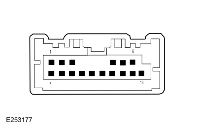
    Upper Clockspring C218B, pin 12 (component side) Upper Clockspring C218B, pin 13 (component side)

      RH Lower Steering Wheel Switch


    Positive Lead Measurement / Action Negative Lead
    Upper Clockspring C218B (Component Side) - Pin 11 Upper Clockspring C218B (Component Side) - Pin 13
    Upper Clockspring C218B (Component Side) - Pin 14 Upper Clockspring C218B (Component Side) - Pin 13

Is the voltage approximately 5 volts?
Yes REPAIR the steering wheel harness (open or short is present) or INSTALL a new steering wheel as necessary.
No GO to AR4

AR4 PERFORM THE SCCM (STEERING COLUMN CONTROL MODULE) SELF-TEST
  • Using a diagnostic scan tool, perform the SCCM self-test.

Are any Diagnostic Trouble Codes (DTCs) recorded?
Yes For DTC B1380:11, GO to AR5
For DTC B1380:13, GO to AR6
For all other SCCM Diagnostic Trouble Codes (DTCs),
REFER to: Steering Wheel and Column Electrical Components (211-05 Steering Wheel and Column Electrical Components, Diagnosis and Testing).
No GO to AR8

AR5 CHECK THE CLOCKSPRING FOR A SHORT TO GROUND
  • Ignition OFF.
  • Remove the clockspring.
    REFER to: Clockspring (501-20B Supplemental Restraint System, Removal and Installation).
  • Ignition ON.
  • NOTE: DTC B1380:11 may be present when carrying out this step and should be disregarded at this time. Using a diagnostic scan tool, carry out the SCCM self-test.

Is DTC B1380:13 present?
Yes INSTALL a new clockspring.
REFER to: Clockspring (501-20B Supplemental Restraint System, Removal and Installation).
No GO to AR8

AR6 CHECK THE MESSAGE CENTER SIGNAL CIRCUITS FOR AN OPEN THROUGH THE CLOCKSPRING
  • Ignition OFF.
  • Remove the clockspring.
    REFER to: Clockspring (501-20B Supplemental Restraint System, Removal and Installation).
  • Measure:

      RH Upper Steering Wheel Switch


    Positive Lead Measurement / Action Negative Lead
    Upper clockspring C218B-12 (component side) 
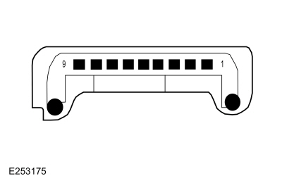
Lower clockspring, pin 6 (component side)

      RH Lower Steering Wheel Switch


    Positive Lead Measurement / Action Negative Lead
    Upper Clockspring C218B (Component Side) - Pin 11 Lower Clockspring (Component Side) - Pin 5
    Upper Clockspring C218B (Component Side) - Pin 14 Lower Clockspring (Component Side) - Pin 8

Is the resistance less than 3 ohms?
Yes GO to AR7
No INSTALL a new clockspring.
REFER to: Clockspring (501-20B Supplemental Restraint System, Removal and Installation).

AR7 CHECK THE MESSAGE CENTER RETURN CIRCUIT FOR AN OPEN THROUGH CLOCKSPRING
  • Measure:
    Positive Lead Measurement / Action Negative Lead
    Upper clockspring C218B-13 (component side) Lower clockspring, pin 7 (component side)

Is the resistance less than 3 ohms?
Yes GO to AR8
No INSTALL a new clockspring.
REFER to: Clockspring (501-20B Supplemental Restraint System, Removal and Installation).

AR8 CHECK FOR CORRECT SCCM (STEERING COLUMN CONTROL MODULE) OPERATION
  • Ignition OFF.
  • Disconnect and inspect the SCCM connectors.
  • Repair:
    • corrosion (install new connector or terminals – clean module pins)
    • damaged or bent pins – install new terminals/pins
    • pushed-out pins – install new pins as necessary
  • Reconnect all the SCCM connectors. Make sure they seat and latch correctly.
  • Operate the system and determine if the concern is still present.

Is the concern still present?
Yes CHECK On-Line Automotive Service Information System (OASIS) for any applicable service articles. TSB , GSB , SSM or FSA . If a service article exists for this concern, DISCONTINUE this test and FOLLOW the service article instructions. If no service articles address this concern, INSTALL a new SCCM .
REFER to: Steering Column Control Module (SCCM) (211-05 Steering Wheel and Column Electrical Components, Removal and Installation).
No The system is operating correctly at this time. The concern may have been caused by module connections. ADDRESS the root cause of any connector or pin issues.

PINPOINT TEST AS: THE DTE (DISTANCE TO EMPTY) DISPLAY IS INCORRECT OR FLUCTUATES

NOTE: The DTE display and the fuel gauge both use the fuel level input from the fuel tank to provide their respective functions. If the fuel gauge doesn't function correctly, both the fuel gauge and the DTE display are affected.

NOTE: The actual DTE can be higher or lower than the DTE displayed in the message center due to changes in driving conditions. It is important to understand how the DTE is calculated and the factors that impact the DTE display when determining how to address any DTE concerns.

NOTE: Even if the fuel economy is relatively constant, the DTE can vary in the short term by up to 80 km (50 miles), but is usually within 16 km (10 miles).

Normal Operation and Fault Conditions

See DTE /Average Fuel Economy (AFE). REFER to: Message Center - System Operation and Component Description (413-01 Instrumentation, Message Center and Warning Chimes, Description and Operation).

The DTE is calculated in the PCM using the PCM internal Running Average Fuel Economy (RAFE), which is the fuel economy over a much longer distance than the Instantaneous Fuel Economy (IFE). The PCM Running Average Fuel Economy (RAFE) is not displayed in the IPC . The IPC shows a static value for Running Average Fuel Economy (RAFE) in Engineering Test mode. The fuel level input from the fuel sender(s), fuel consumption and odometer are used to determine how many miles the vehicle can be driven based on the remaining fuel in the tank. The speedometer signal is required to determine whether a refueling event is detected accurately.

The PCM defaults to a preset baseline L/100km (mpg) Running Average Fuel Economy (RAFE) when the keep alive memory is reset or the PCM is flashed and changes afterward based on driving habits and conditions.

Since the DTE is calculated and averaged over a longer period of time, varying driving conditions can have a significant impact on the current or short term DTE as opposed to the displayed DTE . This difference often leads to customer complaints of incorrect or invalid DTE .

The following list provides some (not all) of the driving conditions that may lead to an incorrect or fluctuating DTE concern:

  • Changing between towing/not towing
  • Changing driving between city and highway
  • Allowing the vehicle to idle for long periods of time
  • Using the remote start feature (if equipped) frequently or allowing the vehicle to warm up, particularly when parked on a grade
  • Parking or driving on grades
  • Inconsistent use of gasoline or E85 fuels
  • Over-fueling or not filling the tank completely (trickle filling at above full, partial refueling with less than 10% of fuel tank capacity)

The PCM uses the following network inputs to control the DTE .

  • Fuel alcohol percent
  • Fuel flow volume
  • Odometer count
  • Transport mode
  • Fuel level input from the IPC

The DTE features the following:

DTE decreases while driving, but can increase if fuel economy improves. After a period of high consumption and entering a state of low consumption, it is possible that DTE will not change for a period of time.

DTE calculation considers the amount of fuel above an empty indication. There is a certain amount of reserve fuel below the empty indication ( DTE equals 0) which allows for a minimal distance of additional driving. This fuel volume is not a specified amount and should not be relied upon.

Possible Sources

  • Fuel gauge concern
  • Changing between city and highway driving
  • Extended idle times
  • Using the remote start feature (if equipped) frequently or allowing the vehicle to warm up, particularly when parked on a grade
  • Parking or driving on grades
  • Inconsistent use of gasoline or E85 fuels
  • Over-fueling or not filling the tank completely (trickle filling at above full, partial refueling with less than 10% of fuel tank capacity)
  • PCM concern
  • IPC configuration

Visual Inspection and Pre-checks

  • If any of the previous conditions occur, the vehicle must be driven over time to allow the DTE calculations to adjust.
AS1 REVIEW AND INVESTIGATE THE FOLLOWING DRIVING CONDITIONS WITH THE CUSTOMER
  • Determine whether the driver changes the following driving conditions:
    • changing between towing/not towing, city/highway driving
    • use of extended idle times
    • use of remote start frequently (if equipped)
    • parking/driving on grades
    • use of E85 fuel exclusively or switching to non-Ethanol fuel
    • over filling the fuel tank or not filling the tank completely (partial refueling)

Does the driver change driving conditions?
Yes Advise the customer how changing driving conditions can affect the current short-term DTE as opposed to the displayed long-term DTE .
The DTE may increase based on significant improvement in fuel economy, such as changing from towing to highway driving, may decrease as expected based on relatively constant fuel economy, or may decrease more than expected due to large reduction in fuel economy, such as changing from highway driving to towing or city driving.
No GO to AS2

AS2 CHECK THE FUEL GAUGE FOR CORRECT OPERATION
  • Ignition ON.
  • Verify the fuel gauge is functioning and correctly indicating the remaining fuel level.

Is the fuel gauge operating correctly?
Yes GO to AS3
No GO to Pinpoint Test C

AS3 RETRIEVE THE RECORDED DIAGNOSTIC TROUBLE CODES (DTCS) FROM THE IPC (INSTRUMENT PANEL CLUSTER) SELF-TEST
  • Using a diagnostic scan tool, perform the IPC self-test.

Are any Diagnostic Trouble Codes (DTCs) recorded?
Yes REFER to the DTC Chart in this section.
No GO to AS4

AS4 PERFORM THE PCM (POWERTRAIN CONTROL MODULE) SELF-TEST
  • Using a diagnostic scan tool, perform the PCM self-test.

Are any Diagnostic Trouble Codes (DTCs) recorded?
Yes REFER to the Master DTC Chart.
No GO to AS5

AS5 PERFORM THE BCM (BODY CONTROL MODULE) SELF-TEST
  • Using a diagnostic scan tool, perform the BCM self-test.

Are any Diagnostic Trouble Codes (DTCs) recorded?
Yes REFER to the Master DTC Chart.
No The vehicle configuration is most likely incorrect for the fuel tank size. INSTALL As-Built data from PTS following scan tool instructions.

PINPOINT TEST AT: THE DTE (DISTANCE TO EMPTY) DISPLAY IS INOPERATIVE

Normal Operation and Fault Conditions

See DTE . REFER to: Message Center - System Operation and Component Description (413-01 Instrumentation, Message Center and Warning Chimes, Description and Operation).

Possible Sources

  • Communication concern
  • IPC
AT1 VERIFY OPERATION OF THE FUEL GAUGE
  • Ignition ON.
  • Verify operation of the fuel gauge.

Does the fuel gauge operate properly?
Yes GO to AT2
No GO to Pinpoint Test C

AT2 VERIFY OPERATION OF THE SPEEDOMETER
  • Verify operation of the speedometer.

Does the speedometer operate properly?
Yes GO to AT3
No GO to Pinpoint Test D

AT3 VERIFY OPERATION OF THE ODOMETER
  • Verify operation of the odometer.

Does the odometer operate properly?
Yes GO to AT4
No GO to Pinpoint Test E

AT4 CHECK FOR CORRECT IPC (INSTRUMENT PANEL CLUSTER) OPERATION
  • Ignition OFF.
  • Disconnect and inspect the IPC connector.
  • Repair:
    • corrosion (install new connector or terminals – clean module pins)
    • damaged or bent pins – install new terminals/pins
    • pushed-out pins – install new pins as necessary
  • Reconnect the IPC connector. Make sure it seats and latches correctly.
  • Operate the system and determine if the concern is still present.

Is the concern still present?
Yes CHECK OASIS for any applicable service articles: TSB , GSB , SSM or FSA . If a service article exists for this concern, DISCONTINUE this test and FOLLOW the service article instructions. If no service articles address this concern, INSTALL a new IPC .
REFER to: Instrument Panel Cluster (IPC) (413-01 Instrumentation, Message Center and Warning Chimes, Removal and Installation).
No The system is operating correctly at this time. The concern may have been caused by module connections. ADDRESS the root cause of any connector or pin issues.

PINPOINT TEST AU: THE OFF ROAD DISPLAY IS INOPERATIVE

Normal Operation and Fault Conditions

See Drive Mode (Off Road) Display. REFER to: Message Center - System Operation and Component Description (413-01 Instrumentation, Message Center and Warning Chimes, Description and Operation).

If the 4x4 high/low status, vehicle pitch angle display, vehicle roll angle display and steering wheel angle messages are missing for less than 5 seconds, the IPC defaults the associated display element to the last display based on the last data received.

If the 4x4 high/low status, vehicle pitch angle display, vehicle roll angle display and steering wheel angle messages are missing for 5 seconds or longer, the IPC sets a lost communication DTC for the module in question and defaults the associated display element off or blank.

Possible Sources

  • Communication concern
  • ABS module concern
  • GWM concern
  • PSCM concern
  • TCCM concern
  • IPC
AU1 VERIFY THE IPC (INSTRUMENT PANEL CLUSTER) IS SET TO THE OFF ROAD DISPLAY SCREEN
  • Ignition ON.
  • NOTE: The IPC and message center navigation can be found in the Owner's Literature. Using the message center controls, make sure the IPC is set to the off road display screen.

Is the IPC set to the off road display screen?
Yes GO to AU2
No The off road display is operating correctly. The IPC was not set to the correct display screen.

AU2 PERFORM THE TCCM (TRANSFER CASE CONTROL MODULE) SELF-TEST
  • Using a diagnostic scan tool, perform the TCCM self-test.
  • Check for recorded Diagnostic Trouble Codes (DTCs).

Are any Diagnostic Trouble Codes (DTCs) recorded?
Yes
REFER to: DTC Chart and Pinpoint Tests - Vehicles With: 1-Speed Torque On Demand Transfer Case (307-07A Four-Wheel Drive Systems, Diagnosis and Testing).
or REFER to: DTC Chart and Pinpoint Tests - Vehicles With: 2-Speed Torque On Demand Transfer Case (307-07A Four-Wheel Drive Systems, Diagnosis and Testing).
No GO to AU3

AU3 PERFORM THE ABS (ANTI-LOCK BRAKE SYSTEM) MODULE SELF-TEST
  • Using a diagnostic scan tool, perform the ABS module self-test.
  • Check for recorded Diagnostic Trouble Codes (DTCs).

Are any Diagnostic Trouble Codes (DTCs) recorded?
Yes
REFER to: Anti-Lock Brake System (ABS) and Stability Control (206-09 Anti-Lock Brake System (ABS) and Stability Control, Diagnosis and Testing).
No GO to AU4

AU4 PERFORM THE PSCM (POWER STEERING CONTROL MODULE) SELF-TEST
  • Using a diagnostic scan tool, perform the PSCM self-test.
  • Check for recorded Diagnostic Trouble Codes (DTCs).

Are any Diagnostic Trouble Codes (DTCs) recorded?
Yes
REFER to: Power Steering (211-02 Power Steering, Diagnosis and Testing).
No GO to AU5

AU5 CHECK THE GWM (GATEWAY MODULE A) DIAGNOSTIC TROUBLE CODES (DTCS)
  • Using a diagnostic scan tool, check the GWM Continuous Memory Diagnostic Trouble Codes (CMDTCs).

Are any Diagnostic Trouble Codes (DTCs) recorded?
Yes
REFER to: Controller Area Network (CAN) Module Communications Network (418-00A Controller Area Network (CAN) Module Communications Network, Diagnosis and Testing).
No GO to AU6

AU6 CHECK FOR CORRECT IPC (INSTRUMENT PANEL CLUSTER) OPERATION
  • Ignition OFF.
  • Disconnect and inspect the IPC connector.
  • Repair:
    • corrosion (install new connector or terminals – clean module pins)
    • damaged or bent pins – install new terminals/pins
    • pushed-out pins – install new pins as necessary
  • Reconnect the IPC connector. Make sure it seats and latches correctly.
  • Operate the system and determine if the concern is still present.

Is the concern still present?
Yes CHECK OASIS for any applicable service articles: TSB , GSB , SSM or FSA . If a service article exists for this concern, DISCONTINUE this test and FOLLOW the service article instructions. If no service articles address this concern, INSTALL a new IPC .
REFER to: Instrument Panel Cluster (IPC) (413-01 Instrumentation, Message Center and Warning Chimes, Removal and Installation).
No The system is operating correctly at this time. The concern may have been caused by module connections. ADDRESS the root cause of any connector or pin issues.

PINPOINT TEST AV: THE OUTSIDE AIR TEMPERATURE DISPLAY IS INOPERATIVE OR INCORRECT

Normal Operation and Fault Conditions

See Outside Air Temperature. REFER to: Message Center - System Operation and Component Description (413-01 Instrumentation, Message Center and Warning Chimes, Description and Operation).

If the outside air temperature status message is missing or invalid for less than 5 seconds, the IPC defaults the outside air temperature display to the last temperature reading, based upon the last message received.

If the outside air temperature status message is missing or invalid for 5 seconds or longer from the FCIM , the IPC displays all dashes (- - - -) in the outside air temperature display area.

DTC Fault Trigger Conditions

DTC Description Fault Trigger Condition
PCM P0071:00 Ambient Air Temperature Sensor Circuit 'A' Range/Performance: No Sub Type Information Sets when the PCM detects the ambient air temperature sensor reading does not correlate with the other temperature sensor readings at ignition ON. The PCM runs this logic after an engine off and a calibrated soak period, typically 6 to 8 hours. This soak period allows the ambient air temperature sensor and the other temperature sensors to stabilize and not differ by greater than a calibrated value, typically 18° C (32.4° F).
PCM P0072:00 Ambient Air Temperature Sensor Circuit 'A' Low: No Sub Type Information Sets when the PCM detects the ambient air temperature sensor signal is less than the self-test minimum.
PCM P0073:00 Ambient Air Temperature Sensor Circuit 'A' High: No Sub Type Information Sets when the PCM detects the ambient air temperature sensor signal is greater than the self-test maximum.
PCM P0074:00 Ambient Air Temperature Sensor Circuit 'A' Intermittent/Erratic: No Sub Type Information Sets when the PCM detects the ambient air temperature sensor signal changes beyond the minimum or maximum calibrated limit.

Possible Sources

  • Communication concern
  • Ambient air temperature sensor input to the PCM
  • GWM
  • FCIM
AV1 PERFORM THE IPC (INSTRUMENT PANEL CLUSTER) SELF-TEST
  • Ignition ON.
  • Using a diagnostic scan tool, perform the IPC self-test.

Are any Diagnostic Trouble Codes (DTCs) recorded?
Yes REFER to the DTC Chart in this section.
No GO to AV2

AV2 PERFORM THE FCIM (FRONT CONTROLS INTERFACE MODULE) SELF-TEST
  • Using a diagnostic scan tool, perform the HVAC module self-test.

Are any Diagnostic Trouble Codes (DTCs) recorded?
Yes REFER to the Master DTC Chart.
No GO to AV3

AV3 CHECK THE GWM (GATEWAY MODULE A) DIAGNOSTIC TROUBLE CODES (DTCS)
  • Using a diagnostic scan tool, check the GWM Continuous Memory Diagnostic Trouble Codes (DTCs).

Are any Diagnostic Trouble Codes (DTCs) recorded?
Yes
REFER to: Controller Area Network (CAN) Module Communications Network (418-00A Controller Area Network (CAN) Module Communications Network, Diagnosis and Testing).
No GO to AV4

AV4 PERFORM THE PCM (POWERTRAIN CONTROL MODULE) SELF-TEST
  • Using a diagnostic scan tool, perform the PCM self-test.

Are any Diagnostic Trouble Codes (DTCs) recorded?
Yes REFER to the Master DTC Chart.
No GO to AV5

AV5 CHECK THE AMBIENT AIR TEMPERATURE INPUT TO THE PCM (POWERTRAIN CONTROL MODULE)
  • Allow the vehicle to sit out of the sun with the engine off, for approximately 6 hours to remove any potential heat soak at the ambient air temperature sensor.
  • Using a diagnostic scan tool, view the PCM Parameter Identifications (PIDs).
  • Access the  PCM  and monitor the  AAT (Deg C)  PID

  • Monitor the ambient air temperature PID and compare the PID value with the actual outside air temperature.

Does the ambient air temperature match the actual outside air temperature?
Yes GO to AV6
No GO to AV7

AV6 CHECK THE OUTSIDE AIR TEMPERATURE DISPLAY UPDATE
  • NOTE: Always drive the vehicle in a safe manner according to driving conditions and obey all traffic laws. Drive the vehicle above 33 km/h (20 mph) to allow the outside air temperature display to update.

Did the outside air temperature display update toward the actual ambient air temperature?
Yes The system is operating correctly at this time. Explain to the customer the operation of the system as it relates to the update strategy.
No DIAGNOSE the FCIM .
REFER to: Climate Control System (412-00 Climate Control System - General Information, Diagnosis and Testing).

AV7 CHECK THE AMBIENT AIR TEMPERATURE SENSOR RESISTANCE
  • Ignition OFF.
  • Disconnect PCM C175B .
  • Measure:
    Click to display connectors
    Positive Lead Measurement / Action Negative Lead
      C175B-36   C175B-40
  • Compare the ambient temperature sensor resistances using the table below.
    Outside Air Temperature Ambient Air Temperature Sensor Value
    Celcius Fahrenheit Resistance (K ohms)
    -1.1° to 4.4° 30° to 40° 27.49 to 33.47
    4.4° to 10° 40° to 50° 22.06 to 28.86
    10° to 15.6° 50° to 60° 16.63 to 23.10
    15.6° to 21.1° 60° to 70° 11.74 to 17.32
    21.1° to 26.7° 70° to 80° 9.34 to 12.14
    26.7° to 32.2° 80° to 90° 8.49 to 9.62
    32.2° to 37.8° 90° to 100° 5.93 to 7.87
    37.8° to 43.3° 100° to 110° 4.78 to 6.11

Does the resistance match the table specifications above?
Yes GO to AV9
No GO to AV8

AV8 CHECK THE AMBIENT AIR TEMPERATURE SENSOR RESISTANCE
  • Disconnect Ambient Air Temperature Sensor C132 .
  • Measure:
    Positive Lead Measurement / Action Negative Lead
      C132-1   C132-2
  • Compare the ambient temperature sensor resistances using the table below.
    Outside Air Temperature Ambient Air Temperature Sensor Value
    Celcius Fahrenheit Resistance (K ohms)
    -1.1° to 4.4° 30° to 40° 27.49 to 33.47
    4.4° to 10° 40° to 50° 22.06 to 28.86
    10° to 15.6° 50° to 60° 16.63 to 23.10
    15.6° to 21.1° 60° to 70° 11.74 to 17.32
    21.1° to 26.7° 70° to 80° 9.34 to 12.14
    26.7° to 32.2° 80° to 90° 8.49 to 9.62
    32.2° to 37.8° 90° to 100° 5.93 to 7.87
    37.8° to 43.3° 100° to 110° 4.78 to 6.11

Does the resistance match the table specifications above?
Yes The ambient air temperature sensor is operating correctly. REPAIR the circuits for high circuit resistance.
No GO to AV10

AV9 CHECK THE AMBIENT AIR TEMPERATURE SENSOR FOR OBSTRUCTIONS OR DEBRIS
  • Check the area around the ambient air temperature sensor for any obstructions or debris such as leaves or paper.

Is the area around the ambient air temperature sensor free from any obstructions or debris?
Yes GO to AV10
No CLEAR all debris or obstructions as necessary to allow for the free flow of air around the ambient air temperature sensor.

AV10 CHECK THE AMBIENT AIR TEMPERATURE SENSOR OPERATION
  • Ignition OFF.
  • Inspect the connector and wiring:
    • water intrusion
    • corrosion
    • damaged pins
    • pushed-out pins

Are there any signs of water intrusion, corrosion, damaged or pushed out pins?
Yes REPAIR the ambient air temperature sensor connector or wiring for any water intrusion, corrosion, damaged or pushed out pins.
No INSTALL a new ambient air temperature sensor.
REFER to: Ambient Air Temperature Sensor (412-00 Climate Control System - General Information, Removal and Installation).

PINPOINT TEST AW: THE SPEED SIGN RECOGNITION DISPLAY IS INOPERATIVE

Normal Operation and Fault Conditions

See Speed Sign Recognition. REFER to: Instrument Panel Cluster (IPC) - System Operation and Component Description (413-01 Instrumentation, Message Center and Warning Chimes, Description and Operation).

If the traffic sign recognition status request message is missing for less than 5 seconds, the IPC defaults the speed limit sign display to its last indication state (on or off), based upon the last message received.

If the traffic sign recognition status request message is missing for 5 seconds or longer, the IPC defaults the speed limit sign display off.

Possible Sources

  • Communication concern
  • IPMA concern
  • GWM
  • IPC
AW1 CHECK THE MESSAGE CENTER OPERATION
  • Ignition ON.
  • Close all doors, hood and the liftgate.
  • Clear all message center warnings by pressing the OK button for each warning present.
  • Monitor the door ajar RTT .
  • Open the driver door.
  • Clear the message center popup warning.
  • Monitor the door ajar RTT .

Is the door ajar RTT off with the door closed, and on with the door open?
Yes GO to AW2
No GO to Pinpoint Test A

AW2 PERFORM THE IPC (INSTRUMENT PANEL CLUSTER) SELF-TEST
  • Ignition ON.
  • Using a diagnostic scan tool, perform the IPC self-test.

Are any Diagnostic Trouble Codes (DTCs) recorded?
Yes REFER to the DTC Chart in this section.
No GO to AW3

AW3 PERFORM THE IPMA (IMAGE PROCESSING MODULE A) SELF-TEST
  • Using a diagnostic scan tool, perform the IPMA self-test.

Are any Diagnostic Trouble Codes (DTCs) recorded?
Yes REFER to the Master DTC Chart.
No GO to AW4

AW4 CHECK THE GWM (GATEWAY MODULE A) DIAGNOSTIC TROUBLE CODES (DTCS)
  • Using a diagnostic scan tool, check the GWM Continuous Memory Diagnostic Trouble Codes (DTCs).

Are any Diagnostic Trouble Codes (DTCs) recorded?
Yes
REFER to: Controller Area Network (CAN) Module Communications Network (418-00A Controller Area Network (CAN) Module Communications Network, Diagnosis and Testing).
No DIAGNOSE the front camera.
REFER to: Lane Keeping System (419-07 Lane Keeping System, Diagnosis and Testing).

PINPOINT TEST AX: THE TPMS (TIRE PRESSURE MONITORING SYSTEM) DISPLAY IS INOPERATIVE OR INCORRECT

Normal Operation and Fault Conditions

See TPMS . REFER to: Message Center - System Operation and Component Description (413-01 Instrumentation, Message Center and Warning Chimes, Description and Operation).

Possible Sources

  • TPMS
  • TPMS display
  • IPC
AX1 VERIFY THE TPMS (TIRE PRESSURE MONITORING SYSTEM) DISPLAY IS SET TO OPERATE
  • Verify the message center is set to display the TPMS tire pressures. REFER to the Owner's Literature for message center navigation.

Is the message center set to display the TPMS tire pressures?
Yes DIAGNOSE the TPMS warning indicator. GO to Pinpoint Test AQ
No EXPLAIN to the customer how to navigate the message center menu to display the TPMS tire pressures.

PINPOINT TEST AY: THE TRAILER INFORMATION DISPLAY IS INOPERATIVE

Normal Operation and Fault Conditions

See Trailer Information Display. REFER to: Message Center - System Operation and Component Description (413-01 Instrumentation, Message Center and Warning Chimes, Description and Operation).

If the gear lever position, vehicle speed, ignition status, trailer setup, trailer reverse message request, BLIS trailer tow left or BLIS trailer tow right messages are missing for less than 5 seconds, the IPC defaults the display to its current state based upon the last message received

If the gear lever position, vehicle speed, ignition status, trailer setup, trailer reverse message request, BLIS trailer tow left or BLIS trailer tow right messages are missing for 5 seconds or longer, the IPC sets a DTC for the module in question and defaults the associated display element off or blank.

Possible Sources

  • Communication concern
  • BCM concern
  • GWM concern
  • PCM concern
  • IPMA concern
  • IPC
AY1 VERIFY THE IPC (INSTRUMENT PANEL CLUSTER) IS SET TO THE TRAILER INFORMATION DISPLAY SCREEN
  • Ignition ON.
  • NOTE: The IPC and message center navigation can be found in the Owner's Literature. Using the message center controls, make sure the IPC is set to the trailer information display screen.

Is the IPC set to the trailer information display screen?
Yes GO to AY2
No The trailer information display is operating correctly. The IPC was not set to the correct display screen.

AY2 PERFORM THE PCM (POWERTRAIN CONTROL MODULE) KOEO (KEY ON, ENGINE OFF) SELF-TEST
  • Using a diagnostic scan tool, perform the PCM KOEO self-test.
  • Check for recorded Diagnostic Trouble Codes (DTCs).

Are any Diagnostic Trouble Codes (DTCs) recorded?
Yes REFER to the Master DTC Chart.
No GO to AY3

AY3 PERFORM THE BCM (BODY CONTROL MODULE) SELF-TEST
  • Using a diagnostic scan tool, perform the BCM self-test.
  • Check for recorded Diagnostic Trouble Codes (DTCs).

Are any Diagnostic Trouble Codes (DTCs) recorded?
Yes REFER to the Master DTC Chart.
No GO to AY4

AY4 PERFORM THE IPMA (IMAGE PROCESSING MODULE A) SELF-TEST
  • Using a diagnostic scan tool, perform the IPMA self-test.
  • Check for recorded Diagnostic Trouble Codes (DTCs).

Are any Diagnostic Trouble Codes (DTCs) recorded?
Yes REFER to the Master DTC Chart.
No GO to AY5

AY5 CHECK THE GWM (GATEWAY MODULE A) DIAGNOSTIC TROUBLE CODES (DTCS)
  • Using a diagnostic scan tool, check the GWM Continuous Memory Diagnostic Trouble Codes (CMDTCs).

Are any Diagnostic Trouble Codes (DTCs) recorded?
Yes
REFER to: Controller Area Network (CAN) Module Communications Network (418-00A Controller Area Network (CAN) Module Communications Network, Diagnosis and Testing).
No GO to AY6

AY6 CHECK FOR CORRECT IPC (INSTRUMENT PANEL CLUSTER) OPERATION
  • Ignition OFF.
  • Disconnect and inspect the IPC connector.
  • Repair:
    • corrosion (install new connector or terminals – clean module pins)
    • damaged or bent pins – install new terminals/pins
    • pushed-out pins – install new pins as necessary
  • Reconnect the IPC connector. Make sure it seats and latches correctly.
  • Operate the system and determine if the concern is still present.

Is the concern still present?
Yes CHECK OASIS for any applicable service articles: TSB , GSB , SSM or FSA . If a service article exists for this concern, DISCONTINUE this test and FOLLOW the service article instructions. If no service articles address this concern, INSTALL a new IPC .
REFER to: Instrument Panel Cluster (IPC) (413-01 Instrumentation, Message Center and Warning Chimes, Removal and Installation).
No The system is operating correctly at this time. The concern may have been caused by module connections. ADDRESS the root cause of any connector or pin issues.

PINPOINT TEST AZ: THE TRAILER LIGHTING DISPLAY IS INOPERATIVE

Normal Operation and Fault Conditions

See Trailer Lighting Display. REFER to: Message Center - System Operation and Component Description (413-01 Instrumentation, Message Center and Warning Chimes, Description and Operation).

If the parklamp status, trailer lamp connected, trailer turn indicator status or trailer lamp out messages are missing for less than 5 seconds, the IPC defaults the display to the last displayed state based upon the last message received.

If the parklamp status, trailer lamp connected, trailer turn indicator status or trailer lamp out messages are missing for 5 seconds or longer, the IPC sets a DTC for the module in question and defaults the associated display element off or blank.

Possible Sources

  • Communication concern
  • BCM concern
  • GWM concern
  • TRM concern
  • IPC
AZ1 VERIFY THE IPC (INSTRUMENT PANEL CLUSTER) IS SET TO THE TRAILER LIGHTING DISPLAY SCREEN
  • Ignition ON.
  • NOTE: The IPC and message center navigation can be found in the Owner's Literature. Using the message center controls, make sure the IPC is set to the trailer lighting display screen.

Is the IPC set to the trailer lighting display screen?
Yes GO to AZ2
No The trailer lighting display is operating correctly. The IPC was not set to the correct display screen.

AZ2 PERFORM THE IPC (INSTRUMENT PANEL CLUSTER) SELF-TEST
  • Using a diagnostic scan tool, perform the IPC self-test.
  • Check for recorded Diagnostic Trouble Codes (DTCs).

Are any Diagnostic Trouble Codes (DTCs) recorded?
Yes REFER to the DTC Chart in this section.
No GO to AZ3

AZ3 PERFORM THE BCM (BODY CONTROL MODULE) SELF-TEST
  • Using a diagnostic scan tool, perform the BCM self-test.
  • Check for recorded Diagnostic Trouble Codes (DTCs).

Are any Diagnostic Trouble Codes (DTCs) recorded?
Yes REFER to the Master DTC Chart.
No GO to AZ4

AZ4 PERFORM THE TRM (TRAILER MODULE) SELF-TEST
  • Using a diagnostic scan tool, perform the TRM self-test.
  • Check for recorded Diagnostic Trouble Codes (DTCs).

Are any Diagnostic Trouble Codes (DTCs) recorded?
Yes
REFER to: Trailer Lamps (417-01 Exterior Lighting, Diagnosis and Testing).
No GO to AZ5

AZ5 CHECK THE GWM (GATEWAY MODULE A) DIAGNOSTIC TROUBLE CODES (DTCS)
  • Using a diagnostic scan tool, check the GWM Continuous Memory Diagnostic Trouble Codes (CMDTCs).

Are any Diagnostic Trouble Codes (DTCs) recorded?
Yes
REFER to: Controller Area Network (CAN) Module Communications Network (418-00A Controller Area Network (CAN) Module Communications Network, Diagnosis and Testing).
No DIAGNOSE the trailer lighting system.
REFER to: Trailer Lamps (417-01 Exterior Lighting, Diagnosis and Testing).

PINPOINT TEST BA: THE CHECK FUEL FILL INLET MESSAGE IS ALWAYS DISPLAYED

Normal Operation and Fault Conditions

See Check Fuel Fill Inlet Message. REFER to: Message Center - System Operation and Component Description (413-01 Instrumentation, Message Center and Warning Chimes, Description and Operation).

If the check fuel fill inlet message display is missing for less than 5 seconds, the IPC defaults the check fuel fill inlet message center message to the last indication state, based upon the last message received.

If the check fuel fill inlet message display is missing for 5 seconds or longer, the IPC defaults the check fuel fill inlet message center message off.

Possible Sources

  • Evaporative emissions system concern
  • GWM
  • PCM
  • IPC
BA1 CHECK THE MESSAGE CENTER OPERATION
  • Ignition ON.
  • Close all doors, hood and the liftgate.
  • Clear all message center warnings by pressing the OK button for each warning present.
  • Monitor the door ajar RTT warning indicator.
  • Open the driver door.
  • Clear the message center popup warning.
  • Monitor the door ajar RTT warning indicator.

Is the door ajar RTT warning indicator off with the door closed, and on with the door open?
Yes GO to BA2
No GO to Pinpoint Test A

BA2 PERFORM THE IPC (INSTRUMENT PANEL CLUSTER) SELF-TEST
  • Using a diagnostic scan tool, perform the IPC self-test.

Are any Diagnostic Trouble Codes (DTCs) recorded?
Yes REFER to the DTC Chart in this section.
No GO to BA3

BA3 CHECK THE GWM (GATEWAY MODULE A) DIAGNOSTIC TROUBLE CODES (DTCS)
  • Using a diagnostic scan tool, check the GWM Continuous Memory Diagnostic Trouble Codes (DTCs).

Are any Diagnostic Trouble Codes (DTCs) recorded?
Yes
REFER to: Controller Area Network (CAN) Module Communications Network (418-00A Controller Area Network (CAN) Module Communications Network, Diagnosis and Testing).
No If the check fuel fill inlet message is never on, the system is operating correctly at this time. There are currently no vehicle concerns present that require the check fuel fill inlet message display.
If the check fuel fill inlet message is always on, DIAGNOSE all PCM Diagnostic Trouble Codes (DTCs). REFER to the Master DTC Chart.

PINPOINT TEST BB: THE ENGINE OIL CHANGE MESSAGE IS ALWAYS DISPLAYED

Normal Operation and Fault Conditions

See Engine Oil Life Display. REFER to: Message Center - System Operation and Component Description (413-01 Instrumentation, Message Center and Warning Chimes, Description and Operation).

Possible Sources

  • Engine oil life requires reset
  • Message center switch concern
  • PCM
  • GWM concern
  • IPC
BB1 CHECK THE MESSAGE CENTER SWITCH OPERATION
  • Ignition OFF.
  • Close all doors, hood and the liftgate.
  • Ignition ON.
  • Once the IPC has completed its prove-out and is in normal operation mode, open the driver door.
  • Press the OK button to clear the door ajar warning message.

Does the door ajar warning message clear?
Yes GO to BB2
No DIAGNOSE the message center switch. GO to Pinpoint Test AR

BB2 RESET THE ENGINE OIL LIFE
  • NOTE: For message center menu navigation to reset the oil life, refer to the Owner's Literature. Using the message center, reset the engine oil life.

Does the engine oil change message clear?
Yes The system is operating correctly. EXPLAIN to the customer how to reset the engine oil life.
No GO to BB3

BB3 PERFORM THE IPC (INSTRUMENT PANEL CLUSTER) SELF-TEST
  • Using a diagnostic scan tool, perform the IPC self-test.

Are any Diagnostic Trouble Codes (DTCs) recorded?
Yes REFER to the DTC Chart in this section.
No GO to BB4

BB4 PERFORM THE PCM (POWERTRAIN CONTROL MODULE) KOEO (KEY ON, ENGINE OFF) SELF-TEST
  • Ignition ON.
  • Using a diagnostic scan tool, perform the PCM KOEO self-test.

Are any Diagnostic Trouble Codes (DTCs) recorded?
Yes REFER to the Master DTC Chart.
No GO to BB5

BB5 CHECK FOR RECENT SERVICE HISTORY
  • CHECK the vehicle service history for recent service actions related to PCM or IPC software updates.

Was the software updated in either the PCM or IPC ?
Yes CHECK OASIS for any applicable service articles: TSB , GSB , SSM or FSA . If a service article exists for this concern, DISCONTINUE this test and FOLLOW the service article instructions. If no service articles address this concern, UPDATE the software in the module in question.
ATTEMPT to reset the engine oil life again. If the engine oil change message cannot be cleared:
For the PCM , GO to BB6
For the IPC , GO to BB7
No GO to BB6
If the engine oil life still cannot be reset, GO to BB7

BB6 CHECK FOR CORRECT PCM (POWERTRAIN CONTROL MODULE) OPERATION
  • Ignition OFF.
  • Disconnect and inspect the PCM connectors.
  • Repair:
    • corrosion (install new connector or terminals – clean module pins)
    • damaged or bent pins – install new terminals/pins
    • pushed-out pins – install new pins as necessary
  • Reconnect the PCM connector. Make sure thet seat and latch correctly.
  • Operate the system and determine if the concern is still present.

Is the concern still present?
Yes CHECK OASIS for any applicable service articles: TSB , GSB , SSM or FSA . If a service article exists for this concern, DISCONTINUE this test and FOLLOW the service article instructions. If no service articles address this concern,
   Click here to access Guided Routine (PCM).
No The system is operating correctly at this time. The concern may have been caused by module connections. ADDRESS the root cause of any connector or pin issues.

BB7 CHECK FOR CORRECT IPC (INSTRUMENT PANEL CLUSTER) OPERATION
  • Ignition OFF.
  • Disconnect and inspect the IPC connector.
  • Repair:
    • corrosion (install new connector or terminals – clean module pins)
    • damaged or bent pins – install new terminals/pins
    • pushed-out pins – install new pins as necessary
  • Reconnect the IPC connector. Make sure it seats and latches correctly.
  • Operate the system and determine if the concern is still present.

Is the concern still present?
Yes CHECK OASIS for any applicable service articles: TSB , GSB , SSM or FSA . If a service article exists for this concern, DISCONTINUE this test and FOLLOW the service article instructions. If no service articles address this concern, INSTALL a new IPC .
REFER to: Instrument Panel Cluster (IPC) (413-01 Instrumentation, Message Center and Warning Chimes, Removal and Installation).
No The system is operating correctly at this time. The concern may have been caused by module connections. ADDRESS the root cause of any connector or pin issues.

PINPOINT TEST BC: THE ENGINE OIL LIFE MESSAGE IS NEVER DISPLAYED

Normal Operation and Fault Conditions

See Engine Oil Life message. REFER to: Message Center - System Operation and Component Description (413-01 Instrumentation, Message Center and Warning Chimes, Description and Operation).

Possible Sources

  • Message center concern
  • The PCM has not reached the programmed mileage/time based on the criteria required to display the message.
BC1 VERIFY MESSAGE CENTER OPERATION
  • Ignition ON.
  • Open then close the driver door while observing the message center.

Does the driver door ajar message appear in the message center with the driver door ajar and turn off with the driver door closed?
Yes GO to BC2
No GO to Pinpoint Test A

BC2 VERIFY ENGINE OIL LIFE
  • Ignition ON.
  • Using the system check in the message center, verify the engine oil life is between 1% and 5% for the CHANGE ENGINE OIL SOON message or at 0% for the OIL CHANGE REQUIRED message.

Is the engine oil life is between 1% and 5% for the CHANGE ENGINE OIL SOON message or at 0% for the OIL CHANGE REQUIRED message?
Yes GO to BC3
No The system is operating correctly at this time. INFORM the customer how the message center functions and how the engine oil life messages are set.

BC3 CHECK FOR CORRECT IPC (INSTRUMENT PANEL CLUSTER) OPERATION
  • Ignition OFF.
  • Disconnect and inspect the IPC connector.
  • Repair:
    • corrosion (install new connector or terminals – clean module pins)
    • damaged or bent pins – install new terminals/pins
    • pushed-out pins – install new pins as necessary
  • Reconnect the IPC connector. Make sure it seats and latches correctly.
  • Operate the system and determine if the concern is still present.

Is the concern still present?
Yes CHECK OASIS for any applicable service articles: TSB , GSB , SSM or FSA . If a service article exists for this concern, DISCONTINUE this test and FOLLOW the service article instructions. If no service articles address this concern, INSTALL a new IPC .
REFER to: Instrument Panel Cluster (IPC) (413-01 Instrumentation, Message Center and Warning Chimes, Removal and Installation).
No The system is operating correctly at this time. The concern may have been caused by module connections. ADDRESS the root cause of any connector or pin issues.

PINPOINT TEST BD: A TIRE TRAINING MESSAGE IS NEVER ON OR TIRES NOT TRAINED MESSAGE IS ALWAYS ON

NOTE: This message only appears during the TPMS sensor training procedure.

Normal Operation and Fault Conditions

See TPMS . REFER to: Message Center - System Operation and Component Description (413-01 Instrumentation, Message Center and Warning Chimes, Description and Operation).

Possible Sources

  • TPMS warning indicator concern
  • TPMS sensor training concern
BD1 VERIFY THE TPMS (TIRE PRESSURE MONITORING SYSTEM) WARNING INDICATOR FUNCTIONS
  • Ignition ON.
  • Verify the TPMS warning indicator functions.

Does the TPMS warning indicator function?
Yes
REFER to: Tire Pressure Monitoring System (TPMS) Sensor Location Calibration (204-04B Tire Pressure Monitoring System (TPMS), General Procedures).
No GO to Pinpoint Test AQ

PINPOINT TEST BE: THE CHIME ALWAYS SOUNDS

Refer to Wiring Diagrams Cell 60 for schematic and connector information.

Normal Operation and Fault Conditions

REFER to: Warning Chimes - System Operation and Component Description (413-01 Instrumentation, Message Center and Warning Chimes, Description and Operation).

Possible Sources

  • Exterior lighting concern
  • Interior lighting concern
  • Wiring, terminals or connectors
  • Ignition switch
  • BCM
  • GWM
  • IPC
BE1 CHECK THE IPC (INSTRUMENT PANEL CLUSTER) FOR MESSAGE CENTER MESSAGES
  • Ignition OFF.
  • Ignition ON.
  • Check the IPC and message center for illuminated warning indicator or message center displays.

Does the IPC have any RTT indicators illuminated or message center messages displayed?
Yes REPAIR all message center indication concerns first. REFER to Symptom Chart: Indicators and Reconfigurable Telltales (RTTs) or Symptom Chart: Message Center.
No GO to BE2

BE2 CHECK THE EXTERIOR LIGHTING OPERATION
  • Place the headlamp switch in the OFF position.
  • Close all doors and the liftgate.
  • Wait one minute.
  • Observe the exterior lights.

Are the headlamps off?
Yes GO to BE3
No
REFER to: Headlamps (417-01 Exterior Lighting, Diagnosis and Testing).

BE3 CHECK THE INTERIOR LIGHTING OPERATION
  • Open and close the driver door.
  • Observe the interior lights.

Do the interior lights operate correctly from the driver door?
Yes GO to BE4
No
REFER to: Interior Lighting (417-02 Interior Lighting, Diagnosis and Testing).

BE4 PERFORM THE BCM (BODY CONTROL MODULE) SELF-TEST
  • Using a diagnostic scan tool, perform the BCM self-test.

Are any Diagnostic Trouble Codes (DTCs) recorded?
Yes REFER to the Master DTC Chart.
No GO to BE5

BE5 CHECK THE BCM (BODY CONTROL MODULE) INPUT PIDS FROM THE IGNITION SWITCH
  • Using a diagnostic scan tool, view the BCM Parameter Identifications (PIDs).
  • Access the  BCM  and monitor the  IGN_SW_STATE  PID

  • Select and monitor the BCM ignition switch PID while cycling the ignition switch through the ACC, OFF, and RUN states.

Does the BCM PID match the ignition switch positions?
Yes GO to BE6
No For ignition RUN or ACC concerns, DIAGNOSE the ignition switch outputs to the BCM .
REFER to: Steering Wheel and Column Electrical Components (211-05 Steering Wheel and Column Electrical Components, Diagnosis and Testing).

BE6 CHECK FOR CORRECT IPC (INSTRUMENT PANEL CLUSTER) OPERATION
  • Ignition OFF.
  • Disconnect and inspect the IPC connector.
  • Repair:
    • corrosion (install new connector or terminals – clean module pins)
    • damaged or bent pins – install new terminals/pins
    • pushed-out pins – install new pins as necessary
  • Reconnect the IPC connector. Make sure it seats and latches correctly.
  • Operate the system and determine if the concern is still present.

Is the concern still present?
Yes CHECK OASIS for any applicable service articles: TSB , GSB , SSM or FSA . If a service article exists for this concern, DISCONTINUE this test and FOLLOW the service article instructions. If no service articles address this concern, INSTALL a new IPC .
REFER to: Instrument Panel Cluster (IPC) (413-01 Instrumentation, Message Center and Warning Chimes, Removal and Installation).
No The system is operating correctly at this time. The concern may have been caused by module connections. ADDRESS the root cause of any connector or pin issues.

PINPOINT TEST BF: THE CHIME ONLY SOUNDS FROM THE IPC (INSTRUMENT PANEL CLUSTER)

Refer to Wiring Diagrams Cell 60 for schematic and connector information.

Normal Operation and Fault Conditions

REFER to: Warning Chimes - System Operation and Component Description (413-01 Instrumentation, Message Center and Warning Chimes, Description and Operation).

Possible Sources

  • Message center concern
  • Audio system concern
  • IPC
BF1 CHECK IPC (INSTRUMENT PANEL CLUSTER) DIAGNOSTIC TROUBLE CODES (DTCS)
  • Ignition ON.
  • Using a diagnostic scan tool, perform the IPC self-test.

Are any Diagnostic Trouble Codes (DTCs) present?
Yes REFER to the DTC Chart in this section.
No DIAGNOSE the audio system.
REFER to: Information and Entertainment System (415-00 Information and Entertainment System - General Information - Vehicles With: SYNC 4, Diagnosis and Testing).

PINPOINT TEST BG: THE ADVANCED DRIVER ASSISTANCE SYSTEM CHIME IS INOPERATIVE - ACTIVE PARK ASSIST/PARKING AID, ADAPTIVE CRUISE CONTROL, CTA (CROSS TRAFFIC ALERT) , FORWARD COLLISION, HIGHWAY ASSIST

Normal Operation and Fault Conditions

See Active Park Assist or Parking Aid Chime. REFER to: Warning Chimes - System Operation and Component Description (413-01 Instrumentation, Message Center and Warning Chimes, Description and Operation).

See Adaptive Cruise Control Chime. REFER to: Warning Chimes - System Operation and Component Description (413-01 Instrumentation, Message Center and Warning Chimes, Description and Operation).

See CTA Chime. REFER to: Warning Chimes - System Operation and Component Description (413-01 Instrumentation, Message Center and Warning Chimes, Description and Operation).

See Forward Collision Warning Chime. REFER to: Warning Chimes - System Operation and Component Description (413-01 Instrumentation, Message Center and Warning Chimes, Description and Operation).

See Highway Assist (Hard-Takeover) Warning Chime. REFER to: Warning Chimes - System Operation and Component Description (413-01 Instrumentation, Message Center and Warning Chimes, Description and Operation).

Possible Sources

  • Adaptive cruise control concern
  • Active park assist/parking aid system concern
  • CTA concern
  • Forward collision system concern
  • Highway assist system concern
  • Communication concern
  • IPMA concern
  • GWM
  • IPC
BG1 CHECK THE SEATBELT WARNING CHIME OPERATION
  • Ignition OFF.
  • Ignition ON.
  • Unbuckle the driver seatbelt.
  • Monitor the seatbelt warning chime when the ignition is transitioned from OFF to RUN for 6 seconds.

Does the seatbelt warning chime operate for approximately 6 seconds?
Yes GO to BG2
No GO to Pinpoint Test A

BG2 VERIFY THE CHIMES FUNCTION THROUGH THE AUDIO SPEAKERS
  • Ignition OFF.
  • Ignition ON.
  • Monitor the location of the seatbelt warning chime (front/rear audio speakers or IPC ) when the ignition is transitioned from OFF to RUN.

Does the chime sound through the audio speakers?
Yes GO to BG4
No GO to BG3

BG3 PERFORM THE IPC (INSTRUMENT PANEL CLUSTER) SELF-TEST
  • Using a diagnostic scan tool, perform the IPC self-test.

Are any Diagnostic Trouble Codes (DTCs) recorded?
Yes REFER to the DTC Chart in this section.
No GO to BG4

BG4 PERFORM THE IPMA (IMAGE PROCESSING MODULE A) SELF-TEST
  • Using a diagnostic scan tool, perform the IPMA self-test.

Are any Diagnostic Trouble Codes (DTCs) recorded?
Yes REFER to the Master DTC Chart.
No GO to BG5

BG5 CHECK THE GWM (GATEWAY MODULE A) DIAGNOSTIC TROUBLE CODES (DTCS)
  • Using a diagnostic scan tool, check the GWM Continuous Memory Diagnostic Trouble Codes (DTCs).

Are any Diagnostic Trouble Codes (DTCs) recorded?
Yes
REFER to: Controller Area Network (CAN) Module Communications Network (418-00A Controller Area Network (CAN) Module Communications Network, Diagnosis and Testing).
No DIAGNOSE the system in question.
For audible parking aid,
REFER to: Parking Aid (413-13A Parking Aid, Diagnosis and Testing).
For active park assist, REFER to: Parking Aid (413-13C Parking Aid - Vehicles With: Active Park Assist, Diagnosis and Testing). For adaptive cruise control, forward collision and highway assist,
REFER to: Cruise Control (419-03A Cruise Control - Vehicles With: Adaptive Cruise Control, Diagnosis and Testing). For CTA ,
REFER to: Blind Spot Information System (419-04A Side and Rear Vision, Diagnosis and Testing).

PINPOINT TEST BH: THE AIRBAG SECONDARY WARNING CHIME IS INOPERATIVE

Normal Operation and Fault Conditions

REFER to: Warning Chimes - System Operation and Component Description (413-01 Instrumentation, Message Center and Warning Chimes, Description and Operation).

Possible Sources

  • Normal condition
  • IPC
BH1 CHECK IPC (INSTRUMENT PANEL CLUSTER) DIAGNOSTIC TROUBLE CODES (DTCS)
  • Ignition ON.
  • Using a diagnostic scan tool, clear the Diagnostic Trouble Codes (DTCs).
  • Wait 10 seconds.
  • Using a diagnostic scan tool, perform the IPC self-test.

Is DTC P1534:01 recorded?
Yes INSTALL a new IPC .
REFER to: Instrument Panel Cluster (IPC) (413-01 Instrumentation, Message Center and Warning Chimes, Removal and Installation).
No The system is operating correctly at this time. The airbag secondary warning chime sounds only when a fault in the airbag warning indicator is present and DTC P1534:01 is recorded.

PINPOINT TEST BI: THE BACKUP WARNING CHIME IS INOPERATIVE (CHINA ONLY)

Normal Operation and Fault Conditions

See Backup Warning Chime. REFER to: Warning Chimes - System Operation and Component Description (413-01 Instrumentation, Message Center and Warning Chimes, Description and Operation).

Possible Sources

  • Communication concern
  • Reverse lamps concern
  • GWM
  • PCM
  • IPC
BI1 CHECK THE SEAT BELT WARNING CHIME
  • Ignition OFF.
  • Ignition ON.
  • Unbuckle the seat belt.
  • Monitor the seat belt warning chime when the ignition is transitioned from OFF to RUN for 6 seconds.

Does the seat belt warning chime operate for approximately 6 seconds?
Yes GO to BI2
No GO to Pinpoint Test BJ

BI2 CHECK THE REVERSE LAMPS OPERATION
  • Apply the parking brake.
  • Place the selector lever in R .
  • Verify the reverse lamps operate correctly.

Do the reverse lamps operate correctly?
Yes GO to BI3
No
REFER to: Reversing Lamps (417-01 Exterior Lighting, Diagnosis and Testing).

BI3 PERFORM THE IPC (INSTRUMENT PANEL CLUSTER) SELF-TEST
  • Using a diagnostic scan tool, perform the IPC self-test.

Are any Diagnostic Trouble Codes (DTCs) recorded?
Yes REFER to the DTC Chart in this section.
No GO to BI4

BI4 PERFORM THE PCM (POWERTRAIN CONTROL MODULE) KOEO (KEY ON, ENGINE OFF) SELF-TEST
  • Using a diagnostic scan tool, perform the PCM KOEO self-test.

Are any Diagnostic Trouble Codes (DTCs) recorded?
Yes REFER to the Master DTC Chart.
No GO to BI5

BI5 CHECK THE GWM (GATEWAY MODULE A) DIAGNOSTIC TROUBLE CODES (DTCS)
  • Using a diagnostic scan tool, check the GWM Continuous Memory Diagnostic Trouble Codes (DTCs).

Are any Diagnostic Trouble Codes (DTCs) recorded?
Yes
REFER to: Controller Area Network (CAN) Module Communications Network (418-00A Controller Area Network (CAN) Module Communications Network, Diagnosis and Testing).
No GO to BI6

BI6 CHECK FOR CORRECT PCM (POWERTRAIN CONTROL MODULE) OPERATION
  • Ignition OFF.
  • Disconnect and inspect the PCM connectors.
  • Repair:
    • corrosion (install new connector or terminals - clean module pins)
    • damaged or bent pins - install new terminals/pins
    • pushed-out pins - install new pins as necessary
  • Reconnect the PCM connectors. Make sure they seat and latch correctly.
  • Operate the system and verify the concern is still present

Is the concern still present?
Yes CHECK On-Line Automotive Service Information System (OASIS) for any applicable service articles: TSB , GSB , SSM or FSA . If a service article exists for this concern, DISCONTINUE this test and FOLLOW the service article instructions. If no service articles address this concern,
   Click here to access Guided Routine (PCM).
No The system is operating correctly at this time. The concern may have been caused by module connections. ADDRESS the root cause of any connector or pin issues.

PINPOINT TEST BJ: THE SEATBELT WARNING CHIME OR THE BELT-MINDER® FEATURE IS INOPERATIVE

Normal Operation and Fault Conditions

See Belt-Minder Feature or Seatbelt Warning Chime. REFER to: Warning Chimes - System Operation and Component Description (413-01 Instrumentation, Message Center and Warning Chimes, Description and Operation).

Possible Sources

  • Belt-Minder® deactivated
  • Communication concern
  • Seatbelt warning indication concern
  • Vehicle speed input concern
  • GWM
  • RCM
  • IPC
BJ1 CHECK THE HEADLAMPS ON WARNING CHIME
  • Ignition OFF.
  • Turn the headlamps on.
  • Open the driver door.
  • Monitor the headlamps on warning chime.

Does the headlamps on warning chime operate?
Yes GO to BJ2
No GO to Pinpoint Test A

BJ2 CHECK THE SEATBELT WARNING CHIME OPERATION
  • Ignition ON.
  • Monitor the seatbelt warning chime when the ignition switch is transitioned from OFF to RUN for 6 seconds.

Does the seatbelt warning chime operate for approximately 6 seconds?
Yes For the Belt-Minder®, GO to BJ3
For a seatbelt warning chime, GO to BJ4
No GO to BJ4

BJ3 CHECK THE SPEEDOMETER OPERATION
  • Ignition ON.
  • Verify the speedometer operates.

Does the speedometer operate?
Yes GO to BJ4
No GO to Pinpoint Test D

BJ4 PERFORM THE IPC (INSTRUMENT PANEL CLUSTER) SELF-TEST
  • Using a diagnostic scan tool, perform the IPC self-test.

Are any Diagnostic Trouble Codes (DTCs) recorded?
Yes REFER to the DTC Chart in this section.
No GO to BJ5

BJ5 PERFORM THE RCM (RESTRAINTS CONTROL MODULE) SELF-TEST
  • Using a diagnostic scan tool, perform the RCM self-test.

Are any Diagnostic Trouble Codes (DTCs) recorded?
Yes
REFER to: Airbag Supplemental Restraint System (SRS) (501-20B Supplemental Restraint System, Diagnosis and Testing).
No GO to BJ6

BJ6 CHECK THE GWM (GATEWAY MODULE A) DIAGNOSTIC TROUBLE CODES (DTCS)
  • Using a diagnostic scan tool, check the GWM Continuous Memory Diagnostic Trouble Codes (DTCs).

Are any Diagnostic Trouble Codes (DTCs) recorded?
Yes
REFER to: Controller Area Network (CAN) Module Communications Network (418-00A Controller Area Network (CAN) Module Communications Network, Diagnosis and Testing).
No GO to BJ7

BJ7 CHECK THE DRIVER AND FRONT PASSENGER SEATBELT BUCKLE SWITCH
  • Using a diagnostic scan tool, monitor the RCM Parameter Identifications (PIDs).
  • For driver seatbelt,

    Access the  RCM  and monitor the  SBELT_D_ST  PID

  • For the passenger seatbelt,

    Access the  RCM  and monitor the  SBELT_P_ST  PID

  • Monitor the RCM driver and front passenger seatbelt buckle Parameter Identifications (PIDs) while buckling and unbuckling the seatbelt.

Do the Parameter Identifications (PIDs) display BUCKLED with the seatbelt buckled and UNBUCKLED with the seatbelt unbuckled?
Yes GO to BJ8
No INSTALL a new seatbelt buckle.
REFER to: Front Seatbelt Buckle (501-20A Seatbelt Systems, Removal and Installation).

BJ8 CHECK THE BELT-MINDER® CONFIGURATION

NOTE: Verify that an administrator key is used for this test and not a MyKey® programmed key. When a MyKey® programmed key is used, the Belt-Minder® is automatically turned on and cannot be disabled (if previously disabled by an administrator, the Belt-Minder® remains disabled when an administrator key is used).

  • Verify the Belt-Minder® is activated or configured on for the seating position in question.
    REFER to: Seatbelt Minder Deactivating/Activating (413-01 Instrumentation, Message Center and Warning Chimes) .

Is the Belt-Minder activated for the seating position in question?
Yes If the Belt-Minder® is always on above 10 km/h (6 mph) with the seatbelt unfastened, the system is operating correctly.
If the Belt-Minder® is always on with the seatbelt fastened or never on with the seatbelt unfastened above 10 km/h (6 mph), GO to BJ9
No ACTIVATE the Belt-Minder® for the seating position in question.
REFER to: Seatbelt Minder Deactivating/Activating (413-01 Instrumentation, Message Center and Warning Chimes) .

BJ9 CHECK FOR CORRECT RCM (RESTRAINTS CONTROL MODULE) OPERATION
  • Ignition OFF.
  • Disconnect and inspect the RCM connectors.
  • Repair:
    • corrosion (install new connector or terminals - clean module pins)
    • damaged or bent pins - install new terminals/pins
    • pushed-out pins - install new pins as necessary
  • Reconnect the RCM connectors. Make sure they seat and latch correctly.
  • Operate the system and verify the concern is still present

Is the concern still present?
Yes CHECK On-Line Automotive Service Information System (OASIS) for any applicable service articles: TSB , GSB , SSM or FSA . If a service article exists for this concern, DISCONTINUE this test and FOLLOW the service article instructions. If no service articles address this concern, INSTALL a new RCM .
REFER to: Restraints Control Module (RCM) (501-20B Supplemental Restraint System, Removal and Installation).
No The system is operating correctly at this time. The concern may have been caused by module connections. ADDRESS the root cause of any connector or pin issues.

PINPOINT TEST BK: THE DOOR AJAR WARNING CHIME IS INOPERATIVE

Normal Operation and Fault Conditions

See Door Ajar Warning Chime. REFER to: Warning Chimes - System Operation and Component Description (413-01 Instrumentation, Message Center and Warning Chimes, Description and Operation).

Possible Sources

  • Door ajar indication concern
  • IPC
BK1 CHECK THE HEADLAMPS ON WARNING CHIME
  • Ignition OFF.
  • Turn the headlamps on.
  • Open the driver door.
  • Monitor the headlamps on warning chime.

Does the headlamps on warning chime operate?
Yes GO to Pinpoint Test S
No GO to Pinpoint Test A

PINPOINT TEST BL: THE HEADLAMPS ON WARNING CHIME IS INOPERATIVE

Normal Operation and Fault Conditions

See Headlamps On Warning Chime. REFER to: Warning Chimes - System Operation and Component Description (413-01 Instrumentation, Message Center and Warning Chimes, Description and Operation).

Possible Sources

  • BCM
  • GWM
  • IPC
BL1 CHECK THE SEATBELT WARNING CHIME OPERATION
  • Ignition OFF.
  • Ignition ON.
  • Unbuckle the driver seatbelt.
  • Monitor the seatbelt warning chime when the ignition is transitioned from OFF to RUN for 6 seconds.

Does the seatbelt warning chime operate for approximately 6 seconds?
Yes GO to BL2
No GO to Pinpoint Test A

BL2 PERFORM THE IPC (INSTRUMENT PANEL CLUSTER) SELF-TEST
  • Using a diagnostic scan tool, perform the IPC self-test.

Are any Diagnostic Trouble Codes (DTCs) recorded?
Yes REFER to the DTC Chart in this section.
No GO to BL3

BL3 CHECK THE GWM (GATEWAY MODULE A) DIAGNOSTIC TROUBLE CODES (DTCS)
  • Using a diagnostic scan tool, check the GWM Continuous Memory Diagnostic Trouble Codes (DTCs).

Are any Diagnostic Trouble Codes (DTCs) recorded?
Yes
REFER to: Controller Area Network (CAN) Module Communications Network (418-00A Controller Area Network (CAN) Module Communications Network, Diagnosis and Testing).
No DIAGNOSE all BCM Diagnostic Trouble Codes (DTCs). REFER to the Master DTC Chart.

PINPOINT TEST BM: THE IGNITION-ENGINE ON WARNING CHIME IS INOPERATIVE

Normal Operation and Fault Conditions

Ignition-Engine On Warning Chime. REFER to: Warning Chimes - System Operation and Component Description (413-01 Instrumentation, Message Center and Warning Chimes, Description and Operation).

Possible Sources

  • Interior lighting concern
  • PRND indication concern
  • BCM
  • PCM
  • GWM
  • IPC
BM1 CHECK THE SEATBELT WARNING CHIME OPERATION
  • Ignition OFF.
  • Ignition ON.
  • Unbuckle the driver seatbelt.
  • Monitor the seatbelt warning chime when the ignition is transitioned from OFF to RUN for 6 seconds.

Does the seatbelt warning chime operate for approximately 6 seconds?
Yes GO to BM2
No GO to Pinpoint Test A

BM2 CHECK THE DOOR AJAR INDICATION
  • Open the driver door.
  • Observe the door ajar warning RTT indicator.

Does the door ajar warning RTT indicator turn on with the driver door ajar?
Yes GO to BM3
No GO to Pinpoint Test S

BM3 CHECK THE PRND OPERATION
  • Shift the transmission range selector through the ranges while observing the PRND indication.

Does the PRND indication match the selected transmission range?
Yes GO to BM4
No GO to Pinpoint Test AL

BM4 PERFORM THE IPC (INSTRUMENT PANEL CLUSTER) SELF-TEST
  • Using a diagnostic scan tool, perform the IPC self-test.

Are any Diagnostic Trouble Codes (DTCs) recorded?
Yes REFER to the DTC Chart in this section.
No GO to BM5

BM5 PERFORM THE BCM (BODY CONTROL MODULE) SELF-TEST
  • Using a diagnostic scan tool, perform the BCM self-test.

Are any Diagnostic Trouble Codes (DTCs) recorded?
Yes REFER to the Master DTC Chart.
No GO to BM6

BM6 PERFORM THE PCM (POWERTRAIN CONTROL MODULE) KOEO (KEY ON, ENGINE OFF) SELF-TEST
  • Using a diagnostic scan tool, perform the PCM KOEO self-test.

Are any Diagnostic Trouble Codes (DTCs) recorded?
Yes REFER to the Master DTC Chart.
No GO to BM7

BM7 CHECK THE GWM (GATEWAY MODULE A) DIAGNOSTIC TROUBLE CODES (DTCS)
  • Using a diagnostic scan tool, check the GWM Continuous Memory Diagnostic Trouble Codes (DTCs).

Are any Diagnostic Trouble Codes (DTCs) recorded?
Yes
REFER to: Controller Area Network (CAN) Module Communications Network (418-00A Controller Area Network (CAN) Module Communications Network, Diagnosis and Testing).
No DIAGNOSE the ignition system.
REFER to: Steering Wheel and Column Electrical Components (211-05 Steering Wheel and Column Electrical Components, Diagnosis and Testing).

PINPOINT TEST BN: THE MEMORY FEEDBACK CHIME IS INOPERATIVE

Normal Operation and Fault Conditions

See Memory Feedback Chime. REFER to: Warning Chimes - System Operation and Component Description (413-01 Instrumentation, Message Center and Warning Chimes, Description and Operation).

Possible Sources

  • Memory seat feature concern
  • DSM
  • GWM
  • IPC
BN1 CHECK THE SEATBELT WARNING CHIME OPERATION
  • Ignition OFF.
  • Ignition ON.
  • Unbuckle the driver seatbelt.
  • Monitor the seatbelt warning chime when the ignition is transitioned from OFF to RUN for 6 seconds.

Does the seatbelt warning chime operate for approximately 6 seconds?
Yes GO to BN2
No GO to Pinpoint Test A

BN2 PERFORM THE DSM (DRIVER FRONT SEAT MODULE) SELF-TEST
  • Using the diagnostic scan tool, perform the DSM self-test.

Are any Diagnostic Trouble Codes (DTCs) recorded?
Yes
REFER to: Front Seats (501-10A Front Seats, Diagnosis and Testing).
No GO to BN3

BN3 PERFORM THE IPC (INSTRUMENT PANEL CLUSTER) SELF-TEST
  • Using a diagnostic scan tool, perform the IPC self-test.

Are any Diagnostic Trouble Codes (DTCs) recorded?
Yes REFER to the DTC Chart in this section.
No GO to BN4

BN4 CHECK THE GWM (GATEWAY MODULE A) DIAGNOSTIC TROUBLE CODES (DTCS)
  • Using a diagnostic scan tool, check the GWM Continuous Memory Diagnostic Trouble Codes (DTCs).

Are any Diagnostic Trouble Codes (DTCs) recorded?
Yes
REFER to: Controller Area Network (CAN) Module Communications Network (418-00A Controller Area Network (CAN) Module Communications Network, Diagnosis and Testing).
No DIAGNOSE the memory seat feature.
REFER to: Front Seats (501-10A Front Seats, Diagnosis and Testing).

PINPOINT TEST BO: THE MESSAGE CENTER WARNING CHIME IS INOPERATIVE

Normal Operation and Fault Conditions

See Message Center Chime. REFER to: Warning Chimes - System Operation and Component Description (413-01 Instrumentation, Message Center and Warning Chimes, Description and Operation).

Possible Sources

  • No warnings present
  • IPC
BO1 CHECK THE DOOR AJAR WARNING OPERATION
  • Close the doors, hood and the liftgate.
  • Ignition ON.
  • Wait until the IPC completes prove-out.
  • Open the driver door and observe the IPC .
  • Verify the IPC displays the door ajar message and the chime sounds once.

Did the door ajar message display in the message center and the chime sound once?
Yes The system is operating correctly at this time. The message center warning chime only sounds when a new warning is displayed in the message center.
No If the door ajar message does not display, GO to Pinpoint Test S
If the door ajar message displays and the chime does not sound, GO to BO2

BO2 CHECK FOR CORRECT IPC (INSTRUMENT PANEL CLUSTER) OPERATION
  • Ignition OFF.
  • Disconnect and inspect the IPC connector.
  • Repair:
    • corrosion (install new connector or terminals – clean module pins)
    • damaged or bent pins – install new terminals/pins
    • pushed-out pins – install new pins as necessary
  • Reconnect the IPC connector. Make sure it seats and latches correctly.
  • Operate the system and determine if the concern is still present.

Is the concern still present?
Yes CHECK OASIS for any applicable service articles: TSB , GSB , SSM or FSA . If a service article exists for this concern, DISCONTINUE this test and FOLLOW the service article instructions. If no service articles address this concern, INSTALL a new IPC .
REFER to: Instrument Panel Cluster (IPC) (413-01 Instrumentation, Message Center and Warning Chimes, Removal and Installation).
No The system is operating correctly at this time. The concern may have been caused by module connections. ADDRESS the root cause of any connector or pin issues.

PINPOINT TEST BP: THE PERIMETER ALARM CHIME IS INOPERATIVE

Normal Operation and Fault Conditions

See Perimeter Alarm Warning Chime. REFER to: Warning Chimes - System Operation and Component Description (413-01 Instrumentation, Message Center and Warning Chimes, Description and Operation).

Possible Sources

  • Perimeter alarm concern
  • BCM
  • GWM
  • IPC
BP1 CHECK THE SEATBELT WARNING CHIME OPERATION
  • Ignition OFF.
  • Ignition ON.
  • Monitor the seatbelt warning chime when the ignition switch is transitioned from OFF to RUN for 6 seconds.

Does the seatbelt warning chime operate for approximately 6 seconds?
Yes GO to BP2
No GO to Pinpoint Test A

BP2 CHECK THE OPERATION OF THE PERIMETER ALARM
  • Arm the perimeter alarm using the remote key locking feature (key fob).
  • Wait approximately 15 seconds for the system to arm.
  • Open the driver door using the interior door handle.

Does the perimeter alarm sound after 12 seconds?
Yes GO to BP3
No
REFER to: Perimeter Anti-Theft Alarm (419-01A Perimeter Anti-Theft Alarm, Diagnosis and Testing).

BP3 PERFORM THE IPC (INSTRUMENT PANEL CLUSTER) SELF-TEST
  • Using a diagnostic scan tool, perform the IPC self-test.

Are any Diagnostic Trouble Codes (DTCs) recorded?
Yes REFER to the DTC Chart in this section.
No GO to BP4

BP4 CHECK THE GWM (GATEWAY MODULE A) DIAGNOSTIC TROUBLE CODES (DTCS)
  • Using a diagnostic scan tool, check the GWM Continuous Memory Diagnostic Trouble Codes (DTCs).

Are any Diagnostic Trouble Codes (DTCs) recorded?
Yes
REFER to: Controller Area Network (CAN) Module Communications Network (418-00A Controller Area Network (CAN) Module Communications Network, Diagnosis and Testing).
No DIAGNOSE all BCM Diagnostic Trouble Codes (DTCs). REFER to the Master DTC Chart.

PINPOINT TEST BQ: THE POWER LIFTGATE WARNING CHIME IS INOPERATIVE

Normal Operation and Fault Conditions

See Power Liftgate Warning Chime. REFER to: Warning Chimes - System Operation and Component Description (413-01 Instrumentation, Message Center and Warning Chimes, Description and Operation).

Possible Sources

  • Communication concern
  • Power liftgate concern
  • RGTM
  • GWM
  • IPC
BQ1 CHECK THE SEATBELT WARNING CHIME OPERATION
  • Ignition OFF.
  • Ignition ON.
  • Monitor the seatbelt warning chime when the ignition switch is transitioned from OFF to RUN for 6 seconds.

Does the seatbelt warning chime operate for approximately 6 seconds?
Yes GO to BQ2
No GO to Pinpoint Test A

BQ2 CHECK THE OPERATION OF THE POWER LIFTGATE
  • Open and close the power liftgate.

Does the power liftgate operate correctly in both the open and close modes?
Yes GO to BQ3
No
REFER to: Body Closures (501-03 Body Closures, Diagnosis and Testing).

BQ3 PERFORM THE IPC (INSTRUMENT PANEL CLUSTER) SELF-TEST
  • Using a diagnostic scan tool, perform the IPC self-test.

Are any Diagnostic Trouble Codes (DTCs) recorded?
Yes REFER to the DTC Chart in this section.
No GO to BQ4

BQ4 PERFORM THE RGTM (REAR GATE TRUNK MODULE) SELF-TEST
  • Using a diagnostic scan tool, perform the RGTM self-test.

Are any Diagnostic Trouble Codes (DTCs) recorded?
Yes
REFER to: Body Closures (501-03 Body Closures, Diagnosis and Testing).
No GO to BQ5

BQ5 CHECK THE GWM (GATEWAY MODULE A) DIAGNOSTIC TROUBLE CODES (DTCS)
  • Using a diagnostic scan tool, check the GWM Continuous Memory Diagnostic Trouble Codes (DTCs).

Are any Diagnostic Trouble Codes (DTCs) recorded?
Yes
REFER to: Controller Area Network (CAN) Module Communications Network (418-00A Controller Area Network (CAN) Module Communications Network, Diagnosis and Testing).
No GO to BQ6

BQ6 CHECK FOR CORRECT RGTM (REAR GATE TRUNK MODULE) OPERATION
  • Ignition OFF.
  • Disconnect and inspect the RGTM connector.
  • Repair:
    • corrosion (install new connector or terminals – clean module pins)
    • damaged or bent pins – install new terminals/pins
    • pushed-out pins – install new pins as necessary
  • Reconnect the RGTM connector. Make sure it seats and latches correctly.
  • Operate the system and determine if the concern is still present.

Is the concern still present?
Yes CHECK OASIS for any applicable service articles: TSB , GSB , SSM or FSA . If a service article exists for this concern, DISCONTINUE this test and FOLLOW the service article instructions. If no service articles address this concern, INSTALL a new RGTM .
REFER to: Rear Gate Trunk Module (RGTM) (501-03 Body Closures, Removal and Installation).
No The system is operating correctly at this time. The concern may have been caused by module connections. ADDRESS the root cause of any connector or pin issues.

PINPOINT TEST BR: THE TRANSMISSION NOT IN PARK CHIME IS INOPERATIVE

Normal Operation and Fault Conditions

See Transmission Not In Park Chime. REFER to: Warning Chimes - System Operation and Component Description (413-01 Instrumentation, Message Center and Warning Chimes, Description and Operation).

Possible Sources

  • PRND concern
  • IPC
BR1 CHECK THE HEADLAMPS ON WARNING CHIME
  • Ignition OFF.
  • Turn the headlamps on.
  • Open the driver door.
  • Monitor the headlamps on warning chime.

Does the headlamps on warning chime operate?
Yes GO to Pinpoint Test AL
No GO to Pinpoint Test A

PINPOINT TEST BS: THE SERVICE ADVANCETRAC WARNING CHIME IS INOPERATIVE

Normal Operation and Fault Conditions

See Service AdvanceTrac Warning Chime. REFER to: Warning Chimes - System Operation and Component Description (413-01 Instrumentation, Message Center and Warning Chimes, Description and Operation).

Possible Sources

  • Stability-traction control concern
  • IPC
BS1 CHECK THE HEADLAMPS ON WARNING CHIME
  • Ignition OFF.
  • Turn the headlamps on.
  • Open the driver door.
  • Monitor the headlamps on warning chime.

Does the headlamps on warning chime operate?
Yes GO to Pinpoint Test AO
No GO to Pinpoint Test A

PINPOINT TEST BT: THE TURN SIGNAL-HAZARD ON CHIME OR TURN SIGNAL LEFT ON CHIME IS INOPERATIVE

Normal Operation and Fault Conditions

See Turn Signal On Chime Tone or Turn Signal Left On Chime. REFER to: Warning Chimes - System Operation and Component Description (413-01 Instrumentation, Message Center and Warning Chimes, Description and Operation).

Possible Sources

  • Turn signal indication concern
  • Communication concern
  • BCM
  • GWM
  • IPC
BT1 CHECK THE SEATBELT WARNING CHIME OPERATION
  • Ignition OFF.
  • Ignition ON.
  • Unbuckle the driver seatbelt.
  • Monitor the seatbelt warning chime when the ignition is transitioned from OFF to RUN for 6 seconds.

Does the seatbelt warning chime operate for approximately 6 seconds?
Yes GO to BT2
No GO to Pinpoint Test A

BT2 CHECK THE TURN SIGNAL INDICATOR OPERATION
  • Verify the RH and LH turn signal indicators operate correctly.

Do the turn signal indicators operate correctly?
Yes GO to BT3
No GO to Pinpoint Test AC

BT3 PERFORM THE IPC (INSTRUMENT PANEL CLUSTER) SELF-TEST
  • Using a diagnostic scan tool, perform the IPC self-test.

Are any Diagnostic Trouble Codes (DTCs) recorded?
Yes REFER to the DTC Chart in this section.
No GO to BT4

BT4 PERFORM THE BCM (BODY CONTROL MODULE) SELF-TEST
  • Using a diagnostic scan tool, perform theBCM self-test.

Are any Diagnostic Trouble Codes (DTCs) recorded?
Yes REFER to the Master DTC Chart.
No GO to BT5

BT5 CHECK THE GWM (GATEWAY MODULE A) DIAGNOSTIC TROUBLE CODES (DTCS)
  • Using a diagnostic scan tool, check the GWM Continuous Memory Diagnostic Trouble Codes (DTCs).

Are any Diagnostic Trouble Codes (DTCs) recorded?
Yes
REFER to: Controller Area Network (CAN) Module Communications Network (418-00A Controller Area Network (CAN) Module Communications Network, Diagnosis and Testing).
No GO to BT6

BT6 CHECK FOR CORRECT IPC (INSTRUMENT PANEL CLUSTER) OPERATION
  • Ignition OFF.
  • Disconnect and inspect the IPC connector.
  • Repair:
    • corrosion (install new connector or terminals – clean module pins)
    • damaged or bent pins – install new terminals/pins
    • pushed-out pins – install new pins as necessary
  • Reconnect the IPC connector. Make sure it seats and latches correctly.
  • Operate the system and determine if the concern is still present.

Is the concern still present?
Yes CHECK OASIS for any applicable service articles: TSB , GSB , SSM or FSA . If a service article exists for this concern, DISCONTINUE this test and FOLLOW the service article instructions. If no service articles address this concern, INSTALL a new IPC .
REFER to: Instrument Panel Cluster (IPC) (413-01 Instrumentation, Message Center and Warning Chimes, Removal and Installation).
No The system is operating correctly at this time. The concern may have been caused by module connections. ADDRESS the root cause of any connector or pin issues.

PINPOINT TEST BU: P1534:01

DTC Fault Trigger Conditions

DTC Description Fault Trigger Condition
IPC P1534:01 Restraint Deployment Indicator Circuit: General Electrical Failure Sets in the IPC if a fault is detected with the airbag warning indicator or RTT warning indicator.

Possible Sources

  • IPC
  • SRS system concern
BU1 RETRIEVE IPC (INSTRUMENT PANEL CLUSTER) DIAGNOSTIC TROUBLE CODES (DTCS)
  • Ignition ON.
  • Using a diagnostic scan tool, clear the Diagnostic Trouble Codes (DTCs).
  • Wait 10 seconds.
  • Using a diagnostic scan tool, perform the IPC self-test.

Is P1534:01 recorded?
Yes INSTALL a new IPC .
REFER to: Instrument Panel Cluster (IPC) (413-01 Instrumentation, Message Center and Warning Chimes, Removal and Installation). If the concern is still present, DIAGNOSE all RCM Diagnostic Trouble Codes (DTCs).
REFER to: Airbag Supplemental Restraint System (SRS) (501-20B Supplemental Restraint System, Diagnosis and Testing).
No The system is operating correctly at this time.

PINPOINT TEST BV: LOST COMMUNICATION WITH A MODULE

Normal Operation and Fault Conditions

REFER to: Controller Area Network (CAN) Module Communications Network - System Operation and Component Description (418-00A Controller Area Network (CAN) Module Communications Network, Description and Operation).

DTC Fault Trigger Conditions

DTC Description Fault Trigger Condition
IPC U0100:00 Lost Communication With ECM/PCM 'A': No Sub Type Information Sets in continuous memory in the IPC if data messages received from the PCM through the GWM are missing for 5 seconds or longer.
IPC U0102:00 Lost Communication with Transfer Case Control Module: No Sub Type Information Sets in continuous memory in the IPC if data messages received from the TCCM through the GWM are missing for 5 seconds or longer.
IPC U0103:00 Lost Communication With Gear Shift Control Module A: No Sub Type Information Sets in continuous memory in the IPC if data messages received from the GSM through the GWM are missing for 5 seconds or longer.
IPC U011D:00 Lost Communication With All Wheel Drive Control Module: No Sub Type Information Sets in continuous memory in the IPC if data messages received from the TCCM through the GWM are missing for 5 seconds or longer.
IPC U0121:00 Lost Communication With Anti-Lock Brake System (ABS) Control Module 'A': No Sub Type Information Sets in continuous memory in the IPC if data messages received from the ABS module through the GWM are missing for 5 seconds or longer.
IPC U0136:82 Lost Communication With Differential Control Module - Rear: Alive/Sequence Counter Incorrect/Not Updated Sets in continuous memory in the IPC if data messages received from the DCMR through the GWM are missing for 5 seconds or longer.
IPC U0137:00 Lost Communication With Trailer Brake Control Module: No Sub Type Information Sets in continuous memory in the IPC if data messages received from the TBM through the GWM are missing for 5 seconds or longer.
IPC U0140:00 Lost Communication With Body Control Module: No Sub Type Information Sets in continuous memory in the IPC if data messages received from the BCM through the GWM are missing for 5 seconds or longer.
IPC U0151:00 Lost Communication With Restraints Control Module: No Sub Type Information Sets in continuous memory in the IPC if data messages received from the RCM through the GWM are missing for 5 seconds or longer.
IPC U0158:00 Lost Communication With Head Up Display: No Sub Type Information Sets in continuous memory in the IPC if data messages received from the HUD module are missing for 5 seconds or longer.
IPC U0159:00 Lost Communication With Parking Assist Control Module 'A': No Sub Type Information Sets in continuous memory in the IPC if data messages received from the IPMA through the GWM are missing for 5 seconds or longer.
IPC U0184:00 Lost Communication With Radio: No Sub Type Information Sets in continuous memory in the IPC if data messages received from the ACM are missing for 5 seconds or longer.
IPC U0193:00 Lost Communication With 'Digital Audio Control Module A': No Sub Type Information Sets in continuous memory in the IPC if data messages received from the DACMC are missing for 5 seconds or longer.
IPC U0212:00 Lost Communication With Steering Column Control Module: No Sub Type Information Sets in continuous memory in the IPC if data messages received from the SCCM through the GWM are missing for 5 seconds or longer.
IPC U0212:82 Lost Communication With Steering Column Control Module: Alive/Sequence Counter Incorrect/Not Updated Sets in continuous memory in the IPC if data messages received from the SCCM through the GWM are missing for 5 seconds or longer.
IPC U0232:00 Lost Communication With Side Obstacle Detection Control Module 'A': No Sub Type Information Sets in continuous memory in the IPC if data messages received from the IPMA through the GWM are missing for 5 seconds or longer. The SODL communicates directly with the IPMA .
IPC U0233:00 Lost Communication With Side Obstacle Detection Control Module 'B': No Sub Type Information Sets in continuous memory in the IPC if data messages received from the IPMA through the GWM are missing for 5 seconds or longer. The SODR communicates directly with the IPMA .
IPC U023A:00 Lost Communication With Image Processing Module A: No Sub Type Information Sets in continuous memory in the IPC if data messages received from the IPMA through the GWM are missing for 5 seconds or longer.
IPC U0253:00 Lost Communication With Accessory Protocol Interface Module: No Sub Type Information Sets in continuous memory in the IPC if data messages received from the APIM are missing for 5 seconds or longer.

Possible Sources

  • Communication concern
  • Battery voltage concern
  • CAN module fault determined by a lost communication DTC being set
  • GWM
  • IPC
BV1 VERIFY THE CUSTOMER CONCERN
  • Ignition ON.
  • Verify there is an observable symptom present.

Is an observable symptom present?
Yes GO to BV2
No CLEAR the DTC . The system is operating normally at this time. The DTC may have been set due to high network traffic or an intermittent fault condition.

BV2 CHECK THE COMMUNICATION NETWORK
  • Using a diagnostic scan tool, perform the network test.

Do all modules pass the network test?
Yes GO to BV3
No
REFER to: Controller Area Network (CAN) Module Communications Network (418-00A Controller Area Network (CAN) Module Communications Network, Diagnosis and Testing).

BV3 CHECK THE IPC (INSTRUMENT PANEL CLUSTER) CONTINUOUS MEMORY DIAGNOSTIC TROUBLE CODES (CMDTCS)
  • Using a diagnostic scan tool, perform the IPC self-test.
  • Clear the Diagnostic Trouble Codes (DTCs).
  • Wait 10 seconds.
  • Repeat the IPC self-test.

Are any non-network Diagnostic Trouble Codes (DTCs) present?
Yes DIAGNOSE all non-network Diagnostic Trouble Codes (DTCs). REFER to the DTC Chart in this section.
No GO to BV4

BV4 PERFORM THE SELF-TEST
  • Determine which lost communication Diagnostic Trouble Coes (DTCs) set during the IPC self test.
  • Using a diagnostic scan tool, perform the self-test for the module(s) that set a lost communication fault in the IPC .

Are any non-network Diagnostic Trouble Codes (DTCs) present?
Yes REFER to the Master DTC Chart.
No GO to BV5

BV5 CHECK THE GWM (GATEWAY MODULE A) DIAGNOSTIC TROUBLE CODES (DTCS)
  • Using a diagnostic scan tool, check the GWM Continuous Memory Diagnostic Trouble Codes (CMDTCs).

Are any Diagnostic Trouble Codes (DTCs) set?
Yes
REFER to: Controller Area Network (CAN) Module Communications Network (418-00A Controller Area Network (CAN) Module Communications Network, Diagnosis and Testing).
No GO to BV6

BV6 RECHECK THE IPC (INSTRUMENT PANEL CLUSTER) DIAGNOSTIC TROUBLE CODES (DTCS)
  • Using a diagnostic scan tool, clear the IPC Diagnostic Trouble Codes (DTCs).
  • Ignition OFF.
  • Ignition ON.
  • Wait 10 seconds.
  • Using a diagnostic scan tool, perform the continuous memory self-test.
  • Check the IPC Diagnostic Trouble Codes (DTCs).

Are any lost communication Diagnostic Trouble Codes (DTCs) still present?
Yes GO to BV7
No The system is operating correctly at this time. The DTC may have set due to high network traffic or an intermittent fault condition.

BV7 CHECK FOR OTHER CAUSES OF COMMUNICATION NETWORK CONCERN

NOTE: If new modules were installed prior to the DTC being set, the module configuration can be incorrectly set during the PMI or the PMI may not have been carried out.

  • CHECK the vehicle service history for recent service actions related to the module(s) in question, GWM or IPC . If recent service history is found:
    • verify correct replacement module was installed
      • vehicle parts build may be used to verify correct part fitment
    • verify the configuration of replacement module was correct
      • re-configure module using as-built data if prior configuration is suspect
    • verify the module was not obtained from a like vehicle and installed into customer vehicle
      • return the swapped module to source vehicle and obtain new replacement module
  • Operate the system and determine if the observable symptom is still present.

Is the observable symptom still present?
Yes GO to BV8
No The system is operating correctly at this time. The concern may have been due to incorrect parts replacement procedures or incorrect module configuration.

BV8 CHECK FOR CORRECT OPERATION OF THE MODULE IN QUESTION
  • Ignition OFF.
  • Disconnect and inspect the module connector(s).
  • Repair:
    • corrosion (install new connector or terminals – clean module pins)
    • damaged or bent pins – install new terminals/pins
    • pushed-out pins – install new pins as necessary
  • Reconnect the module connector(s). Make sure they (it) seat(s) and latch(es) correctly.
  • Operate the system and determine if the concern is still present.

Is the concern still present?
Yes CHECK OASIS for any applicable service articles: TSB , GSB , SSM or FSA . If a service article exists for this concern, DISCONTINUE this test and FOLLOW the service article instructions. If no service articles address this concern, INSTALL a new module in question. REFER to the appropriate removal and installation procedure.
No The system is operating correctly at this time. The concern may have been caused by module connections. ADDRESS the root cause of any connector or pin issues.

PINPOINT TEST BW: INVALID DATA RECEIVED

DTC Fault Trigger Conditions

DTC Description Fault Trigger Condition
IPC U0401:00 Invalid Data Received from ECM/PCM A: No Sub Type Information Invalid speedometer and temperature gauge data received for 5 seconds or longer.
IPC U0401:81 Invalid Data Received from ECM/PCM A: Invalid Serial Data Received Invalid speedometer and temperature gauge data received for 5 seconds or longer.
IPC U0401:82 Invalid Data Received from ECM/PCM A: Alive/Sequence Counter Incorrect/Not Updated Invalid or missing cruise control/ACC data, shift by wire, eLocker, powertrain wrench RTT data received for 5 seconds or longer.
IPC U0401:86 Invalid Data Received from ECM/PCM A: Signal Invalid Invalid odometer data received for 5 seconds or longer.
IPC U0415:00 Invalid Data Received from Anti-Lock Brake System (ABS) Control Module 'A': No Sub Type Information Invalid or missing selectable drive mode data received for 5 seconds or longer.
IPC U0415:82 Invalid Data Received from Anti-Lock Brake System (ABS) Control Module 'A': Alive/Sequence Counter Incorrect/Not Updated Invalid or missing hill start assist, off road display, traction control on/off, or auto hold RTT data received for 5 seconds or longer.
IPC U0416:82 Invalid Data Received From Vehicle Dynamics Control Module: Alive/Sequence Counter Incorrect/Not Updated Invalid or missing vehicle dynamics system fault data received for 5 seconds or longer.
IPC U0420:82 Invalid Data Received from Power Steering Control Module 'A': Alive/Sequence Counter Incorrect/Not Updated Invalid or missing power steering control data received for 5 seconds or longer.
IPC U0422:00 Invalid Data Received From Body Control Module: No Sub Type Information Invalid or missing TPMS data received for 5 seconds or longer. (The TPMS indicator flashes for 75 seconds the on solid.)
IPC U0431:82 Invalid Data Received From Body Control Module 'A': Alive/Sequence Counter Incorrect/Not Updated Invalid or missing load shed data received for 5 seconds or longer.
IPC U0438:82 Invalid Data Received From Trailer Brake Control Module: Alive/Sequence Counter Incorrect/Not Updated Invalid or missing rear differential service required data received for 5 seconds or longer.
IPC U0452:81 Invalid Data Received From Restraints Control Module: Invalid Serial Data Received Invalid or missing Belt-Minder data received for 5 seconds or longer.
IPC U0531:82 Invalid Data Received From Rear Gate Module: Alive/Sequence Counter Incorrect/Not Updated Invalid or missing power liftgate mode or power liftgate chime data received for 5 seconds or longer.
IPC U0533:00 Invalid Data Received From Side Obstacle Detection Control Module 'A': No Sub Type Information Invalid or missing BLIS or CTA data received for 1.6 seconds or longer.
IPC U0534:00 Invalid Data Received From Side Obstacle Detection Control Module 'B': No Sub Type Information Invalid or missing BLIS or CTA data for received 1.6 seconds or longer.
IPC U053B:82 Invalid Data Received From Image Processing Module A: Alive/Sequence Counter Incorrect/Not Updated Invalid or missing BLIS / CTA left/right status data received for 1.6 seconds or longer.
IPC U0542:82 Invalid Data Received From Headlamp Control Module 'A': Alive/Sequence Counter Incorrect/Not Updated Invalid or missing high beam or adaptive headlamp data received for 5 seconds or longer.
IPC U0545:82 Invalid Data Received From Running Board Control Module 'A': Alive/Sequence Counter Incorrect/Not Updated Invalid or missing power running board data received for 5 seconds or longer.
IPC U0557:00 Invalid Data Received From Front Controls Interface Module 'A': No Sub Type Information Invalid or missing outside air temperature data received for 5 seconds or longer.
IPC U0557:81 Invalid Data Received From Front Controls Interface Module 'A': Invalid Serial Data Received Invalid or missing outside air temperature data received for 5 seconds or longer.
IPC U0557:82 Invalid Data Received From Front Controls Interface Module 'A': Alive/Sequence Counter Incorrect/Not Updated Invalid or missing outside air temperature data received for 5 seconds or longer.

Possible Sources

  • Suspect module
BW1 CHECK FOR DIAGNOSTIC TROUBLE CODES (DTCS) FROM THE MODULE SENDING INVALID DATA
  • Ignition ON.
  • Using a diagnostic scan tool, perform the self-test for the module in question sending the invalid data.

Are any Diagnostic Trouble Codes (DTCs) present from the module sending the invalid data?
Yes DIAGNOSE the module sending the invalid data. REFER to the appropriate section in the Workshop Manual.
No DIAGNOSE the observable symptom present. REFER to the appropriate symptom chart in this section.

PINPOINT TEST BX: INVALID DATA RECEIVED - INVALID/INCOMPATIBLE CONFIGURATION

Normal Operation and Fault Conditions

REFER to: Module Configuration - System Operation and Component Description (418-01A Module Configuration, Description and Operation).

DTC Fault Trigger Conditions

DTC Description Fault Trigger Condition
IPC U0405:56 Invalid Data Received From Cruise Control Module: Invalid/Incompatible Configuration Data mismatch between the module configuration and the messaged signals received.
IPC U0533:56 Invalid Data Received From Side Obstacle Detection Control Module 'A': Invalid/Incompatible Configuration Data mismatch between the module configuration and the messaged signals received.
IPC U0534:56 Invalid Data Received From Side Obstacle Detection Control Module 'B': Invalid/Incompatible Configuration Data mismatch between the module configuration and the messaged signals received.

Possible Sources

  • IPC
BX1 CHECK VEHICLE HISTORY FOR RECENT SERVICE ACTIONS
  • Check the vehicle history for any recent service actions related to the IPC .

Have any service actions been performed?
Yes REPEAT the PMI as directed by the diagnostic scan tool.
No GO to BX2

BX2 RECONFIGURE THE MODULE
  • Using a diagnostic scan tool, perform the PMI as directed by the diagnostic scan tool.
  • Verify the configured feature can be activated and operates correctly.

Is the feature available and working correctly?
Yes The system is operating correctly at this time. The concern may have been caused by incomplete or incorrect PMI procedure.
No The IPC fails to retain configuration data. INSTALL a new IPC .
REFER to: Instrument Panel Cluster (IPC) (413-01 Instrumentation, Message Center and Warning Chimes, Removal and Installation).

PINPOINT TEST BY: U2100:00

DTC Fault Trigger Conditions

DTC Description Fault Trigger Condition
IPC U2100:00 Initial Configuration Not Complete: No Sub Type Information Sets in the IPC due to incomplete or incorrect PMI procedures.

Possible Sources

  • IPC
BY1 CHECK VEHICLE HISTORY FOR RECENT SERVICE ACTIONS
  • Check the vehicle history for any recent service actions related to the IPC .

Have any service actions been performed?
Yes REPEAT the PMI as directed by the diagnostic scan tool.
No GO to BY2

BY2 RECONFIGURE THE MODULE
  • Using a diagnostic scan tool, perform the PMI as directed by the diagnostic scan tool.
  • Verify the IPC functions correctly.

Does the IPC function correctly?
Yes The system is operating correctly at this time. The concern may have been caused by incomplete or incorrect PMI procedure.
No The IPC fails to retain configuration data. INSTALL a new IPC .
REFER to: Instrument Panel Cluster (IPC) (413-01 Instrumentation, Message Center and Warning Chimes, Removal and Installation).

PINPOINT TEST BZ: U3000:04 OR U3000:46

DTC Fault Trigger Conditions

DTC Description Fault Trigger Condition
IPC U3000:04 Control Module: System Internal Failures Sets in the IPC when the IPC detects an EEPROM failure.
IPC U3000:46 Control Module: Calibration/Parameter Memory Failure Sets in the IPC when the IPC detects an EEPROM failure.

Possible Sources

  • IPC
BZ1 RETRIEVE IPC (INSTRUMENT PANEL CLUSTER) DIAGNOSTIC TROUBLE CODES (DTCS)
  • Ignition ON.
  • Using a diagnostic scan tool, clear the Diagnostic Trouble Codes (DTCs).
  • Wait 10 seconds.
  • Using a diagnostic scan tool, perform the IPC self-test.

Is U3000:04 or U3000:46 recorded?
Yes INSTALL a new IPC .
REFER to: Instrument Panel Cluster (IPC) (413-01 Instrumentation, Message Center and Warning Chimes, Removal and Installation).
No The system is operating correctly at this time.

PINPOINT TEST CA: U3003:16

Refer to Wiring Diagrams Cell 60 for schematic and connector information.

DTC Fault Trigger Conditions

DTC Description Fault Trigger Condition
IPC U3003:16 Battery Voltage: Circuit Voltage Below Threshold Sets in the IPC in continuous memory if the IPC detects battery voltage below 9 volts on the voltage supply circuit for 5 seconds or longer.

Possible Sources

  • Wiring, terminals or connectors
  • High circuit resistance
  • Charging system concern
  • IPC
CA1 RECHECK THE IPC (INSTRUMENT PANEL CLUSTER) DIAGNOSTIC TROUBLE CODES (DTCS)
  • Ignition ON.
  • Using a diagnostic scan tool, clear the Diagnostic Trouble Codes (DTCs).
  • Wait 10 seconds.
  • Using a diagnostic scan tool, perform the IPC self-test.

Is DTC U3003:16 still present?
Yes GO to CA2
No The system is operating correctly at this time. The DTC may have been set due to a previous low battery voltage condition.

CA2 CHECK FOR CHARGING SYSTEM DIAGNOSTIC TROUBLE CODES (DTCS) IN THE BCM (BODY CONTROL MODULE)
  • Using a diagnostic scan tool, perform the BCM self-test.

Are any charging system Diagnostic Trouble Codes (DTCs) recorded?
Yes REFER to the Master DTC Chart.
No GO to CA3

CA3 CHECK THE BATTERY CONDITION AND STATE OF CHARGE
  • Check the battery condition and verify the battery is fully charged.
    REFER to: Battery (414-01 Battery, Mounting and Cables, Diagnosis and Testing).

Is the battery OK and fully charged?
Yes GO to CA4
No If the battery is discharged, DIAGNOSE the cause of the low battery condition.
REFER to: Battery (414-01 Battery, Mounting and Cables, Diagnosis and Testing). If the battery condition fails, INSTALL a new battery.
REFER to: Battery (414-01 Battery, Mounting and Cables, Removal and Installation).

CA4 CHECK THE IPC (INSTRUMENT PANEL CLUSTER) VOLTAGE PID (PARAMETER IDENTIFICATION)
  • Measure and record the voltage at the battery.
  • Using a diagnostic scan tool, view the IPC Parameter Identifications (PIDs).
  • Access the  IPC  and monitor the  MODULE_VOLT (V)  PID


Is the voltage within 0.2 volt of the recorded battery voltage?
Yes GO to CA7
No GO to CA5

CA5 CHECK THE IPC (INSTRUMENT PANEL CLUSTER) VOLTAGE SUPPLY
  • Ignition OFF.
  • Disconnect IPC C220A .
  • Ignition ON.
  • Measure:
    Positive Lead Measurement / Action Negative Lead
      C220A-8   Ground

Is the voltage greater than 11 volts?
Yes GO to CA6
No REPAIR the circuit for high circuit resistance.

CA6 CHECK THE IPC (INSTRUMENT PANEL CLUSTER) GROUND
  • Measure:
    Positive Lead Measurement / Action Negative Lead
      C220A-8   C220A-3

Is the voltage greater than 11 volts?
Yes GO to CA7
No REPAIR the circuit for high circuit resistance.

CA7 CHECK FOR CORRECT IPC (INSTRUMENT PANEL CLUSTER) OPERATION
  • Ignition OFF.
  • Disconnect and inspect the IPC connector.
  • Repair:
    • corrosion (install new connector or terminals – clean module pins)
    • damaged or bent pins – install new terminals/pins
    • pushed-out pins – install new pins as necessary
  • Reconnect the IPC connector. Make sure it seats and latches correctly.
  • Operate the system and determine if the concern is still present.

Is the concern still present?
Yes CHECK OASIS for any applicable service articles: TSB , GSB , SSM or FSA . If a service article exists for this concern, DISCONTINUE this test and FOLLOW the service article instructions. If no service articles address this concern, INSTALL a new IPC .
REFER to: Instrument Panel Cluster (IPC) (413-01 Instrumentation, Message Center and Warning Chimes, Removal and Installation).
No The system is operating correctly at this time. The concern may have been caused by module connections. ADDRESS the root cause of any connector or pin issues.

PINPOINT TEST CB: U3003:17

DTC Fault Trigger Conditions

DTC Description Fault Trigger Condition
IPC U3003:17 Battery Voltage: Circuit Voltage Above Threshold Sets in the IPC in continuous memory if the IPC detects battery voltage above 16 volts on the voltage supply circuit for 5 seconds or longer.

Possible Sources

  • Charging system concern
  • IPC

NOTE: DTC U3003:17 may be stored in the module memory due to past battery charging or vehicle jump starting events.

CB1 CHECK FOR OVERCHARGING DIAGNOSTIC TROUBLE CODES (DTCS) SET IN OTHER MODULES
  • Ignition ON.
  • Using a diagnostic scan tool, perform self-test on all modules.
  • Retrieve the continuous memory DTCs from all modules.

Are any overcharging Diagnostic Trouble Codes (DTCs) DTC set in more than one module?
Yes DIAGNOSE the overcharging condition.
REFER to: Charging System - 3.5L EcoBoost (272kW/370PS) (414-00 Charging System - General Information, Diagnosis and Testing).
No GO to CB2

CB2 CHECK THE BATTERY VOLTAGE
  • Turn off all interior/exterior lights and accessories.
  • Start and run the engine at approximately 2,000 rpm for 3 minutes while monitoring the battery voltage.

Does the battery voltage rise to 15.5 volts or higher?
Yes DIAGNOSE the overcharging condition.
REFER to: Charging System - 3.5L EcoBoost (272kW/370PS) (414-00 Charging System - General Information, Diagnosis and Testing).
No GO to CB3

CB3 RECHECK FOR DTC (DIAGNOSTIC TROUBLE CODE) U3003:17
  • Ignition OFF.
  • Ignition ON.
  • Using a diagnostic scan tool, clear the continuous memory DTCs.
  • Carry out the IPC self-test.

Is DTC U3003:17 present?
Yes INSTALL a new IPC .
REFER to: Instrument Panel Cluster (IPC) (413-01 Instrumentation, Message Center and Warning Chimes, Removal and Installation).
No The system is operating correctly at this time. The DTC may have been set previously during battery charging or while jump starting the vehicle.

PINPOINT TEST CC: U300A:64

DTC Fault Trigger Conditions

DTC Description Fault Trigger Condition
IPC U300A:64 Ignition Switch: Signal Plausibility Failure Sets in continuous memory when the IPC detects a messaged start input for 15 seconds or longer. Once the fault condition is detected, the IPC operates with limited functionality for 15 seconds then returns to full functionality.

Possible Sources

  • Ignition concern
  • Starting system concern
  • IPC
CC1 RETRIEVE IPC (INSTRUMENT PANEL CLUSTER) DIAGNOSTIC TROUBLE CODES (DTCS)
  • Ignition ON.
  • Using a diagnostic scan tool, clear the Diagnostic Trouble Codes (DTCs).
  • Wait 10 seconds.
  • Using a diagnostic scan tool, perform the IPC self-test.

Is U300A:64 recorded?
Yes DIAGNOSE ignition concerns.
REFER to: Steering Wheel and Column Electrical Components (211-05 Steering Wheel and Column Electrical Components, Diagnosis and Testing). DIAGNOSE starting system concerns.
REFER to: Starting System (303-06 Starting System - 3.5L EcoBoost (272kW/370PS), Diagnosis and Testing).
No The system is operating correctly at this time.


    Head Up Display (HUD) - System Operation and Component Description. Description and Operation

    S..

    Instrumentation, Message Center and Warning Chimes - Vehicles With: Head Up Display (HUD). Diagnosis and Testing

    Diagnostic Trouble Code (DTC) Chart Diagnostics in this manual assume a certain skill level and knowledge of Ford-specific diagnostic practices. REFER to: Diagnostic Methods (100-00 General Information, Description and Operation)...

    Other information:

    Lincoln Navigator 2018-2025 Workshop Manual: Charge Air Cooler (CAC) Cleaning. General Procedures


    Materials Name Specification Motorcraft® Metal Brake Parts CleanerPM-4-A, PM-4-B, APM-4-C -  Cleaning NOTICE: Do not use a high-pressure power washer to clean the CAC or damage to the CAC may occur. Remove electrical components and sensors from the CAC ...

    Lincoln Navigator 2018-2025 Workshop Manual: E Clutch. Removal and Installation


    Special Tool(s) / General Equipment 100-002 (TOOL-4201-C) Holding Fixture with Dial Indicator Gauge 205-1018Installation Tube 307-003 (T57L-500-B) Holding Fixture, Transmission 307-091Handle, Torque ConverterTKIT-2009TC-F 307-346 (T97T-7902-A) Retainer, Torque ConverterTKIT-1998-LM (NavigatoR)TKIT-1997-F/FLM/LT 307-651B..

    Categories

    • Manuals Home
    • 4th Gen Lincoln Navigator Service Manual (2018 - 2025)
    • SYNC Module [APIM]. Removal and Installation
    • Vehicle Dynamics Control Module (VDM). Removal and Installation
    • Identification Codes. Description and Operation
    • Brake Service Mode Activation and Deactivation. General Procedures
    • Windshield Washer Pump. Removal and Installation

    Differential Case Runout Check. General Procedures

    Special Tool(s) / General Equipment

    205-1016
    Installer, Differential Bearing
    TKIT-2014D-ROW2
    TKIT-2014D-FL_ROW 205-153 (T80T-4000-W)
    Handle 205-D061 (D83T-4205-C2)
    Step Plate Dial Indicator Three Leg Puller Punch

    read more

    Copyright © 2025 www.linavigator4.com