Lincoln Navigator: Front Drive Halfshafts / Inner Constant Velocity (CV) Joint Boot. Removal and Installation
Special Tool(s) / General Equipment
| Flat Headed Screw Driver | |
| Boot Clamp Pliers | |
| Rubber Mallet | |
| Three Leg Puller |
Materials
| Name | Specification |
|---|---|
| Motorcraft® Constant Velocity Joint Grease XG-5 |
WSS-M1C258-A1 |
Removal
-
Remove the halfshaft.
Refer to: Halfshaft (205-04 Front Drive Halfshafts, Removal and Installation).
-
-
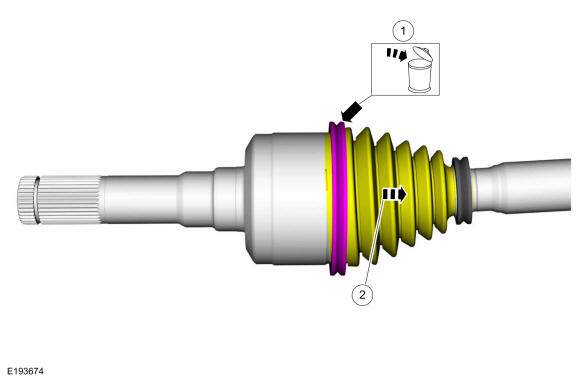
Remove and discard the large CV boot clamp.
-
Position the CV boot to access the inner CV housing retaining ring.
-
Remove and discard the large CV boot clamp.
 |
-
Remove and discard the inner CV housing retaining ring.
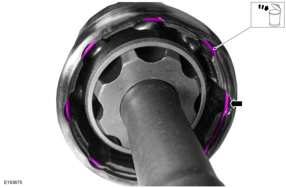 |
-
Remove the inner CV joint housing.
 |
-
NOTE: The CV joint cage balls are free to fall out.
Remove and discard the CV joint cage circlip.
 |
-
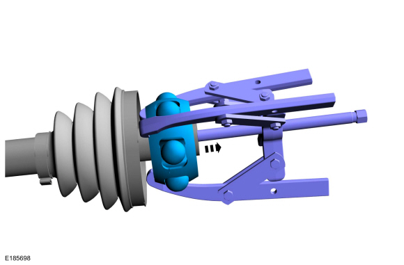
NOTE: The CV joint cage balls are free to fall out.
Using general equipment, remove the CV joint cage.
Use the General Equipment: Three Leg Puller
 |
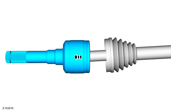
-
Remove and discard the small clamp and remove the CV joint boot.
 |
Installation
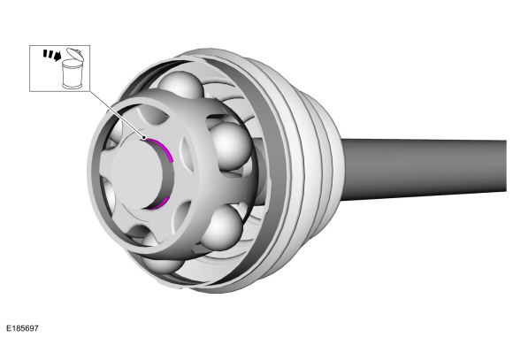
-
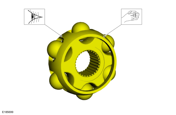
NOTE: CV cage is shown assembled.
Clean and inspect the CV joint cage.
 |
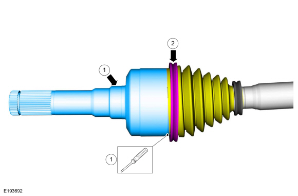
-
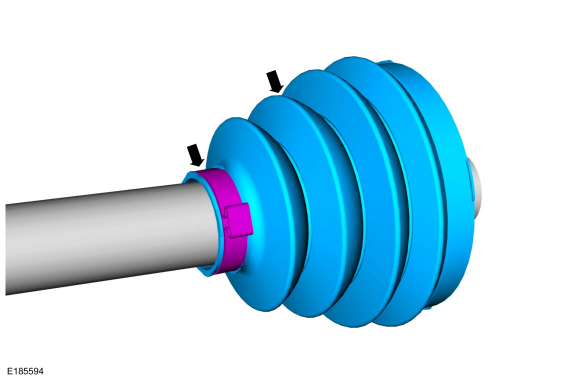
Using boot clamp pliers, install the new CV joint boot and the new small CV joint boot clamp.
Use the General Equipment: Boot Clamp Pliers
 |
-
NOTE: The CV joint cage is a snug fit and may need to tapped on with a soft face mallet.
Using a soft face mallet, install the CV joint cage.
Use the General Equipment: Rubber Mallet
 |
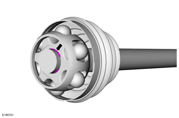
-
Install the new CV joint cage circlip.
 |
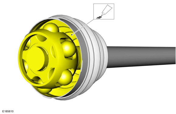
-
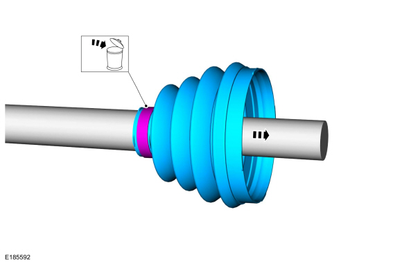
Install the grease sachet evenly in the CV joint boot and housing.
Material: Motorcraft® Constant Velocity Joint Grease / XG-5 (WSS-M1C258-A1)
 |
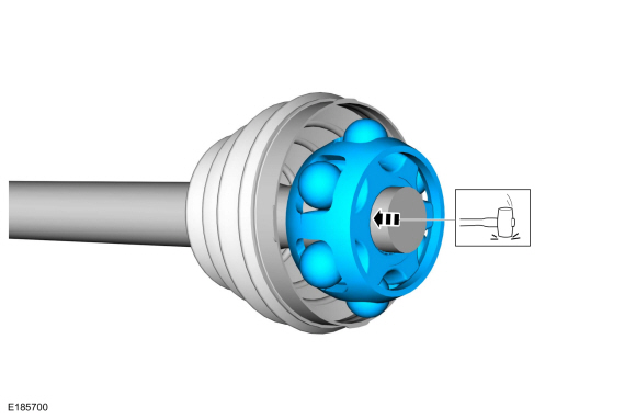
-
NOTE: When installing the CV joint housing, insert a small flat blade screwdriver under the CV joint boot seat to allow air to escape.
Install the inner CV housing and the new inner CV housing retaining ring.
-
Using a flat blade screw driver to allow air to escape, install the CV joint housing.
Use the General Equipment: Flat Headed Screw Driver
-
Using boot clamp pliers, install the new large CV joint boot clamp.
Use the General Equipment: Boot Clamp Pliers
-
Using a flat blade screw driver to allow air to escape, install the CV joint housing.
 |
-
Install the halfshaft.
Refer to: Halfshaft (205-04 Front Drive Halfshafts, Removal and Installation).
 Halfshaft. Removal and Installation
Special Tool(s) /
General Equipment
204-592Separator, Lower Arm Ball JointTKIT-2006C-FFMFLMTKIT-2006C-LMTKIT-2006C-ROW
Tie Rod End Remover
Tire Lever
Removal
NOTICE:
Suspension fasteners are critical parts that affect the
performance of vital components and systems...
 Outer Constant Velocity (CV) Joint Boot. Removal and Installation
Special Tool(s) /
General Equipment
Flat Headed Screw Driver
Boot Clamp Pliers
Removal
Remove the inner CV joint boot...
Other information:
Lincoln Navigator 2018-2026 Workshop Manual: Charge Air Cooler (CAC) Outlet Pipe. Removal and Installation
Removal NOTICE: The turbocharger compressor vanes can be damaged by even the smallest particles. When removing any turbocharger or engine air intake system component, ensure that no debris enters the system. Failure to do so may result in damage to the turbocharger...
Lincoln Navigator 2018-2026 Workshop Manual: Diagnosis By Symptom. Diagnosis and Testing
Global Customer Symptom Code (GCSC) Chart Diagnostics in this manual assume a certain skill level and knowledge of Ford-specific diagnostic practices REFER to: Diagnostic Methods (100-00 General Information, Description and Operation). Symptom Action Start/Run/Move > Moving > Shift Lever (Manual) > Sticks/Binds GO to Pinpoint Test N Start/Run/Move &g..
Categories
- Manuals Home
- 4th Gen Lincoln Navigator Service Manual (2018 - 2026)
- Identification Codes. Description and Operation
- SYNC Module [APIM]. Removal and Installation
- Rear View Mirrors - System Operation and Component Description. Description and Operation
- Windshield Washer Pump. Removal and Installation
- Neutral Flat Tow Activation and Deactivation. General Procedures
Axle Tube Bearing. Removal and Installation
Special Tool(s) / General Equipment
 205-123
(T78P-1177-A)
205-123
(T78P-1177-A)
Installer, Axle Shaft Oil Seal
 308-047
(T77F-1102-A)
308-047
(T77F-1102-A)
Remover, Bearing Cup Slide Hammer