Lincoln Navigator: Front Drive Halfshafts / Halfshaft. Removal and Installation
Special Tool(s) / General Equipment
 |
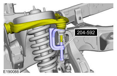
204-592 Separator, Lower Arm Ball Joint TKIT-2006C-FFMFLM TKIT-2006C-LM TKIT-2006C-ROW |
| Tie Rod End Remover | |
| Tire Lever | |
Removal
NOTICE: Suspension fasteners are critical parts that affect the performance of vital components and systems. Failure of these fasteners may result in major service expense. Use the same or equivalent parts if replacement is necessary. Do not use a replacement part of lesser quality or substitute design. Tighten fasteners as specified.
-
NOTE: If equipped.
Position vehicle on hoist.
Refer to: Jacking and Lifting (100-02 Jacking and Lifting, Description and Operation).
-
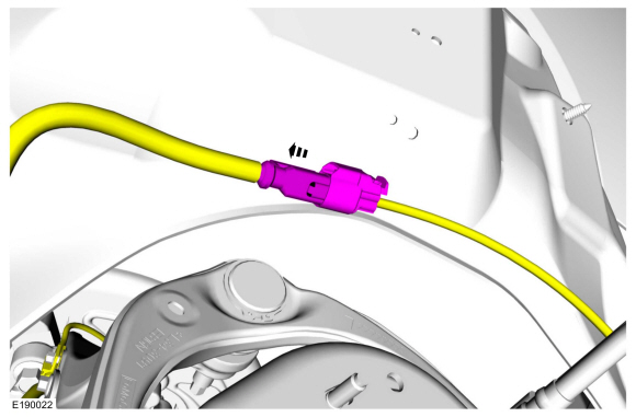
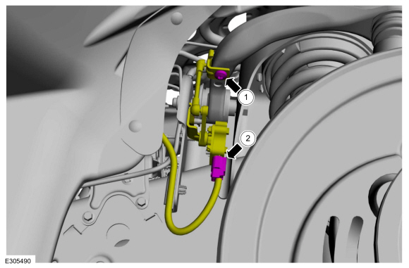
Disconnect the wheel speed sensor harness and position the harness aside.
 |
-
NOTE: If equipped.
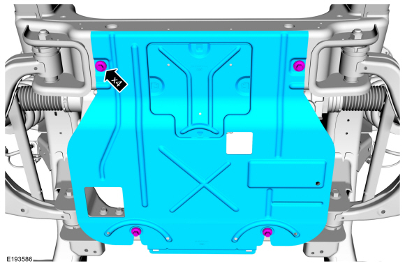
Remove the underbody shield bolts and remove the underbody shield.
Torque: 30 lb.ft (40 Nm)
 |
-
NOTE: If equipped.
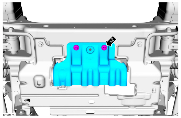
Remove the bolts, and remove the underbody shield.
Torque: 71 lb.in (8 Nm)
 |
-
NOTE: If equipped.
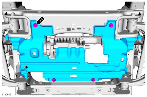
Remove the underbody shield bolts and remove the underbody shield.
Torque: 30 lb.ft (40 Nm)
 |
-
NOTE: Removal steps may contain installation details.
Remove the brake disc.
Refer to: Brake Disc (206-03 Front Disc Brake, Removal and Installation).
-
-
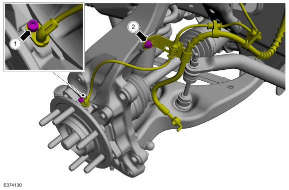
Remove the height sensor arm bracket screw.
Torque: 177 lb.in (20 Nm)
-
Disconnect the height sensor connector and keep aside the height sensor arm bracket.
-
Remove the height sensor arm bracket screw.
 |
-
-
Remove the wheel speed sensor wire bracket bolt.
Torque: 106 lb.in (12 Nm)
-
Remove the wheel speed sensor wire bracket bolt on
the wheel knuckle and position aside the wheel speed sensor wire.
Torque: 18 lb.ft (25 Nm)
-
Remove the wheel speed sensor wire bracket bolt.
 |
-
-
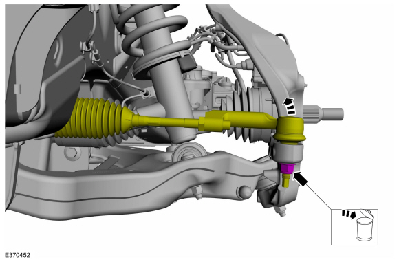
NOTE: Use the hex-holding feature to prevent the stud from turning while removing the nut.
Remove and discard the outer tie rod end nut.
Torque: 85 lb.ft (115 Nm)
-
NOTICE: Do not use a hammer to separate the outer tie-rod end from the wheel knuckle or damage to the wheel knuckle may result.
NOTICE: Use care when installing the tie rod separator or damage to the outer tie-rod end boot may occur.
Separate the outer tie rod end from the wheel knuckle.
Use the General Equipment: Tie Rod End Remover
-
 |
-
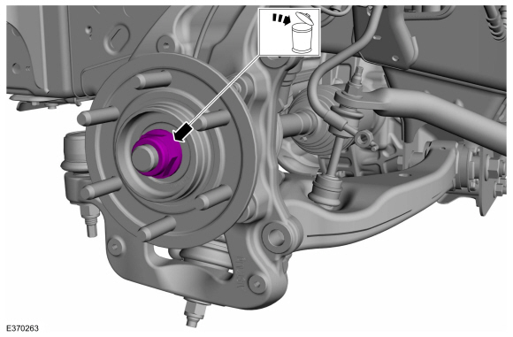
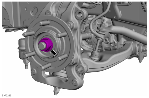
Remove and discard the wheel hub nut.
Torque: 184 lb.ft (250 Nm)
 |
-
NOTE: Use the hex-holding feature to prevent the stud from turning while removing the nut.
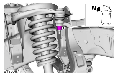
Remove and discard the upper ball joint nut.
Torque: 46 lb.ft (63 Nm)
 |
-
NOTE: Be sure not to damage the ball joint boot when installing the Ball Joint Separator.
Separate the upper ball joint from the wheel knuckle.
Use Special Service Tool: 204-592 Separator, Lower Arm Ball Joint.
 |
-
-
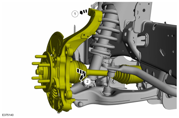
Position the wheel knuckle to gain access.
-
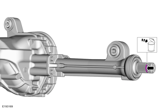
Remove the CV shaft joint outboard end.
-
Position the wheel knuckle to gain access.
 |
-
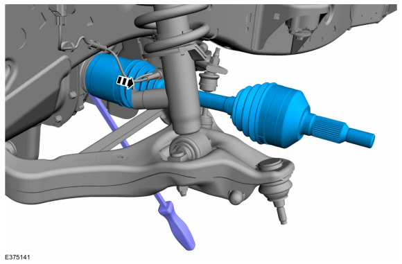
NOTE: Use care to not cause damage to the components.
Using the tire lever, remove the halfshaft from the differential and the intermediate shaft.
Use the General Equipment: Tire Lever
 |
-
Right-hand side.
-
Remove and discard the circlip.
-
Remove and discard the circlip.
 |
-
-
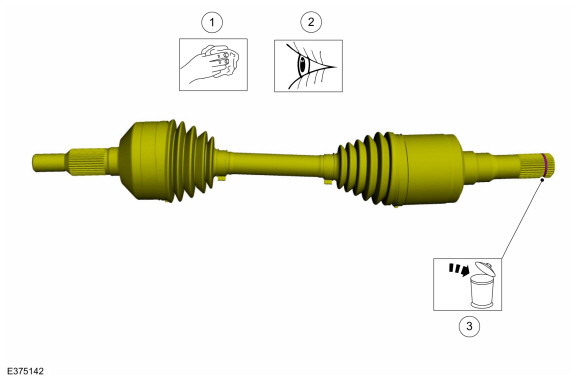
Clean the inner and outer halfshaft ends.
-
Inspect the inner and outer halfshaft ends.
-
Remove and discard the circlip.
-
Clean the inner and outer halfshaft ends.
 |
-
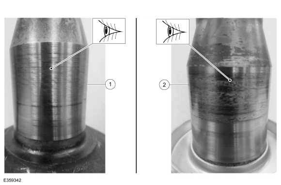
Inspect the inner CV housing.
-
Normal or acceptable wear.
-
Abnormal or excessive wear.
-
Normal or acceptable wear.
 |
Installation
-
If the LH halfshaft is removed, replace the LH axle shaft seal.
Refer to: Axle Shaft Seal (205-03 Front Drive Axle/Differential, Removal and Installation).
-
To install, reverse the removal procedure.
-
NOTICE: Verify the spline engagement by checking for spline lash before installing the wheel hub nut or component damage may occur.
-
Install the new the axle nut.
Torque: 184 lb.ft (250 Nm)
-
Verify free rotation of the hub with no CV joint rotation. No clicking or grinding noise should be present.
-
Install the new the axle nut.
 |
-
Check the front differential fluid level.
Refer to: Differential Fluid Level Check (205-03 Front Drive Axle/Differential, General Procedures).
- If equipped with dynamic suspension, calibrate the suspension height sensor. Connect the scan tool and carry out the Ride Height Calibration routine. Follow the scan tool directions.
 Front Drive Halfshafts. Diagnosis and Testing
Preliminary Inspection
Visually inspect the CV joints, housing, boots, and clamps for obvious signs of mechanical damage.
If an obvious cause for an observed or reported concern is
found, correct the cause (if possible) before proceeding to the next
step
If the cause is not visually evident, verify the symptom and REFER to Symptom Chart: NVH...
 Inner Constant Velocity (CV) Joint Boot. Removal and Installation
Special Tool(s) /
General Equipment
Flat Headed Screw Driver
Boot Clamp Pliers
Rubber Mallet
Three Leg Puller
Materials
Name
Specification
Motorcraft® Constant Velocity Joint GreaseXG-5
WSS-M1C258-A1
Removal
Remove the halfshaft...
Other information:
Lincoln Navigator 2018-2026 Workshop Manual: Third Row Double Seat Center Seatbelt Buckle. Removal and Installation
Removal NOTE: Removal steps in this procedure may contain installation details. Remove the third row double seat. Refer to: Third Row Seat (501-10C Third Row Seats, Removal and Installation). Remove the third row double seat center seatbelt buckle...
Lincoln Navigator 2018-2026 Workshop Manual: Front Door Window Glass. Removal and Installation
Removal NOTE: LH side shown, RH side similar. Remove the front door glass top run. Refer to: Front Door Glass Top Run (501-11 Glass, Frames and Mechanisms, Removal and Installation). Remove the front door glass...
Categories
- Manuals Home
- 4th Gen Lincoln Navigator Service Manual (2018 - 2026)
- Front Bumper Cover. Removal and Installation
- Transmission Fluid Level Check. General Procedures
- Body Control Module (BCM). Removal and Installation
- All Terrain Control Module (ATCM). Removal and Installation
- Power Running Board (PRB). Diagnosis and Testing
Differential Case Runout Check. General Procedures
Special Tool(s) / General Equipment
 205-1016
Installer, Differential Bearing
TKIT-2014D-ROW2
TKIT-2014D-FL_ROW
 205-153
(T80T-4000-W)
205-153
(T80T-4000-W)
Handle
 205-D061
(D83T-4205-C2)
205-D061
(D83T-4205-C2)
Step Plate Dial Indicator Three Leg Puller Punch