Lincoln Navigator: Fuel Charging and Controls - 3.5L EcoBoost (272kW/370PS) / Fuel Pump Driver Module (FPDM). Removal and Installation
Removal
NOTE: The fuel pump driver module may be in either of two locations.
NOTE: The top-frame-mounted fuel pump driver module is on top of the left frame rail, behind the left rear wheel.
NOTE: The side-frame-mounted fuel pump driver module is on the outside of the left frame rail, under the driver’s door.
All Vehicles
-
For component location see.
Refer to: Fuel Charging and Controls - Component Location (303-04A Fuel Charging and Controls - 3.5L EcoBoost (272kW/370PS), Description and Operation).
-
With the vehicle in NEUTRAL, position it on a hoist.
Refer to: Jacking and Lifting (100-02 Jacking and Lifting, Description and Operation).
Top Frame Mounted Fuel Pump Driver Module
-
Remove the left rear splash shield retainer, then position the left rear splash shield out of the way.
 |
-
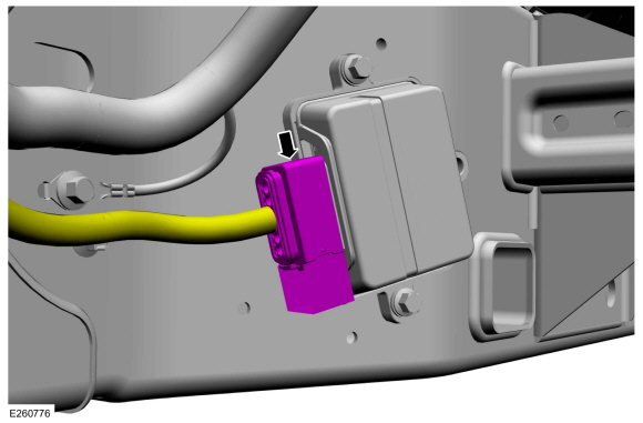
Disconnect the fuel pump driver module electrical connector.
 |
-
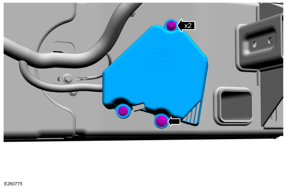
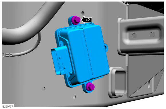
Remove the fuel pump driver module bolts, then remove the fuel pump driver module.
 |
Side Frame Mounted Fuel Pump Driver Module
-
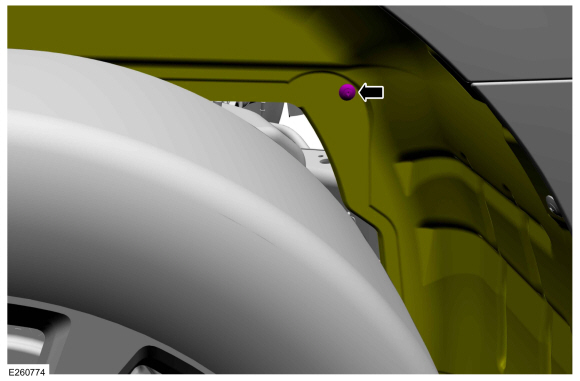
Remove the fuel pump driver module cover retainers, then remove the fuel pump driver module cover.
 |
-
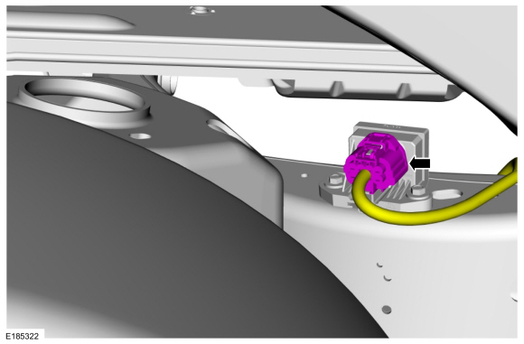
Disconnect the fuel pump driver module electrical connector.
 |
-
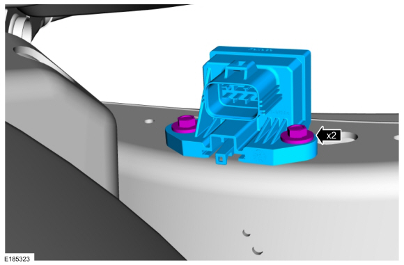
Remove the fuel pump driver module bolts, then remove the fuel pump driver module.
 |
Installation
Side Frame Mounted Fuel Pump Driver Module
-
Install the fuel pump driver module, then install and tighten the fuel pump driver module bolts.
Torque: 133 lb.in (15 Nm)
|
-
Connect the fuel pump driver module electrical connector.
|
-
Install the fuel pump driver module cover, then
install and tighten the fuel pump driver module cover retainers.
Torque: 133 lb.in (15 Nm)
|
Top Frame Mounted Fuel Pump Driver Module
-
Install the fuel pump driver module, then install and tighten the fuel pump driver module bolts.
Torque: 133 lb.in (15 Nm)
|
-
Connect the fuel pump driver module electrical connector.
|
-
Install the left rear splash shield, then install the left rear splash shield retainer.
|
 Fuel Injectors. Removal and Installation
Removal and Installation
The fuel injectors are removed with the fuel rails.
Refer to: Direct Injection Fuel Rail LH (303-04A Fuel Charging and
Controls - 3...
 High-Pressure Fuel Pump. Removal and Installation
Removal
NOTICE:
Do not loosen any fittings or plugs on the high-pressure fuel pump.
With the vehicle in NEUTRAL, position it on a hoist...
Other information:
Lincoln Navigator 2018-2026 Workshop Manual: Headlamp Adjustment. General Procedures
Adjustment NOTE: If the flash video link does not load or is incompatible with your browser, a .wmv version of the video can be accessed at: http://www.fordservicecontent.com/Ford_Content/videos/FusionHeadlampAdj2.wmv Click on the link above to view video...
Lincoln Navigator 2018-2026 Workshop Manual: AM/FM1 Antenna Amplifier. Removal and Installation
Removal NOTE: Removal steps in this procedure may contain installation details. Remove the upper RH C-pillar trim panel. Refer to: C-Pillar Trim Panel (501-05 Interior Trim and Ornamentation, Removal and Installation). Disconnect the electrical connectors, remove the bolt and the AM / FM amplifier...
Categories
- Manuals Home
- 4th Gen Lincoln Navigator Service Manual (2018 - 2026)
- Rear View Mirrors - System Operation and Component Description. Description and Operation
- Telematics Control Unit (TCU) Module. Removal and Installation
- Brake Service Mode Activation and Deactivation. General Procedures
- SYNC Module [APIM]. Removal and Installation
- Windshield Washer Pump. Removal and Installation
Rear Stabilizer Bar Link. Removal and Installation
Removal
NOTE: Removal steps in this procedure may contain installation details.
With the vehicle in NEUTRAL, position it on a hoist.Refer to: Jacking and Lifting (100-02 Jacking and Lifting, Description and Operation).
NOTE: Use the hex-holding feature to prevent the stud from turning while removing the nut.
Remove and discard the 2 rear stabilizer bar link nuts and remove the rear stabilizer bar link.Torque: 46 lb.ft (63 Nm)
