Lincoln Navigator: Front Seats / Front Seats. Diagnosis and Testing
DTC Chart: DDM
Diagnostics in this manual assume a certain skill level and knowledge of Ford-specific diagnostic practices.
REFER to: Diagnostic Methods (100-00 General Information, Description and Operation).
DDM DTC Chart
| DTC | Description | Action |
|---|---|---|
| B1C03:23 | Memory #1 Switch: Signal Stuck Low | GO to Pinpoint Test K |
| B1C04:23 | Memory #2 Switch: Signal Stuck Low | GO to Pinpoint Test K |
| B1C05:23 | Memory #3 Switch: Signal Stuck Low | GO to Pinpoint Test K |
| All other Diagnostic Trouble Codes (DTCs) | - |
REFER to: Locks, Latches and Entry Systems (501-14 Handles, Locks, Latches and Entry Systems, Diagnosis and Testing). |
DTC Chart: PDM
Diagnostics in this manual assume a certain skill level and knowledge of Ford-specific diagnostic practices.
REFER to: Diagnostic Methods (100-00 General Information, Description and Operation).
PDM DTC Chart
| DTC | Description | Action |
|---|---|---|
| B1C03:23 | Memory #1 Switch: Signal Stuck Low | GO to Pinpoint Test C |
| B1C04:23 | Memory #2 Switch: Signal Stuck Low | GO to Pinpoint Test C |
| B1C05:23 | Memory #3 Switch: Signal Stuck Low | GO to Pinpoint Test C |
| All other Diagnostic Trouble Codes (DTCs) | - |
REFER to: Locks, Latches and Entry Systems (501-14 Handles, Locks, Latches and Entry Systems, Diagnosis and Testing). |
DTC Chart: DSM
Diagnostics in this manual assume a certain skill level and knowledge of Ford-specific diagnostic practices.
REFER to: Diagnostic Methods (100-00 General Information, Description and Operation).
DSM DTC Chart
| DTC | Description | Action |
|---|---|---|
| B1029:11 | Accelerator Pedal Sensor: Circuit Short To Ground |
REFER to: Hydraulic Brake Actuation (206-06 Hydraulic Brake Actuation, Diagnosis and Testing). |
| B1029:15 | Accelerator Pedal Sensor: Circuit Short To Battery or Open |
REFER to: Hydraulic Brake Actuation (206-06 Hydraulic Brake Actuation, Diagnosis and Testing). |
| B1060:11 | Seat Headrest Motor Output: Circuit Short To Ground | GO to Pinpoint Test O |
| B1060:12 | Seat Headrest Motor Output: Circuit Short To Battery | GO to Pinpoint Test O |
| B1060:13 | Seat Headrest Motor Output: Circuit Open | GO to Pinpoint Test O |
| B1067:24 | Lumbar In Switch: Signal Stuck High | GO to Pinpoint Test AC |
| B1068:24 | Lumbar Out Switch: Signal Stuck High | GO to Pinpoint Test AC |
| B106D:24 | Headrest Up Switch: Signal Stuck High | GO to Pinpoint Test AC |
| B106E:24 | Headrest Down Switch: Signal Stuck High | GO to Pinpoint Test AC |
| B1087:83 | LIN Bus "A": Value of Signal Protection Calculation Incorrect | GO to Pinpoint Test AA |
| B1087:87 | LIN Bus "A": Missing Message | GO to Pinpoint Test AA |
| B11D1:83 | LIN Bus "C": Value of Signal Protection Calculation Incorrect | GO to Pinpoint Test O |
| B11D1:87 | LIN Bus "C": Missing Message | GO to Pinpoint Test O |
| B1298:24 | Steering Column Adjust Up Switch: Signal Stuck High |
REFER to: Steering Column (211-04 Steering Column, Diagnosis and Testing). |
| B1299:24 | Steering Column Adjust Down Switch: Signal Stuck High |
REFER to: Steering Column (211-04 Steering Column, Diagnosis and Testing). |
| B12A1:24 | Steering Column Adjust Out Switch: Signal Stuck High |
REFER to: Steering Column (211-04 Steering Column, Diagnosis and Testing). |
| B12A2:24 | Steering Column Adjust In Switch: Signal Stuck High |
REFER to: Steering Column (211-04 Steering Column, Diagnosis and Testing). |
| B12A7:11 | Steering Column Tilt Sensor A: Circuit Short To Ground |
REFER to: Steering Column (211-04 Steering Column, Diagnosis and Testing). |
| B12A7:15 | Steering Column Tilt Sensor A: Circuit Short To Battery or Open |
REFER to: Steering Column (211-04 Steering Column, Diagnosis and Testing). |
| B12A8:11 | Steering Column Telescope Sensor A: Circuit Short To Ground |
REFER to: Steering Column (211-04 Steering Column, Diagnosis and Testing). |
| B12A8:15 | Steering Column Telescope Sensor A: Circuit Short To Battery or Open |
REFER to: Steering Column (211-04 Steering Column, Diagnosis and Testing). |
| B1375:11 | Steering Column Tilt Motor: Circuit Short To Ground |
REFER to: Steering Column (211-04 Steering Column, Diagnosis and Testing). |
| B1375:12 | Steering Column Tilt Motor: Circuit Short To Battery |
REFER to: Steering Column (211-04 Steering Column, Diagnosis and Testing). |
| B1375:13 | Steering Column Tilt Motor: Circuit Open |
REFER to: Steering Column (211-04 Steering Column, Diagnosis and Testing). |
| B137D:11 | Pedal Adjustment Motor: Circuit Short To Ground |
REFER to: Hydraulic Brake Actuation (206-06 Hydraulic Brake Actuation, Diagnosis and Testing). |
| B137D:12 | Pedal Adjustment Motor: Circuit Short To Battery |
REFER to: Hydraulic Brake Actuation (206-06 Hydraulic Brake Actuation, Diagnosis and Testing). |
| B137D:13 | Pedal Adjustment Motor: Circuit Open |
REFER to: Hydraulic Brake Actuation (206-06 Hydraulic Brake Actuation, Diagnosis and Testing). |
| B137E:11 | Steering Column Telescope Motor: Circuit Short To Ground |
REFER to: Steering Column (211-04 Steering Column, Diagnosis and Testing). |
| B137E:12 | Steering Column Telescope Motor: Circuit Short To Battery |
REFER to: Steering Column (211-04 Steering Column, Diagnosis and Testing). |
| B137E:13 | Steering Column Telescope Motor: Circuit Open |
REFER to: Steering Column (211-04 Steering Column, Diagnosis and Testing). |
| B14C3:24 | Seat Height Rear Down Switch: Signal Stuck High | GO to Pinpoint Test AC |
| B14C4:24 | Seat Height Rear Up Switch: Signal Stuck High | GO to Pinpoint Test AC |
| B14C5:24 | Seat Headrest Forward Switch: Signal Stuck High | GO to Pinpoint Test AC |
| B14C6:24 | Seat Headrest Rearward Switch: Signal Stuck High | GO to Pinpoint Test AC |
| B14C7:24 | Adjustable Pedal Forward Switch: Signal Stuck High |
REFER to: Hydraulic Brake Actuation (206-06 Hydraulic Brake Actuation, Diagnosis and Testing). |
| B14C8:24 | Adjustable Pedal Rearward Switch: Signal Stuck High |
REFER to: Hydraulic Brake Actuation (206-06 Hydraulic Brake Actuation, Diagnosis and Testing). |
| B14CE:11 | Seat Horizontal Motor Output: Circuit Short To Ground | GO to Pinpoint Test I |
| B14CE:12 | Seat Horizontal Motor Output: Circuit Short To Battery | GO to Pinpoint Test I |
| B14CE:13 | Seat Horizontal Motor Output: Circuit Open | GO to Pinpoint Test I |
| B14CF:11 | Seat Recline Motor Output: Circuit Short To Ground | GO to Pinpoint Test I |
| B14CF:12 | Seat Recline Motor Output: Circuit Short To Battery | GO to Pinpoint Test I |
| B14CF:13 | Seat Recline Motor Output: Circuit Open | GO to Pinpoint Test I |
| B14D0:11 | Seat Height Front/Tilt Motor Output: Circuit Short To Ground | GO to Pinpoint Test I |
| B14D0:12 | Seat Height Front/Tilt Motor Output: Circuit Short To Battery | GO to Pinpoint Test I |
| B14D0:13 | Seat Height Front/Tilt Motor Output: Circuit Open | GO to Pinpoint Test I |
| B14D2:11 | Seat Height Rear Motor Output: Circuit Short To Ground | GO to Pinpoint Test I |
| B14D2:12 | Seat Height Rear Motor Output: Circuit Short To Battery | GO to Pinpoint Test I |
| B14D2:13 | Seat Height Rear Motor Output: Circuit Open | GO to Pinpoint Test I |
| B151F:11 | Left Cushion Motor Output: Circuit Short To Ground | GO to Pinpoint Test N |
| B151F:12 | Left Cushion Motor Output: Circuit Short To Battery | GO to Pinpoint Test N |
| B151F:13 | Left Cushion Motor Output: Circuit Open | GO to Pinpoint Test N |
| B1520:11 | Right Cushion Motor Output: Circuit Short To Ground | GO to Pinpoint Test N |
| B1520:12 | Right Cushion Motor Output: Circuit Short To Battery | GO to Pinpoint Test N |
| B1520:13 | Right Cushion Motor Output: Circuit Open | GO to Pinpoint Test N |
| B1521:11 | Upper Back Pivot Motor Output: Circuit Short To Ground | GO to Pinpoint Test M |
| B1521:12 | Upper Back Pivot Motor Output: Circuit Short To Battery | GO to Pinpoint Test M |
| B1521:13 | Upper Back Pivot Motor Output: Circuit Open | GO to Pinpoint Test M |
| B1522:11 | Lumbar Motor Output: Circuit Short To Ground | GO to Pinpoint Test J |
| B1522:12 | Lumbar Motor Output: Circuit Short To Battery | GO to Pinpoint Test J |
| B1522:13 | Lumbar Motor Output: Circuit Open | GO to Pinpoint Test J |
| B1527:24 | Left Cushion Fore Switch: Signal Stuck High | GO to Pinpoint Test AC |
| B1528:24 | Left Cushion Aft Switch: Signal Stuck High | GO to Pinpoint Test AC |
| B1529:24 | Right Cushion Fore Switch: Signal Stuck High | GO to Pinpoint Test AC |
| B152A:24 | Right Cushion Aft Switch: Signal Stuck High | GO to Pinpoint Test AC |
| B152B:24 | Upper Back Pivot Fore Switch: Signal Stuck High | GO to Pinpoint Test AC |
| B152C:24 | Upper Back Pivot Aft Switch: Signal Stuck High | GO to Pinpoint Test AC |
| B1679:96 | Headrest: Component Internal Failure | GO to Pinpoint Test O |
| B1B96:24 | Seat Slide Forward Switch: Signal Stuck High | GO to Pinpoint Test AC |
| B1B97:24 | Seat Slide Backward Switch: Signal Stuck High | GO to Pinpoint Test AC |
| B1B98:24 | Seat Tilt Up Switch: Signal Stuck High | GO to Pinpoint Test AC |
| B1B99:24 | Seat Tilt Down Switch: Signal Stuck High | GO to Pinpoint Test AC |
| B1C00:24 | Seat Recline Up Switch: Signal Stuck High | GO to Pinpoint Test AC |
| B1C01:24 | Seat Recline Down Switch: Signal Stuck High | GO to Pinpoint Test AC |
| U0100:00 | Lost Communication with ECM/PCM "A": No Sub Type Information | GO to Pinpoint Test R |
| U0140:00 | Lost Communication with Body Control Module: No Sub Type Information | GO to Pinpoint Test S |
| U0199:00 | Lost Communication With "Door Control Module A": No Sub Type Information | GO to Pinpoint Test T |
| U0212:00 | Lost Communication with Steering Column Control Module: No Sub Type Information | GO to Pinpoint Test V |
| U0253:00 | Lost Communication With Accessory Protocol Interface Module: No Sub Type Information | GO to Pinpoint Test W |
| U2013:24 | Switch Pack: Signal Stuck High | GO to Pinpoint Test AC |
| U2100:00 | Initial Configuration Not Complete: No Sub Type Information | GO to Pinpoint Test X |
| U3000:49 | Control Module: Internal Electronic Failure | GO to Pinpoint Test Y |
| U3500:17 | Control Module Input Power "A" Circuit Range/Performance: Circuit Voltage Above Threshold | GO to Pinpoint Test Z |
DTC Chart: SCMB
Diagnostics in this manual assume a certain skill level and knowledge of Ford-specific diagnostic practices.
REFER to: Diagnostic Methods (100-00 General Information, Description and Operation).
SCMB DTC Chart
| DTC | Description | Action |
|---|---|---|
| B1060:11 | Seat Headrest Motor Output: Circuit Short To Ground | GO to Pinpoint Test G |
| B1060:12 | Seat Headrest Motor Output: Circuit Short To Battery | GO to Pinpoint Test G |
| B1060:13 | Seat Headrest Motor Output: Circuit Open | GO to Pinpoint Test G |
| B1067:24 | Lumbar In Switch: Signal Stuck High | GO to Pinpoint Test AD |
| B1068:24 | Lumbar Out Switch: Signal Stuck High | GO to Pinpoint Test AD |
| B106D:24 | Headrest Up Switch: Signal Stuck High | GO to Pinpoint Test AD |
| B106E:24 | Headrest Down Switch: Signal Stuck High | GO to Pinpoint Test AD |
| B1087:83 | LIN Bus "A": Value of Signal Protection Calculation Incorrect | GO to Pinpoint Test AB |
| B1087:87 | LIN Bus "A": Missing Message | GO to Pinpoint Test AB |
| B11D1:83 | LIN Bus "C": Value of Signal Protection Calculation Incorrect | GO to Pinpoint Test G |
| B11D1:87 | LIN Bus "C": Missing Message | GO to Pinpoint Test G |
| B14C3:24 | Seat Height Rear Down Switch: Signal Stuck High | GO to Pinpoint Test AD |
| B14C4:24 | Seat Height Rear Up Switch: Signal Stuck High | GO to Pinpoint Test AD |
| B14C5:24 | Seat Headrest Forward Switch: Signal Stuck High | GO to Pinpoint Test AD |
| B14C6:24 | Seat Headrest Rearward Switch: Signal Stuck High | GO to Pinpoint Test AD |
| B14CE:11 | Seat Horizontal Motor Output: Circuit Short To Ground | GO to Pinpoint Test A |
| B14CE:12 | Seat Horizontal Motor Output: Circuit Short To Battery | GO to Pinpoint Test A |
| B14CE:13 | Seat Horizontal Motor Output: Circuit Open | GO to Pinpoint Test A |
| B14CF:11 | Seat Recline Motor Output: Circuit Short To Ground | GO to Pinpoint Test A |
| B14CF:12 | Seat Recline Motor Output: Circuit Short To Battery | GO to Pinpoint Test A |
| B14CF:13 | Seat Recline Motor Output: Circuit Open | GO to Pinpoint Test A |
| B14D0:11 | Seat Height Front/Tilt Motor Output: Circuit Short To Ground | GO to Pinpoint Test A |
| B14D0:12 | Seat Height Front/Tilt Motor Output: Circuit Short To Battery | GO to Pinpoint Test A |
| B14D0:13 | Seat Height Front/Tilt Motor Output: Circuit Open | GO to Pinpoint Test A |
| B14D2:11 | Seat Height Rear Motor Output: Circuit Short To Ground | GO to Pinpoint Test A |
| B14D2:12 | Seat Height Rear Motor Output: Circuit Short To Battery | GO to Pinpoint Test A |
| B14D2:13 | Seat Height Rear Motor Output: Circuit Open | GO to Pinpoint Test A |
| B151F:11 | Left Cushion Motor Output: Circuit Short To Ground | GO to Pinpoint Test F |
| B151F:12 | Left Cushion Motor Output: Circuit Short To Battery | GO to Pinpoint Test F |
| B151F:13 | Left Cushion Motor Output: Circuit Open | GO to Pinpoint Test F |
| B1520:11 | Right Cushion Motor Output: Circuit Short To Ground | GO to Pinpoint Test F |
| B1520:12 | Right Cushion Motor Output: Circuit Short To Battery | GO to Pinpoint Test F |
| B1520:13 | Right Cushion Motor Output: Circuit Open | GO to Pinpoint Test F |
| B1521:11 | Upper Back Pivot Motor Output: Circuit Short To Ground | GO to Pinpoint Test E |
| B1521:12 | Upper Back Pivot Motor Output: Circuit Short To Battery | GO to Pinpoint Test E |
| B1521:13 | Upper Back Pivot Motor Output: Circuit Open | GO to Pinpoint Test E |
| B1522:11 | Lumbar Motor Output: Circuit Short To Ground | GO to Pinpoint Test B |
| B1522:12 | Lumbar Motor Output: Circuit Short To Battery | GO to Pinpoint Test B |
| B1522:13 | Lumbar Motor Output: Circuit Open | GO to Pinpoint Test B |
| B1527:24 | Left Cushion Fore Switch: Signal Stuck High | GO to Pinpoint Test AD |
| B1528:24 | Left Cushion Aft Switch: Signal Stuck High | GO to Pinpoint Test AD |
| B1529:24 | Right Cushion Fore Switch: Signal Stuck High | GO to Pinpoint Test AD |
| B152A:24 | Right Cushion Aft Switch: Signal Stuck High | GO to Pinpoint Test AD |
| B152B:24 | Upper Back Pivot Fore Switch: Signal Stuck High | GO to Pinpoint Test AD |
| B152C:24 | Upper Back Pivot Aft Switch: Signal Stuck High | GO to Pinpoint Test AD |
| B1679:96 | Headrest: Component Internal Failure | GO to Pinpoint Test G |
| B1B96:24 | Seat Slide Forward Switch: Signal Stuck High | GO to Pinpoint Test AD |
| B1B97:24 | Seat Slide Backward Switch: Signal Stuck High | GO to Pinpoint Test AD |
| B1B98:24 | Seat Tilt Up Switch: Signal Stuck High | GO to Pinpoint Test AD |
| B1B99:24 | Seat Tilt Down Switch: Signal Stuck High | GO to Pinpoint Test AD |
| B1C00:24 | Seat Recline Up Switch: Signal Stuck High | GO to Pinpoint Test AD |
| B1C01:24 | Seat Recline Down Switch: Signal Stuck High | GO to Pinpoint Test AD |
| U0100:00 | Lost Communication with ECM/PCM "A": No Sub Type Information | GO to Pinpoint Test R |
| U0140:00 | Lost Communication with Body Control Module: No Sub Type Information | GO to Pinpoint Test S |
| U0199:00 | Lost Communication With "Door Control Module A": No Sub Type Information | GO to Pinpoint Test U |
| U0253:00 | Lost Communication With Accessory Protocol Interface Module: No Sub Type Information | GO to Pinpoint Test W |
| U2013:24 | Switch Pack: Signal Stuck High | GO to Pinpoint Test AD |
| U2100:00 | Initial Configuration Not Complete: No Sub Type Information | GO to Pinpoint Test X |
| U3000:49 | Control Module: Internal Electronic Failure | GO to Pinpoint Test Y |
| U3500:17 | Control Module Input Power "A" Circuit Range/Performance: Circuit Voltage Above Threshold | GO to Pinpoint Test Z |
DTC Chart: SCME
Diagnostics in this manual assume a certain skill level and knowledge of Ford-specific diagnostic practices.
REFER to: Diagnostic Methods (100-00 General Information, Description and Operation).
SCME DTC Chart
| DTC | Description | Action |
|---|---|---|
| B1153:4B | Driver Seat Cushion: Over Temperature | GO to Pinpoint Test AE |
| B1208:01 | Driver Seat Cushion Temperature Sensor: General Electrical Failure | GO to Pinpoint Test AE |
| B1208:11 | Driver Seat Cushion Temperature Sensor: Circuit Short To Ground | GO to Pinpoint Test AE |
| B1208:15 | Driver Seat Cushion Temperature Sensor: Circuit Short To Battery or Open | GO to Pinpoint Test AE |
| B1208:2A | Driver Seat Cushion Temperature Sensor: Signal Stuck In Range | GO to Pinpoint Test AE |
| B14B9:11 | Driver Seat Cushion Thermal Electric Device: Circuit Short To Ground | GO to Pinpoint Test AE |
| B14B9:12 | Driver Seat Cushion Thermal Electric Device: Circuit Short To Battery | GO to Pinpoint Test AE |
| B14B9:13 | Driver Seat Cushion Thermal Electric Device: Circuit Open | GO to Pinpoint Test AE |
| B14BD:11 | Driver Seat Cushion Blower: Circuit Short To Ground | GO to Pinpoint Test AG |
| B14BD:13 | Driver Seat Cushion Blower: Circuit Open | GO to Pinpoint Test AG |
| B1562:11 | Driver Seat Back Blower Speed: Circuit Short To Ground | GO to Pinpoint Test AG |
| B1562:12 | Driver Seat Back Blower Speed: Circuit To Battery | GO to Pinpoint Test AG |
| B1564:11 | Driver Seat Cushion Blower Speed: Circuit Short To Ground | GO to Pinpoint Test AG |
| B1564:12 | Driver Seat Cushion Blower Speed: Circuit To Battery | GO to Pinpoint Test AG |
| U0140:00 | Lost Communication with Body Control Module: No Sub Type Information | GO to Pinpoint Test AI |
| U0257:00 | Lost Communication with Front Controls / Display Interface Module: No Sub Type Information | GO to Pinpoint Test AK |
| U1000:00 | Solid State Driver Protection Active -Driver Disabled: No Sub Type Information | GO to Pinpoint Test AM |
| U2100:00 | Initial Configuration Not Complete: No Sub Type Information | GO to Pinpoint Test AO |
| U3000:49 | Control Module: Internal Electronic Failure | GO to Pinpoint Test AQ |
DTC Chart: SCMF
Diagnostics in this manual assume a certain skill level and knowledge of Ford-specific diagnostic practices.
REFER to: Diagnostic Methods (100-00 General Information, Description and Operation).
SCMF DTC Chart
| DTC | Description | Action |
|---|---|---|
| B1151:4B | Passenger Seat Cushion: Over Temperature | GO to Pinpoint Test AF |
| B120A:11 | Passenger Seat Cushion Temperature Sensor: Circuit Short To Ground | GO to Pinpoint Test AF |
| B120A:15 | Passenger Seat Cushion Temperature Sensor: Circuit Short To Battery or Open | GO to Pinpoint Test AF |
| B120A:2A | Passenger Seat Cushion Temperature Sensor: Signal Stuck In Range | GO to Pinpoint Test AF |
| B14BB:11 | Passenger Seat Cushion Thermal Electric Device: Circuit Short To Ground | GO to Pinpoint Test AF |
| B14BB:12 | Passenger Seat Cushion Thermal Electric Device: Circuit Short To Battery | GO to Pinpoint Test AF |
| B14BB:13 | Passenger Seat Cushion Thermal Electric Device: Circuit Open | GO to Pinpoint Test AF |
| B14C0:11 | Passenger Seat Cushion Blower: Circuit Short To Ground | GO to Pinpoint Test AH |
| B14C0:13 | Passenger Seat Cushion Blower: Circuit Open | GO to Pinpoint Test AH |
| B1563:11 | Passenger Seat Back Blower Speed: Circuit Short To Ground | GO to Pinpoint Test AH |
| B1563:12 | Passenger Seat Back Blower Speed: Circuit Short To Battery | GO to Pinpoint Test AH |
| B1565:11 | Passenger Seat Cushion Blower Speed: Circuit Short To Ground | GO to Pinpoint Test AH |
| B1565:12 | Passenger Seat Cushion Blower Speed: Circuit Short To Battery | GO to Pinpoint Test AH |
| U0140:00 | Lost Communication with Body Control Module: No Sub Type Information | GO to Pinpoint Test AJ |
| U0257:00 | Lost Communication with Front Controls / Display Interface Module: No Sub Type Information | GO to Pinpoint Test AL |
| U1000:00 | Solid State Driver Protection Active -Driver Disabled: No Sub Type Information | GO to Pinpoint Test AN |
| U2100:00 | Initial Configuration Not Complete: No Sub Type Information | GO to Pinpoint Test AP |
| U3000:49 | Control Module: Internal Electronic Failure | GO to Pinpoint Test AR |
DTC Chart: SCMG
Diagnostics in this manual assume a certain skill level and knowledge of Ford-specific diagnostic practices.
REFER to: Diagnostic Methods (100-00 General Information, Description and Operation).
SCMG DTC Chart
| DTC | Description | Action |
|---|---|---|
| B146F:00 | Back Bladder System Electropneumatic Failure: No Sub Type Information | GO to Pinpoint Test AS |
| B146F:04 | Back Bladder System Electropneumatic Failure: System Internal Failure | GO to Pinpoint Test AS |
| B146F:87 | Back Bladder System Electropneumatic Failure: Missing Message | GO to Pinpoint Test AS |
| B1470:00 | Cushion Bladder System Electropneumatic Failure: No Sub Type Information | GO to Pinpoint Test AS |
| B1470:04 | Cushion Bladder System Electropneumatic Failure: System Internal Failure | GO to Pinpoint Test AS |
| B1470:87 | Cushion Bladder System Electropneumatic Failure: Missing Message | GO to Pinpoint Test AS |
| B1473:11 | Pump Driver: Circuit Short To Ground | GO to Pinpoint Test AS |
| U0140:00 | Lost Communication With Body Control Module: No Sub Type Information | GO to Pinpoint Test AU |
| U0208:00 | Lost Communication With "Seat Control Module A": No Sub Type Information | GO to Pinpoint Test AV |
| U0253:00 | Lost Communication With Accessory Protocol Interface Module: No Sub Type Information | GO to Pinpoint Test AX |
| U0256:00 | Lost Communication With Front Controls Interface Module "A": No Sub Type Information | GO to Pinpoint Test AY |
| U2100:00 | Initial Configuration Not Complete: No Sub Type Information | GO to Pinpoint Test BA |
| U3000:49 | Control Module: Internal Electronic Failure | GO to Pinpoint Test BB |
DTC Chart: SCMH
Diagnostics in this manual assume a certain skill level and knowledge of Ford-specific diagnostic practices.
REFER to: Diagnostic Methods (100-00 General Information, Description and Operation).
SCMH DTC Chart
| DTC | Description | Action |
|---|---|---|
| B146F:00 | Back Bladder System Electropneumatic Failure: No Sub Type Information | GO to Pinpoint Test AT |
| B146F:04 | Back Bladder System Electropneumatic Failure: System Internal Failure | GO to Pinpoint Test AT |
| B146F:87 | Back Bladder System Electropneumatic Failure: Missing Message | GO to Pinpoint Test AT |
| B1470:00 | Cushion Bladder System Electropneumatic Failure: No Sub Type Information | GO to Pinpoint Test AT |
| B1470:04 | Cushion Bladder System Electropneumatic Failure: System Internal Failure | GO to Pinpoint Test AT |
| B1470:87 | Cushion Bladder System Electropneumatic Failure: Missing Message | GO to Pinpoint Test AT |
| B1473:11 | Pump Driver: Circuit Short To Ground | GO to Pinpoint Test AT |
| U0140:00 | Lost Communication With Body Control Module: No Sub Type Information | GO to Pinpoint Test AU |
| U0208:00 | Lost Communication With "Seat Control Module A": No Sub Type Information | GO to Pinpoint Test AV |
| U024B:00 | Lost Communication with Seat Control Module "G": No Sub Type Information | GO to Pinpoint Test AW |
| U0253:00 | Lost Communication With Accessory Protocol Interface Module: No Sub Type Information | GO to Pinpoint Test AX |
| U0256:00 | Lost Communication With Front Controls Interface Module "A": No Sub Type Information | GO to Pinpoint Test AY |
| U0455:82 | Invalid Data Received From Restraints Occupant Classification System Module: Alive / Sequence Counter Incorrect / Not Updated | GO to Pinpoint Test AZ |
| U2100:00 | Initial Configuration Not Complete: No Sub Type Information | GO to Pinpoint Test BA |
| U3000:49 | Control Module: Internal Electronic Failure | GO to Pinpoint Test BB |
Symptom Chart(s)
Symptom Chart: Front Seats
Diagnostics in this manual assume a certain skill level and knowledge of Ford-specific diagnostic practices.
REFER to: Diagnostic Methods (100-00 General Information, Description and Operation).
Symptom Chart
| Condition | Possible Sources | Actions |
|---|---|---|
| No communication with the DDM |
|
|
| No communication with the DSM |
|
|
| No communication with the FCIM module |
|
|
| No communication with the PDM |
|
|
| No communication with the SCMB |
|
|
| No communication with the SCME |
|
|
| No communication with the SCMF |
|
|
| No communication with the SCMG |
|
|
| No communication with the SCMH |
|
|
| The passenger seat does not operate horizontally/vertically/recline using the seat control switch |
|
|
| The power lumbar is inoperative — passenger, without multi-contour seats |
|
|
| The passenger memory seat does not operate using the memory SET switch |
|
|
| The passenger memory seat does not move to the correct memory position |
|
|
| The upper backrest pivot is inoperative — passenger |
|
|
| The cushion extension is inoperative — passenger |
|
|
| The power head restraint is inoperative — passenger |
|
|
| The passenger seat is inoperative/does not operate correctly using the redundant/chauffeur switch only |
|
|
| The driver memory seat does not operate horizontally/vertically/recline using the seat control switch |
|
|
| The power lumbar is inoperative — driver, without multi-contour seats |
|
|
| The driver memory seat does not operate using the memory SET switch |
|
|
| The driver memory seat does not move to the correct memory position |
|
|
| The driver memory seat does not operate when using the RKE transmitter |
|
|
| Easy entry/easy exit is inoperative/does not operate correctly |
|
|
| The upper backrest pivot is inoperative — driver |
|
|
| The cushion extension is inoperative — driver |
|
|
| The power head restraint is inoperative — driver |
|
|
| The driver heated seat is inoperative |
|
|
| The passenger heated seat is inoperative |
|
|
| The driver ventilated seat is inoperative/does not operate correctly |
|
|
| The passenger ventilated seat is inoperative/does not operate correctly |
|
|
| The multi-contour seat feature is inoperative/does not operate correctly — driver |
|
|
| The multi-contour seat feature is inoperative/does not operate correctly — passenger |
|
|
Pinpoint Test(s)
|
Refer to Wiring Diagrams Cell 123 for schematic and connector information. Normal Operation and Fault Conditions
REFER to: Front Seats - System Operation and Component Description (501-10A Front Seats, Description and Operation). DTC Fault Trigger Conditions
Possible Sources
Visual Inspection and Pre-checks
|
|||||||||||||||||||||||||||||||||||||||
| A1 RETRIEVE THE SCMB (PASSENGER FRONT SEAT MODULE) DIAGNOSTIC TROUBLE CODES (DTCS) | |||||||||||||||||||||||||||||||||||||||
Are any SCMB Diagnostic Trouble Codes (DTCs) present?
|
|||||||||||||||||||||||||||||||||||||||
| A2 CHECK THE SCMB (PASSENGER FRONT SEAT MODULE) SEAT CONTROL SWITCH PARAMETER IDENTIFICATIONS (PIDS) | |||||||||||||||||||||||||||||||||||||||
Do the PID states agree with the switch positions?
|
|||||||||||||||||||||||||||||||||||||||
| A3 VERIFY THE SEAT OPERATION | |||||||||||||||||||||||||||||||||||||||
Does the passenger seat operate correctly?
|
|||||||||||||||||||||||||||||||||||||||
| A4 CHECK THE FRONT HEIGHT MOTOR CIRCUITS FOR A SHORT TO VOLTAGE | |||||||||||||||||||||||||||||||||||||||
Is any voltage present?
|
|||||||||||||||||||||||||||||||||||||||
| A5 CHECK THE FRONT HEIGHT MOTOR CIRCUITS FOR A SHORT TO VOLTAGE WITH THE MOTOR DISCONNECTED | |||||||||||||||||||||||||||||||||||||||
Is any voltage present?
|
|||||||||||||||||||||||||||||||||||||||
| A6 CHECK THE FRONT HEIGHT MOTOR CIRCUITS FOR A SHORT TO GROUND | |||||||||||||||||||||||||||||||||||||||
Are the resistances greater than 10,000 ohms?
|
|||||||||||||||||||||||||||||||||||||||
| A7 CHECK THE FRONT HEIGHT MOTOR CIRCUITS FOR A SHORT TO GROUND WITH THE MOTOR DISCONNECTED | |||||||||||||||||||||||||||||||||||||||
Are the resistances greater than 10,000 ohms?
|
|||||||||||||||||||||||||||||||||||||||
| A8 CHECK THE FRONT HEIGHT MOTOR CIRCUITS FOR AN OPEN | |||||||||||||||||||||||||||||||||||||||
Are the resistances less than 3 ohms?
|
|||||||||||||||||||||||||||||||||||||||
| A9 CHECK FOR VOLTAGE TO THE FRONT HEIGHT MOTOR | |||||||||||||||||||||||||||||||||||||||
|
NOTICE: The following step uses a test lamp to simulate normal circuit loads. Use only a Rotunda Test Lamp (SGT27000) or 250- 300mA incandescent bulb test lamp. To avoid connector terminal damage, use the Rotunda Flex Probe kit for the test lamp probe connection to the vehicle. Do not use the test lamp probe directly on any connector.
Does the test light momentarily illuminate when the seat control switch is activated in both positions?
|
|||||||||||||||||||||||||||||||||||||||
| A10 CHECK THE REAR HEIGHT MOTOR CIRCUITS FOR A SHORT TO VOLTAGE | |||||||||||||||||||||||||||||||||||||||
Is any voltage present?
|
|||||||||||||||||||||||||||||||||||||||
| A11 CHECK THE REAR HEIGHT MOTOR CIRCUITS FOR A SHORT TO VOLTAGE WITH THE MOTOR DISCONNECTED | |||||||||||||||||||||||||||||||||||||||
Is any voltage present?
|
|||||||||||||||||||||||||||||||||||||||
| A12 CHECK THE REAR HEIGHT MOTOR CIRCUITS FOR A SHORT TO GROUND | |||||||||||||||||||||||||||||||||||||||
Are the resistances greater than 10,000 ohms?
|
|||||||||||||||||||||||||||||||||||||||
| A13 CHECK THE REAR HEIGHT MOTOR CIRCUITS FOR A SHORT TO GROUND WITH THE MOTOR DISCONNECTED | |||||||||||||||||||||||||||||||||||||||
Are the resistances greater than 10,000 ohms?
|
|||||||||||||||||||||||||||||||||||||||
| A14 CHECK THE REAR HEIGHT MOTOR CIRCUITS FOR AN OPEN | |||||||||||||||||||||||||||||||||||||||
Are the resistances less than 3 ohms?
|
|||||||||||||||||||||||||||||||||||||||
| A15 CHECK FOR VOLTAGE TO THE REAR HEIGHT MOTOR | |||||||||||||||||||||||||||||||||||||||
|
NOTICE: The following step uses a test lamp to simulate normal circuit loads. Use only a Rotunda Test Lamp (SGT27000) or 250- 300mA incandescent bulb test lamp. To avoid connector terminal damage, use the Rotunda Flex Probe kit for the test lamp probe connection to the vehicle. Do not use the test lamp probe directly on any connector.
Does the test light momentarily illuminate when the seat control switch is activated in both positions?
|
|||||||||||||||||||||||||||||||||||||||
| A16 CHECK THE HORIZONTAL MOTOR CIRCUITS FOR A SHORT TO VOLTAGE | |||||||||||||||||||||||||||||||||||||||
Is any voltage present?
|
|||||||||||||||||||||||||||||||||||||||
| A17 CHECK THE HORIZONTAL MOTOR CIRCUITS FOR A SHORT TO VOLTAGE WITH THE MOTOR DISCONNECTED | |||||||||||||||||||||||||||||||||||||||
Is any voltage present?
|
|||||||||||||||||||||||||||||||||||||||
| A18 CHECK THE HORIZONTAL MOTOR CIRCUITS FOR A SHORT TO GROUND | |||||||||||||||||||||||||||||||||||||||
Are the resistances greater than 10,000 ohms?
|
|||||||||||||||||||||||||||||||||||||||
| A19 CHECK THE HORIZONTAL MOTOR CIRCUITS FOR A SHORT TO GROUND WITH THE MOTOR DISCONNECTED | |||||||||||||||||||||||||||||||||||||||
Are the resistances greater than 10,000 ohms?
|
|||||||||||||||||||||||||||||||||||||||
| A20 CHECK THE HORIZONTAL MOTOR CIRCUITS FOR AN OPEN | |||||||||||||||||||||||||||||||||||||||
Are the resistances less than 3 ohms?
|
|||||||||||||||||||||||||||||||||||||||
| A21 CHECK FOR VOLTAGE TO THE HORIZONTAL MOTOR | |||||||||||||||||||||||||||||||||||||||
|
NOTICE: The following step uses a test lamp to simulate normal circuit loads. Use only a Rotunda Test Lamp (SGT27000) or 250- 300mA incandescent bulb test lamp. To avoid connector terminal damage, use the Rotunda Flex Probe kit for the test lamp probe connection to the vehicle. Do not use the test lamp probe directly on any connector.
Does the test light momentarily illuminate when the seat control switch is activated in both positions?
|
|||||||||||||||||||||||||||||||||||||||
| A22 CHECK THE RECLINER MOTOR CIRCUITS FOR A SHORT TO VOLTAGE | |||||||||||||||||||||||||||||||||||||||
Is any voltage present?
|
|||||||||||||||||||||||||||||||||||||||
| A23 CHECK THE FRONT RECLINER MOTOR CIRCUITS FOR A SHORT TO VOLTAGE WITH THE MOTOR DISCONNECTED | |||||||||||||||||||||||||||||||||||||||
Is any voltage present?
|
|||||||||||||||||||||||||||||||||||||||
| A24 CHECK THE FRONT RECLINER MOTOR CIRCUITS FOR A SHORT TO GROUND | |||||||||||||||||||||||||||||||||||||||
Are the resistances greater than 10,000 ohms?
|
|||||||||||||||||||||||||||||||||||||||
| A25 CHECK THE RECLINER MOTOR CIRCUITS FOR A SHORT TO GROUND WITH THE MOTOR DISCONNECTED | |||||||||||||||||||||||||||||||||||||||
Are the resistances greater than 10,000 ohms?
|
|||||||||||||||||||||||||||||||||||||||
| A26 CHECK THE RECLINER MOTOR CIRCUITS FOR AN OPEN | |||||||||||||||||||||||||||||||||||||||
Are the resistances less than 3 ohms?
|
|||||||||||||||||||||||||||||||||||||||
| A27 CHECK FOR VOLTAGE TO THE RECLINER MOTOR | |||||||||||||||||||||||||||||||||||||||
|
NOTICE: The following step uses a test lamp to simulate normal circuit loads. Use only a Rotunda Test Lamp (SGT27000) or 250- 300mA incandescent bulb test lamp. To avoid connector terminal damage, use the Rotunda Flex Probe kit for the test lamp probe connection to the vehicle. Do not use the test lamp probe directly on any connector.
Does the test light momentarily illuminate when the seat control switch is activated in both positions?
|
|||||||||||||||||||||||||||||||||||||||
| A28 CHECK THE SCMB (PASSENGER FRONT SEAT MODULE) OPERATION | |||||||||||||||||||||||||||||||||||||||
Is the concern still present?
|
|||||||||||||||||||||||||||||||||||||||
| A29 VERIFY THE SRS (SUPPLEMENTAL RESTRAINT SYSTEM) PROVES OUT SUCCESSFULLY | |||||||||||||||||||||||||||||||||||||||
Did the SRS prove out successfully?
|
|||||||||||||||||||||||||||||||||||||||
| A30 CHECK THE SCMB (PASSENGER FRONT SEAT MODULE) OPERATION | |||||||||||||||||||||||||||||||||||||||
Is the concern still present?
|
 WARNING:
Incorrect repair techniques or actions can cause an
accidental Supplemental Restraint System (SRS) deployment. Never
compromise or depart from these instructions. Failure to precisely
follow all instructions could result in serious personal injury from an
accidental deployment.
WARNING:
Incorrect repair techniques or actions can cause an
accidental Supplemental Restraint System (SRS) deployment. Never
compromise or depart from these instructions. Failure to precisely
follow all instructions could result in serious personal injury from an
accidental deployment.


|
Refer to Wiring Diagrams Cell 120 for schematic and connector information. Normal Operation and Fault Conditions
REFER to: Front Seats - System Operation and Component Description (501-10A Front Seats, Description and Operation). DTC Fault Trigger Conditions
Possible Sources
|
|||||||||||||
| B1 RETRIEVE THE SCMB (PASSENGER FRONT SEAT MODULE) DIAGNOSTIC TROUBLE CODES (DTCS) | |||||||||||||
Are any SCMB Diagnostic Trouble Codes (DTCs) present?
|
|||||||||||||
| B2 CHECK THE SCMB (PASSENGER FRONT SEAT MODULE) SEAT CONTROL SWITCH PARAMETER IDENTIFICATIONS (PIDS) | |||||||||||||
Do the PID states agree with the switch positions?
|
|||||||||||||
| B3 CHECK THE LUMBAR MOTOR CIRCUITS FOR A SHORT TO VOLTAGE | |||||||||||||
Is any voltage present?
|
|||||||||||||
| B4 CHECK THE LUMBAR MOTOR CIRCUITS FOR A SHORT TO VOLTAGE WITH THE MOTOR DISCONNECTED | |||||||||||||
Is any voltage present?
|
|||||||||||||
| B5 CHECK THE LUMBAR MOTOR CIRCUITS FOR A SHORT TO GROUND | |||||||||||||
Are the resistances greater than 10,000 ohms?
|
|||||||||||||
| B6 CHECK THE LUMBAR MOTOR CIRCUITS FOR A SHORT TO GROUND WITH THE MOTOR DISCONNECTED | |||||||||||||
Are the resistances greater than 10,000 ohms?
|
|||||||||||||
| B7 CHECK THE LUMBAR MOTOR CIRCUITS FOR AN OPEN | |||||||||||||
Are the resistances less than 3 ohms?
|
|||||||||||||
| B8 CHECK FOR VOLTAGE TO THE LUMBAR MOTOR | |||||||||||||
|
NOTICE: The following step uses a test lamp to simulate normal circuit loads. Use only a Rotunda Test Lamp (SGT27000) or 250- 300mA incandescent bulb test lamp. To avoid connector terminal damage, use the Rotunda Flex Probe kit for the test lamp probe connection to the vehicle. Do not use the test lamp probe directly on any connector.
Does the test light momentarily illuminate when the seat control switch is activated in both positions?
|
|||||||||||||
| B9 CHECK THE SCMB (PASSENGER FRONT SEAT MODULE) OPERATION | |||||||||||||
Is the concern still present?
|
|||||||||||||
| B10 VERIFY THE SRS (SUPPLEMENTAL RESTRAINT SYSTEM) PROVES OUT SUCCESSFULLY | |||||||||||||
Did the SRS prove out successfully?
|
|
Refer to Wiring Diagrams Cell 123 for schematic and connector information. Normal Operation and Fault Conditions
REFER to: Front Seats - System Operation and Component Description (501-10A Front Seats, Description and Operation). DTC Fault Trigger Conditions
Possible Sources
|
||||||||||||||||||||||
| C1 CHECK FOR DIAGNOSTIC TROUBLE CODES (DTCS) | ||||||||||||||||||||||
Are any Diagnostic Trouble Codes (DTCs) present?
|
||||||||||||||||||||||
| C2 MONITOR PDM (PASSENGER DOOR MODULE) PARAMETER IDENTIFICATIONS (PIDS) AND CHECK FOR CORRECT MEMORY SET SWITCH INPUTS | ||||||||||||||||||||||
Do the PID values agree with the switch button positions?
|
||||||||||||||||||||||
| C3 CHECK THE MEMORY SET SWITCH INPUTS | ||||||||||||||||||||||
Do the PID values change when the jumper wire is connected?
|
||||||||||||||||||||||
| C4 CHECK THE MEMORY SET CIRCUITS FOR A SHORT TO VOLTAGE | ||||||||||||||||||||||
Is any voltage present?
|
||||||||||||||||||||||
| C5 CHECK THE MEMORY SET SWITCH CIRCUITS FOR A SHORT TO GROUND | ||||||||||||||||||||||
Is the resistance greater than 10,000 ohms?
|
||||||||||||||||||||||
| C6 CHECK THE MEMORY SET SWITCH CIRCUITS FOR AN OPEN | ||||||||||||||||||||||
Are the resistances less than 3 ohms?
|
||||||||||||||||||||||
| C7 CHECK THE PDM (PASSENGER DOOR MODULE) OPERATION | ||||||||||||||||||||||
Is the concern still present?
|

|
Refer to Wiring Diagrams Cell 123 for schematic and connector information. Normal Operation and Fault Conditions
REFER to: Front Seats - System Operation and Component Description (501-10A Front Seats, Description and Operation). Using the seat control switch, OPERATE the passenger memory seat to the full travel of each seat axis to reset the hard/soft stops. Operate the system and determine if the concern is still present. If the seat does not operate correctly in any direction, GO to Pinpoint Test A Possible Sources
|
| Diagnostic steps are not provided for this symptom or DTC. REFER to: Diagnostic Methods (100-00 General Information, Description and Operation). |
|
Refer to Wiring Diagrams Cell 123 for schematic and connector information. Normal Operation and Fault Conditions
REFER to: Front Seats - System Operation and Component Description (501-10A Front Seats, Description and Operation). DTC Fault Trigger Conditions
Possible Sources
|
|||||||||||||
| E1 RETRIEVE THE SCMB (PASSENGER FRONT SEAT MODULE) DIAGNOSTIC TROUBLE CODES (DTCS) | |||||||||||||
Are any SCMB Diagnostic Trouble Codes (DTCs) present?
|
|||||||||||||
| E2 CHECK THE SCMB (PASSENGER FRONT SEAT MODULE) SEAT CONTROL SWITCH PARAMETER IDENTIFICATIONS (PIDS) | |||||||||||||
Do the PID states agree with the switch positions?
|
|||||||||||||
| E3 CHECK THE UPPER PIVOT MOTOR CIRCUITS FOR A SHORT TO VOLTAGE | |||||||||||||
Is any voltage present?
|
|||||||||||||
| E4 CHECK THE UPPER PIVOT MOTOR CIRCUITS FOR A SHORT TO VOLTAGE WITH THE MOTOR DISCONNECTED | |||||||||||||
Is any voltage present?
|
|||||||||||||
| E5 CHECK THE UPPER PIVOT MOTOR CIRCUITS FOR A SHORT TO GROUND | |||||||||||||
Are the resistances greater than 10,000 ohms?
|
|||||||||||||
| E6 CHECK THE UPPER PIVOT MOTOR CIRCUITS FOR A SHORT TO GROUND WITH THE MOTOR DISCONNECTED | |||||||||||||
Are the resistances greater than 10,000 ohms?
|
|||||||||||||
| E7 CHECK THE UPPER PIVOT MOTOR CIRCUITS FOR AN OPEN | |||||||||||||
Are the resistances less than 3 ohms?
|
|||||||||||||
| E8 CHECK FOR VOLTAGE TO THE UPPER PIVOT MOTOR | |||||||||||||
|
NOTICE: The following step uses a test lamp to simulate normal circuit loads. Use only a Rotunda Test Lamp (SGT27000) or 250- 300mA incandescent bulb test lamp. To avoid connector terminal damage, use the Rotunda Flex Probe kit for the test lamp probe connection to the vehicle. Do not use the test lamp probe directly on any connector.
Does the test light momentarily illuminate when the seat control switch is activated in both positions?
|
|||||||||||||
| E9 CHECK THE SCMB (PASSENGER FRONT SEAT MODULE) OPERATION | |||||||||||||
Is the concern still present?
|
|||||||||||||
| E10 VERIFY THE SRS (SUPPLEMENTAL RESTRAINT SYSTEM) PROVES OUT SUCCESSFULLY | |||||||||||||
Did the SRS prove out successfully?
|
|
Refer to Wiring Diagrams Cell 123 for schematic and connector information. Normal Operation and Fault Conditions
REFER to: Front Seats - System Operation and Component Description (501-10A Front Seats, Description and Operation). DTC Fault Trigger Conditions
Possible Sources
|
||||||||||||||||||||||
| F1 RETRIEVE THE SCMB (PASSENGER FRONT SEAT MODULE) DIAGNOSTIC TROUBLE CODES (DTCS) | ||||||||||||||||||||||
Are any SCMB Diagnostic Trouble Codes (DTCs) present?
|
||||||||||||||||||||||
| F2 CHECK THE SCMB (PASSENGER FRONT SEAT MODULE) SEAT CONTROL SWITCH PARAMETER IDENTIFICATIONS (PIDS) | ||||||||||||||||||||||
Do the PID states agree with the switch positions?
|
||||||||||||||||||||||
| F3 CHECK THE CUSHION EXTENSION MOTOR CIRCUITS FOR A SHORT TO VOLTAGE | ||||||||||||||||||||||
Is any voltage present?
|
||||||||||||||||||||||
| F4 CHECK THE CUSHION EXTENSION MOTOR CIRCUITS FOR A SHORT TO VOLTAGE WITH THE MOTOR DISCONNECTED | ||||||||||||||||||||||
Is any voltage present?
|
||||||||||||||||||||||
| F5 CHECK THE CUSHION EXTENSION MOTOR CIRCUITS FOR A SHORT TO GROUND | ||||||||||||||||||||||
Are the resistances greater than 10,000 ohms?
|
||||||||||||||||||||||
| F6 CHECK THE CUSHION EXTENSION MOTOR CIRCUITS FOR A SHORT TO GROUND WITH THE MOTOR DISCONNECTED | ||||||||||||||||||||||
Are the resistances greater than 10,000 ohms?
|
||||||||||||||||||||||
| F7 CHECK THE CUSHION EXTENSION MOTOR CIRCUITS FOR AN OPEN | ||||||||||||||||||||||
Are the resistances less than 3 ohms?
|
||||||||||||||||||||||
| F8 CHECK FOR VOLTAGE TO THE THE CUSHION EXTENSION MOTOR | ||||||||||||||||||||||
Does the test light momentarily illuminate when the seat control switch is activated in both positions?
|
||||||||||||||||||||||
| F9 CHECK THE SCMB (PASSENGER FRONT SEAT MODULE) OPERATION | ||||||||||||||||||||||
Is the concern still present?
|
||||||||||||||||||||||
| F10 VERIFY THE SRS (SUPPLEMENTAL RESTRAINT SYSTEM) PROVES OUT SUCCESSFULLY | ||||||||||||||||||||||
Did the SRS prove out successfully?
|
|
Refer to Wiring Diagrams Cell 123 for schematic and connector information. Normal Operation and Fault Conditions
REFER to: Front Seats - System Operation and Component Description (501-10A Front Seats, Description and Operation). DTC Fault Trigger Conditions
Possible Sources
|
|||||||||||||||||||||
| G1 RETRIEVE THE SCMB (PASSENGER FRONT SEAT MODULE) DIAGNOSTIC TROUBLE CODES (DTCS) | |||||||||||||||||||||
Are any SCMB Diagnostic Trouble Codes (DTCs) present?
|
|||||||||||||||||||||
| G2 CHECK THE SCMB (PASSENGER FRONT SEAT MODULE) SEAT CONTROL SWITCH PARAMETER IDENTIFICATIONS (PIDS) | |||||||||||||||||||||
Do the PID states agree with the switch positions?
|
|||||||||||||||||||||
| G3 CHECK FOR POWER AND GROUND TO THE FRONT HEAD RESTRAINT | |||||||||||||||||||||
Is the voltage greater than 11 volts?
|
|||||||||||||||||||||
| G4 CHECK THE FRONT HEAD RESTRAINT LIN (LOCAL INTERCONNECT NETWORK) CIRCUIT FOR AN OPEN | |||||||||||||||||||||
Is the resistances less than 3 ohms?
|
|||||||||||||||||||||
| G5 CHECK THE FRONT HEAD RESTRAINT CIRCUITS FOR A SHORT TO VOLTAGE | |||||||||||||||||||||
Is any voltage present?
|
|||||||||||||||||||||
| G6 CHECK THE FRONT HEAD RESTRAINT CIRCUITS FOR A SHORT TO GROUND | |||||||||||||||||||||
Are the resistances greater than 10,000 ohms?
|
|||||||||||||||||||||
| G7 CHECK THE FRONT HEAD RESTRAINT CIRCUITS FOR AN OPEN | |||||||||||||||||||||
Are the resistances less than 3 ohms?
|
|||||||||||||||||||||
| G8 CHECK THE SCMB (PASSENGER FRONT SEAT MODULE) AND FRONT HEAD RESTRAINT OPERATION | |||||||||||||||||||||
Is the concern still present?
|
|||||||||||||||||||||
| G9 VERIFY THE SRS (SUPPLEMENTAL RESTRAINT SYSTEM) PROVES OUT SUCCESSFULLY | |||||||||||||||||||||
Did the SRS prove out successfully?
|
|
Refer to Wiring Diagrams Cell 123 for schematic and connector information. Normal Operation and Fault Conditions
REFER to: Front Seats - System Operation and Component Description (501-10A Front Seats, Description and Operation). Possible Sources
|
||||||||||||||||||||||||||||
| H1 CHECK THE REDUNDANT/CHAUFFEUR SWITCH GROUND CIRCUITS | ||||||||||||||||||||||||||||
Are the resistances less than 3 ohms?
|
||||||||||||||||||||||||||||
| H2 CHECK THE REDUNDANT/CHAUFFEUR SWITCH INPUTS | ||||||||||||||||||||||||||||
Did the front passenger seat operate correctly when the jumper wire was connected?
|
||||||||||||||||||||||||||||
| H3 CHECK THE REDUNDANT/CHAUFFEUR SWITCH CIRCUITS FOR A SHORT TO VOLTAGE | ||||||||||||||||||||||||||||
Is any voltage present?
|
||||||||||||||||||||||||||||
| H4 CHECK THE REDUNDANT/CHAUFFEUR SWITCH CIRCUITS FOR A SHORT TO GROUND | ||||||||||||||||||||||||||||
Are the resistances greater than 10,000 ohms?
|
||||||||||||||||||||||||||||
| H5 CHECK THE REDUNDANT/CHAUFFEUR SWITCH CIRCUITS FOR AN OPEN | ||||||||||||||||||||||||||||
Are the resistances less than 3 ohms?
|
||||||||||||||||||||||||||||
| H6 CHECK THE SCMB (PASSENGER FRONT SEAT MODULE) OPERATION | ||||||||||||||||||||||||||||
Is the concern still present?
|
||||||||||||||||||||||||||||
| H7 VERIFY THE SRS (SUPPLEMENTAL RESTRAINT SYSTEM) PROVES OUT SUCCESSFULLY | ||||||||||||||||||||||||||||
Did the SRS prove out successfully?
|
|
Refer to Wiring Diagrams Cell 123 for schematic and connector information. Normal Operation and Fault Conditions
REFER to: Front Seats - System Operation and Component Description (501-10A Front Seats, Description and Operation). DTC Fault Trigger Conditions
Possible Sources
Visual Inspection and Pre-checks
|
|||||||||||||||||||||||||||||||||||||||
| I1 RETRIEVE THE DSM (DRIVER FRONT SEAT MODULE) DIAGNOSTIC TROUBLE CODES (DTCS) | |||||||||||||||||||||||||||||||||||||||
Are any DSM Diagnostic Trouble Codes (DTCs) present?
|
|||||||||||||||||||||||||||||||||||||||
| I2 CHECK THE DSM (DRIVER FRONT SEAT MODULE) SEAT CONTROL SWITCH PARAMETER IDENTIFICATIONS (PIDS) | |||||||||||||||||||||||||||||||||||||||
Do the PID states agree with the switch positions?
|
|||||||||||||||||||||||||||||||||||||||
| I3 VERIFY THE SEAT OPERATION | |||||||||||||||||||||||||||||||||||||||
Does the driver seat operate correctly?
|
|||||||||||||||||||||||||||||||||||||||
| I4 CHECK THE FRONT HEIGHT MOTOR CIRCUITS FOR A SHORT TO VOLTAGE | |||||||||||||||||||||||||||||||||||||||
Is any voltage present?
|
|||||||||||||||||||||||||||||||||||||||
| I5 CHECK THE FRONT HEIGHT MOTOR CIRCUITS FOR A SHORT TO VOLTAGE WITH THE MOTOR DISCONNECTED | |||||||||||||||||||||||||||||||||||||||
Is any voltage present?
|
|||||||||||||||||||||||||||||||||||||||
| I6 CHECK THE FRONT HEIGHT MOTOR CIRCUITS FOR A SHORT TO GROUND | |||||||||||||||||||||||||||||||||||||||
Are the resistances greater than 10,000 ohms?
|
|||||||||||||||||||||||||||||||||||||||
| I7 CHECK THE FRONT HEIGHT MOTOR CIRCUITS FOR A SHORT TO GROUND WITH THE MOTOR DISCONNECTED | |||||||||||||||||||||||||||||||||||||||
Are the resistances greater than 10,000 ohms?
|
|||||||||||||||||||||||||||||||||||||||
| I8 CHECK THE FRONT HEIGHT MOTOR CIRCUITS FOR AN OPEN | |||||||||||||||||||||||||||||||||||||||
Are the resistances less than 3 ohms?
|
|||||||||||||||||||||||||||||||||||||||
| I9 CHECK FOR VOLTAGE TO THE FRONT HEIGHT MOTOR | |||||||||||||||||||||||||||||||||||||||
|
NOTICE: The following step uses a test lamp to simulate normal circuit loads. Use only a Rotunda Test Lamp (SGT27000) or 250- 300mA incandescent bulb test lamp. To avoid connector terminal damage, use the Rotunda Flex Probe kit for the test lamp probe connection to the vehicle. Do not use the test lamp probe directly on any connector.
Does the test light momentarily illuminate when the seat control switch is activated in both positions?
|
|||||||||||||||||||||||||||||||||||||||
| I10 CHECK THE REAR HEIGHT MOTOR CIRCUITS FOR A SHORT TO VOLTAGE | |||||||||||||||||||||||||||||||||||||||
Is any voltage present?
|
|||||||||||||||||||||||||||||||||||||||
| I11 CHECK THE REAR HEIGHT MOTOR CIRCUITS FOR A SHORT TO VOLTAGE WITH THE MOTOR DISCONNECTED | |||||||||||||||||||||||||||||||||||||||
Is any voltage present?
|
|||||||||||||||||||||||||||||||||||||||
| I12 CHECK THE REAR HEIGHT MOTOR CIRCUITS FOR A SHORT TO GROUND | |||||||||||||||||||||||||||||||||||||||
Are the resistances greater than 10,000 ohms?
|
|||||||||||||||||||||||||||||||||||||||
| I13 CHECK THE REAR HEIGHT MOTOR CIRCUITS FOR A SHORT TO GROUND WITH THE MOTOR DISCONNECTED | |||||||||||||||||||||||||||||||||||||||
Are the resistances greater than 10,000 ohms?
|
|||||||||||||||||||||||||||||||||||||||
| I14 CHECK THE REAR HEIGHT MOTOR CIRCUITS FOR AN OPEN | |||||||||||||||||||||||||||||||||||||||
Are the resistances less than 3 ohms?
|
|||||||||||||||||||||||||||||||||||||||
| I15 CHECK FOR VOLTAGE TO THE REAR HEIGHT MOTOR | |||||||||||||||||||||||||||||||||||||||
|
NOTICE: The following step uses a test lamp to simulate normal circuit loads. Use only a Rotunda Test Lamp (SGT27000) or 250- 300mA incandescent bulb test lamp. To avoid connector terminal damage, use the Rotunda Flex Probe kit for the test lamp probe connection to the vehicle. Do not use the test lamp probe directly on any connector.
Does the test light momentarily illuminate when the seat control switch is activated in both positions?
|
|||||||||||||||||||||||||||||||||||||||
| I16 CHECK THE HORIZONTAL MOTOR CIRCUITS FOR A SHORT TO VOLTAGE | |||||||||||||||||||||||||||||||||||||||
Is any voltage present?
|
|||||||||||||||||||||||||||||||||||||||
| I17 CHECK THE HORIZONTAL MOTOR CIRCUITS FOR A SHORT TO VOLTAGE WITH THE MOTOR DISCONNECTED | |||||||||||||||||||||||||||||||||||||||
Is any voltage present?
|
|||||||||||||||||||||||||||||||||||||||
| I18 CHECK THE HORIZONTAL MOTOR CIRCUITS FOR A SHORT TO GROUND | |||||||||||||||||||||||||||||||||||||||
Are the resistances greater than 10,000 ohms?
|
|||||||||||||||||||||||||||||||||||||||
| I19 CHECK THE HORIZONTAL MOTOR CIRCUITS FOR A SHORT TO GROUND WITH THE MOTOR DISCONNECTED | |||||||||||||||||||||||||||||||||||||||
Are the resistances greater than 10,000 ohms?
|
|||||||||||||||||||||||||||||||||||||||
| I20 CHECK THE HORIZONTAL MOTOR CIRCUITS FOR AN OPEN | |||||||||||||||||||||||||||||||||||||||
Are the resistances less than 3 ohms?
|
|||||||||||||||||||||||||||||||||||||||
| I21 CHECK FOR VOLTAGE TO THE HORIZONTAL MOTOR | |||||||||||||||||||||||||||||||||||||||
|
NOTICE: The following step uses a test lamp to simulate normal circuit loads. Use only a Rotunda Test Lamp (SGT27000) or 250- 300mA incandescent bulb test lamp. To avoid connector terminal damage, use the Rotunda Flex Probe kit for the test lamp probe connection to the vehicle. Do not use the test lamp probe directly on any connector.
Does the test light momentarily illuminate when the seat control switch is activated in both positions?
|
|||||||||||||||||||||||||||||||||||||||
| I22 CHECK THE RECLINER MOTOR CIRCUITS FOR A SHORT TO VOLTAGE | |||||||||||||||||||||||||||||||||||||||
Is any voltage present?
|
|||||||||||||||||||||||||||||||||||||||
| I23 CHECK THE FRONT RECLINER MOTOR CIRCUITS FOR A SHORT TO VOLTAGE WITH THE MOTOR DISCONNECTED | |||||||||||||||||||||||||||||||||||||||
Is any voltage present?
|
|||||||||||||||||||||||||||||||||||||||
| I24 CHECK THE FRONT RECLINER MOTOR CIRCUITS FOR A SHORT TO GROUND | |||||||||||||||||||||||||||||||||||||||
Are the resistances greater than 10,000 ohms?
|
|||||||||||||||||||||||||||||||||||||||
| I25 CHECK THE RECLINER MOTOR CIRCUITS FOR A SHORT TO GROUND WITH THE MOTOR DISCONNECTED | |||||||||||||||||||||||||||||||||||||||
Are the resistances greater than 10,000 ohms?
|
|||||||||||||||||||||||||||||||||||||||
| I26 CHECK THE RECLINER MOTOR CIRCUITS FOR AN OPEN | |||||||||||||||||||||||||||||||||||||||
Are the resistances less than 3 ohms?
|
|||||||||||||||||||||||||||||||||||||||
| I27 CHECK FOR VOLTAGE TO THE RECLINER MOTOR | |||||||||||||||||||||||||||||||||||||||
|
NOTICE: The following step uses a test lamp to simulate normal circuit loads. Use only a Rotunda Test Lamp (SGT27000) or 250- 300mA incandescent bulb test lamp. To avoid connector terminal damage, use the Rotunda Flex Probe kit for the test lamp probe connection to the vehicle. Do not use the test lamp probe directly on any connector.
Does the test light momentarily illuminate when the seat control switch is activated in both positions?
|
|||||||||||||||||||||||||||||||||||||||
| I28 CHECK THE DSM (DRIVER FRONT SEAT MODULE) OPERATION | |||||||||||||||||||||||||||||||||||||||
Is the concern still present?
|
|||||||||||||||||||||||||||||||||||||||
| I29 VERIFY THE SRS (SUPPLEMENTAL RESTRAINT SYSTEM) PROVES OUT SUCCESSFULLY | |||||||||||||||||||||||||||||||||||||||
Did the SRS prove out successfully?
|
|||||||||||||||||||||||||||||||||||||||
| I30 CHECK THE DSM (DRIVER FRONT SEAT MODULE) OPERATION | |||||||||||||||||||||||||||||||||||||||
Is the concern still present?
|
|
Refer to Wiring Diagrams Cell 123 for schematic and connector information. Normal Operation and Fault Conditions
REFER to: Front Seats - System Operation and Component Description (501-10A Front Seats, Description and Operation). DTC Fault Trigger Conditions
Possible Sources
|
|||||||||||||
| J1 RETRIEVE THE DSM (DRIVER FRONT SEAT MODULE) DIAGNOSTIC TROUBLE CODES (DTCS) | |||||||||||||
Are any DSM Diagnostic Trouble Codes (DTCs) present?
|
|||||||||||||
| J2 CHECK THE DSM (DRIVER FRONT SEAT MODULE) SEAT CONTROL SWITCH PARAMETER IDENTIFICATIONS (PIDS) | |||||||||||||
Do the PID states agree with the switch positions?
|
|||||||||||||
| J3 CHECK THE LUMBAR MOTOR CIRCUITS FOR A SHORT TO VOLTAGE | |||||||||||||
Is any voltage present?
|
|||||||||||||
| J4 CHECK THE LUMBAR MOTOR CIRCUITS FOR A SHORT TO VOLTAGE WITH THE MOTOR DISCONNECTED | |||||||||||||
Is any voltage present?
|
|||||||||||||
| J5 CHECK THE LUMBAR MOTOR CIRCUITS FOR A SHORT TO GROUND | |||||||||||||
Are the resistances greater than 10,000 ohms?
|
|||||||||||||
| J6 CHECK THE LUMBAR MOTOR CIRCUITS FOR A SHORT TO GROUND WITH THE MOTOR DISCONNECTED | |||||||||||||
Are the resistances greater than 10,000 ohms?
|
|||||||||||||
| J7 CHECK THE LUMBAR MOTOR CIRCUITS FOR AN OPEN | |||||||||||||
Are the resistances less than 3 ohms?
|
|||||||||||||
| J8 CHECK FOR VOLTAGE TO THE LUMBAR MOTOR | |||||||||||||
|
NOTICE: The following step uses a test lamp to simulate normal circuit loads. Use only a Rotunda Test Lamp (SGT27000) or 250- 300mA incandescent bulb test lamp. To avoid connector terminal damage, use the Rotunda Flex Probe kit for the test lamp probe connection to the vehicle. Do not use the test lamp probe directly on any connector.
Does the test light momentarily illuminate when the seat control switch is activated in both positions?
|
|||||||||||||
| J9 CHECK THE DSM (DRIVER FRONT SEAT MODULE) OPERATION | |||||||||||||
Is the concern still present?
|
|||||||||||||
| J10 VERIFY THE SRS (SUPPLEMENTAL RESTRAINT SYSTEM) PROVES OUT SUCCESSFULLY | |||||||||||||
Did the SRS prove out successfully?
|
|
Refer to Wiring Diagrams Cell 123 for schematic and connector information. Normal Operation and Fault Conditions
REFER to: Front Seats - System Operation and Component Description (501-10A Front Seats, Description and Operation). DTC Fault Trigger Conditions
Possible Sources
|
||||||||||||||||||||||
| K1 CHECK FOR DIAGNOSTIC TROUBLE CODES (DTCS) | ||||||||||||||||||||||
Are any Diagnostic Trouble Codes (DTCs) present?
|
||||||||||||||||||||||
| K2 MONITOR DDM (DRIVER DOOR MODULE) PARAMETER IDENTIFICATIONS (PIDS) AND CHECK FOR CORRECT MEMORY SET SWITCH INPUTS | ||||||||||||||||||||||
Do the PID values agree with the switch button positions?
|
||||||||||||||||||||||
| K3 CHECK THE MEMORY SET SWITCH INPUTS | ||||||||||||||||||||||
Do the PID values change when the jumper wire is connected?
|
||||||||||||||||||||||
| K4 CHECK THE MEMORY SET CIRCUITS FOR A SHORT TO VOLTAGE | ||||||||||||||||||||||
Is any voltage present?
|
||||||||||||||||||||||
| K5 CHECK THE MEMORY SET SWITCH CIRCUITS FOR A SHORT TO GROUND | ||||||||||||||||||||||
Is the resistance greater than 10,000 ohms?
|
||||||||||||||||||||||
| K6 CHECK THE MEMORY SET SWITCH CIRCUITS FOR AN OPEN | ||||||||||||||||||||||
Are the resistances less than 3 ohms?
|
||||||||||||||||||||||
| K7 CHECK THE DDM (DRIVER DOOR MODULE) OPERATION | ||||||||||||||||||||||
Is the concern still present?
|
|
Refer to Wiring Diagrams Cell 123 for schematic and connector information. Normal Operation and Fault Conditions
REFER to: Front Seats - System Operation and Component Description (501-10A Front Seats, Description and Operation). Using the seat control switch, OPERATE the driver memory seat to the full travel of each seat axis to reset the hard/soft stops. Operate the system and determine if the concern is still present. If the seat does not operate correctly in any direction, GO to Pinpoint Test I Possible Sources
|
| Diagnostic steps are not provided for this symptom or DTC. REFER to: Diagnostic Methods (100-00 General Information, Description and Operation). |
|
Refer to Wiring Diagrams Cell 123 for schematic and connector information. Normal Operation and Fault Conditions
REFER to: Front Seats - System Operation and Component Description (501-10A Front Seats, Description and Operation). DTC Fault Trigger Conditions
Possible Sources
|
|||||||||||||
| M1 RETRIEVE THE DSM (DRIVER FRONT SEAT MODULE) DIAGNOSTIC TROUBLE CODES (DTCS) | |||||||||||||
Are any DSM Diagnostic Trouble Codes (DTCs) present?
|
|||||||||||||
| M2 CHECK THE DSM (DRIVER FRONT SEAT MODULE) SEAT CONTROL SWITCH PARAMETER IDENTIFICATIONS (PIDS) | |||||||||||||
Do the PID states agree with the switch positions?
|
|||||||||||||
| M3 CHECK THE UPPER PIVOT MOTOR CIRCUITS FOR A SHORT TO VOLTAGE | |||||||||||||
Is any voltage present?
|
|||||||||||||
| M4 CHECK THE UPPER PIVOT MOTOR CIRCUITS FOR A SHORT TO VOLTAGE WITH THE MOTOR DISCONNECTED | |||||||||||||
Is any voltage present?
|
|||||||||||||
| M5 CHECK THE UPPER PIVOT MOTOR CIRCUITS FOR A SHORT TO GROUND | |||||||||||||
Are the resistances greater than 10,000 ohms?
|
|||||||||||||
| M6 CHECK THE UPPER PIVOT MOTOR CIRCUITS FOR A SHORT TO GROUND WITH THE MOTOR DISCONNECTED | |||||||||||||
Are the resistances greater than 10,000 ohms?
|
|||||||||||||
| M7 CHECK THE UPPER PIVOT MOTOR CIRCUITS FOR AN OPEN | |||||||||||||
Are the resistances less than 3 ohms?
|
|||||||||||||
| M8 CHECK FOR VOLTAGE TO THE UPPER PIVOT MOTOR | |||||||||||||
|
NOTICE: The following step uses a test lamp to simulate normal circuit loads. Use only a Rotunda Test Lamp (SGT27000) or 250- 300mA incandescent bulb test lamp. To avoid connector terminal damage, use the Rotunda Flex Probe kit for the test lamp probe connection to the vehicle. Do not use the test lamp probe directly on any connector.
Does the test light momentarily illuminate when the seat control switch is activated in both positions?
|
|||||||||||||
| M9 CHECK THE DSM (DRIVER FRONT SEAT MODULE) OPERATION | |||||||||||||
Is the concern still present?
|
|||||||||||||
| M10 VERIFY THE SRS (SUPPLEMENTAL RESTRAINT SYSTEM) PROVES OUT SUCCESSFULLY | |||||||||||||
Did the SRS prove out successfully?
|
|
Refer to Wiring Diagrams Cell 123 for schematic and connector information. Normal Operation and Fault Conditions
REFER to: Front Seats - System Operation and Component Description (501-10A Front Seats, Description and Operation). DTC Fault Trigger Conditions
Possible Sources
|
||||||||||||||||||||||
| N1 RETRIEVE THE DSM (DRIVER FRONT SEAT MODULE) DIAGNOSTIC TROUBLE CODES (DTCS) | ||||||||||||||||||||||
Are any DSM Diagnostic Trouble Codes (DTCs) present?
|
||||||||||||||||||||||
| N2 CHECK THE DSM (DRIVER FRONT SEAT MODULE) SEAT CONTROL SWITCH PARAMETER IDENTIFICATIONS (PIDS) | ||||||||||||||||||||||
Do the PID states agree with the switch positions?
|
||||||||||||||||||||||
| N3 CHECK THE CUSHION EXTENSION MOTOR CIRCUITS FOR A SHORT TO VOLTAGE | ||||||||||||||||||||||
Is any voltage present?
|
||||||||||||||||||||||
| N4 CHECK THE CUSHION EXTENSION MOTOR CIRCUITS FOR A SHORT TO VOLTAGE WITH THE MOTOR DISCONNECTED | ||||||||||||||||||||||
Is any voltage present?
|
||||||||||||||||||||||
| N5 CHECK THE CUSHION EXTENSION MOTOR CIRCUITS FOR A SHORT TO GROUND | ||||||||||||||||||||||
Are the resistances greater than 10,000 ohms?
|
||||||||||||||||||||||
| N6 CHECK THE CUSHION EXTENSION MOTOR CIRCUITS FOR A SHORT TO GROUND WITH THE MOTOR DISCONNECTED | ||||||||||||||||||||||
Are the resistances greater than 10,000 ohms?
|
||||||||||||||||||||||
| N7 CHECK THE CUSHION EXTENSION MOTOR CIRCUITS FOR AN OPEN | ||||||||||||||||||||||
Are the resistances less than 3 ohms?
|
||||||||||||||||||||||
| N8 CHECK FOR VOLTAGE TO THE THE CUSHION EXTENSION MOTOR | ||||||||||||||||||||||
Does the test light momentarily illuminate when the seat control switch is activated in both positions?
|
||||||||||||||||||||||
| N9 CHECK THE DSM (DRIVER FRONT SEAT MODULE) OPERATION | ||||||||||||||||||||||
Is the concern still present?
|
||||||||||||||||||||||
| N10 VERIFY THE SRS (SUPPLEMENTAL RESTRAINT SYSTEM) PROVES OUT SUCCESSFULLY | ||||||||||||||||||||||
Did the SRS prove out successfully?
|
|
Refer to Wiring Diagrams Cell 123 for schematic and connector information. Normal Operation and Fault Conditions
REFER to: Front Seats - System Operation and Component Description (501-10A Front Seats, Description and Operation). DTC Fault Trigger Conditions
Possible Sources
|
|||||||||||||||||||||
| O1 RETRIEVE THE DSM (DRIVER FRONT SEAT MODULE) DIAGNOSTIC TROUBLE CODES (DTCS) | |||||||||||||||||||||
Are any DSM Diagnostic Trouble Codes (DTCs) present?
|
|||||||||||||||||||||
| O2 CHECK THE DSM (DRIVER FRONT SEAT MODULE) SEAT CONTROL SWITCH PARAMETER IDENTIFICATIONS (PIDS) | |||||||||||||||||||||
Do the PID states agree with the switch positions?
|
|||||||||||||||||||||
| O3 CHECK FOR POWER AND GROUND TO THE FRONT HEAD RESTRAINT | |||||||||||||||||||||
Is the voltage greater than 11 volts?
|
|||||||||||||||||||||
| O4 CHECK THE FRONT HEAD RESTRAINT LIN (LOCAL INTERCONNECT NETWORK) CIRCUIT FOR AN OPEN | |||||||||||||||||||||
Is the resistances less than 3 ohms?
|
|||||||||||||||||||||
| O5 CHECK THE FRONT HEAD RESTRAINT CIRCUITS FOR A SHORT TO VOLTAGE | |||||||||||||||||||||
Is any voltage present?
|
|||||||||||||||||||||
| O6 CHECK THE FRONT HEAD RESTRAINT CIRCUITS FOR A SHORT TO GROUND | |||||||||||||||||||||
Are the resistances greater than 10,000 ohms?
|
|||||||||||||||||||||
| O7 CHECK THE FRONT HEAD RESTRAINT CIRCUITS FOR AN OPEN | |||||||||||||||||||||
Are the resistances less than 3 ohms?
|
|||||||||||||||||||||
| O8 CHECK THE DSM (DRIVER FRONT SEAT MODULE) AND FRONT HEAD RESTRAINT OPERATION | |||||||||||||||||||||
Is the concern still present?
|
|||||||||||||||||||||
| O9 VERIFY THE SRS (SUPPLEMENTAL RESTRAINT SYSTEM) PROVES OUT SUCCESSFULLY | |||||||||||||||||||||
Did the SRS prove out successfully?
|
|
Refer to Wiring Diagrams Cell 123 for schematic and connector information. Normal Operation and Fault Conditions
REFER to: Front Seats - System Operation and Component Description (501-10A Front Seats, Description and Operation). VERIFY the RKE transmitter is operating correctly and is associated to a memory position. REFER to the Owner's Literature for information on associating a RKE transmitter. CARRY OUT the DSM self-test and REFER to the DSM DTC Chart in this section to diagnose any Diagnostic Trouble Codes (DTCs) retrieved. Possible Sources
|
| Diagnostic steps are not provided for this symptom or DTC. REFER to: Diagnostic Methods (100-00 General Information, Description and Operation). |
|
Normal Operation and Fault Conditions
REFER to: Front Seats - System Operation and Component Description (501-10A Front Seats, Description and Operation). Possible Sources
Visual Inspection and Pre-checks
|
||||
| Q1 CHECK THE DRIVER POWER SEAT OPERATION | ||||
Are any Diagnostic Trouble Codes (DTCs) received?
|
||||
| Q2 CHECK THE DSM (DRIVER FRONT SEAT MODULE) IGNITION POSITION STATUS PID (PARAMETER IDENTIFICATION) STATES | ||||
Does the PID states match with ignition mode?
|
|
Refer to Wiring Diagrams Cell 14 for schematic and connector information. Normal Operation and Fault Conditions
REFER to: Front Seats - System Operation and Component Description (501-10A Front Seats, Description and Operation). The DSM / SCMB and the PCM communicate using the HS-CAN1 and MS-CAN . DTC Fault Trigger Conditions
Possible Sources
|
|||||||||
| R1 VERIFY CUSTOMER CONCERN | |||||||||
Is an observable symptom present?
|
|||||||||
| R2 CHECK THE COMMUNICATION NETWORK | |||||||||
Does the PCM pass the network test?
|
|||||||||
| R3 RECHECK THE DSM (DRIVER FRONT SEAT MODULE) OR SCMB (PASSENGER FRONT SEAT MODULE) DIAGNOSTIC TROUBLE CODES (DTCS) | |||||||||
|
NOTE: If new modules were installed prior to the DTC being set, the module configuration may be incorrectly set during PMI or the PMI may not have been carried out.
Is DTC U0100:00 still present?
|
|||||||||
| R4 CHECK FOR DTC U0100:00 IN OTHER MODULES | |||||||||
|
NOTE: If new modules were installed prior to the DTC being set, the module configuration may be incorrectly set during PMI or the PMI may not have been carried out.
Is DTC U0100:00 set in other modules?
|
 Click here to access Guided Routine (PCM).
|
Refer to Wiring Diagrams Cell 14 for schematic and connector information. Normal Operation and Fault Conditions
REFER to: Front Seats - System Operation and Component Description (501-10A Front Seats, Description and Operation). The DSM / SCMB and the BCM communicate using the MS-CAN . DTC Fault Trigger Conditions
Possible Sources
|
|||||||||
| S1 VERIFY CUSTOMER CONCERN | |||||||||
Is an observable symptom present?
|
|||||||||
| S2 CHECK THE COMMUNICATION NETWORK | |||||||||
Does the BCM pass the network test?
|
|||||||||
| S3 RECHECK THE DSM (DRIVER FRONT SEAT MODULE) OR SCMB (PASSENGER FRONT SEAT MODULE) DIAGNOSTIC TROUBLE CODES (DTCS) | |||||||||
|
NOTE: If new modules were installed prior to the DTC being set, the module configuration may be incorrectly set during PMI or the PMI may not have been carried out.
Is DTC U0140:00 still present?
|
|||||||||
| S4 CHECK FOR DTC U0140:00 IN OTHER MODULES | |||||||||
|
NOTE: If new modules were installed prior to the DTC being set, the module configuration may be incorrectly set during PMI or the PMI may not have been carried out.
Is DTC U0140:00 set in other modules?
|
|
Refer to Wiring Diagrams Cell 14 for schematic and connector information. Normal Operation and Fault Conditions
REFER to: Front Seats - System Operation and Component Description (501-10A Front Seats, Description and Operation). The DSM communicates to the DDM using the CAN . DTC Fault Trigger Conditions
Possible Sources
|
||||||
| T1 VERIFY CUSTOMER CONCERN | ||||||
Is an observable symptom present?
|
||||||
| T2 CHECK THE COMMUNICATION NETWORK | ||||||
Does the DDM pass the network test?
|
||||||
| T3 RECHECK THE DSM (DRIVER FRONT SEAT MODULE) DIAGNOSTIC TROUBLE CODES (DTCS) | ||||||
|
NOTE: If new modules were installed prior to the DTC being set, the module configuration may be incorrectly set during PMI or the PMI may not have been carried out.
Is DTC U0199:00 still present?
|
||||||
| T4 CHECK FOR DTC U0199:00 IN OTHER MODULES | ||||||
|
NOTE: If new modules were installed prior to the DTC being set, the module configuration may be incorrectly set during PMI or the PMI may not have been carried out.
Is DTC U0199:00 set in other modules?
|
|
Refer to Wiring Diagrams Cell 14 for schematic and connector information. Normal Operation and Fault Conditions
REFER to: Front Seats - System Operation and Component Description (501-10A Front Seats, Description and Operation). The SCMB communicates to the PDM using the CAN . DTC Fault Trigger Conditions
Possible Sources
|
||||||
| U1 VERIFY CUSTOMER CONCERN | ||||||
Is an observable symptom present?
|
||||||
| U2 CHECK THE COMMUNICATION NETWORK | ||||||
Does the PDM pass the network test?
|
||||||
| U3 RECHECK THE SCMB (PASSENGER FRONT SEAT MODULE) DIAGNOSTIC TROUBLE CODES (DTCS) | ||||||
|
NOTE: If new modules were installed prior to the DTC being set, the module configuration may be incorrectly set during PMI or the PMI may not have been carried out.
Is DTC U0199:00 still present?
|
||||||
| U4 CHECK FOR DTC U0199:00 IN OTHER MODULES | ||||||
|
NOTE: If new modules were installed prior to the DTC being set, the module configuration may be incorrectly set during PMI or the PMI may not have been carried out.
Is DTC U0199:00 set in other modules?
|
|
Refer to Wiring Diagrams Cell 14 for schematic and connector information. Normal Operation and Fault Conditions
REFER to: Front Seats - System Operation and Component Description (501-10A Front Seats, Description and Operation). The DSM and the SCCM communicate using the MS-CAN . DTC Fault Trigger Conditions
Possible Sources
|
||||||
| V1 VERIFY CUSTOMER CONCERN | ||||||
Is an observable symptom present?
|
||||||
| V2 CHECK THE COMMUNICATION NETWORK | ||||||
Does the SCCM pass the network test?
|
||||||
| V3 RECHECK THE DSM (DRIVER FRONT SEAT MODULE) DIAGNOSTIC TROUBLE CODES (DTCS) | ||||||
|
NOTE: If new modules were installed prior to the DTC being set, the module configuration may be incorrectly set during PMI or the PMI may not have been carried out.
Is DTC U0212:00 still present?
|
||||||
| V4 CHECK FOR DTC U0212:00 IN OTHER MODULES | ||||||
|
NOTE: If new modules were installed prior to the DTC being set, the module configuration may be incorrectly set during PMI or the PMI may not have been carried out.
Is DTC U0212:00 set in other modules?
|
|
Refer to Wiring Diagrams Cell 14 for schematic and connector information. Normal Operation and Fault Conditions
REFER to: Front Seats - System Operation and Component Description (501-10A Front Seats, Description and Operation). The DSM / SCMB communicates to the APIM using the CAN . DTC Fault Trigger Conditions
Possible Sources
|
|||||||||
| W1 VERIFY CUSTOMER CONCERN | |||||||||
Is an observable symptom present?
|
|||||||||
| W2 CHECK THE COMMUNICATION NETWORK | |||||||||
Does the APIM pass the network test?
|
|||||||||
| W3 RECHECK THE DSM (DRIVER FRONT SEAT MODULE) / SCMB (PASSENGER FRONT SEAT MODULE) DIAGNOSTIC TROUBLE CODES (DTCS) | |||||||||
|
NOTE: If new modules were installed prior to the DTC being set, the module configuration may be incorrectly set during PMI or the PMI may not have been carried out.
Is DTC U0253:00 still present?
|
|||||||||
| W4 CHECK FOR DTC U0253:00 IN OTHER MODULES | |||||||||
|
NOTE: If new modules were installed prior to the DTC being set, the module configuration may be incorrectly set during PMI or the PMI may not have been carried out.
Is DTC U0253:00 set in other modules?
|
|
Refer to Wiring Diagrams Cell 123 for schematic and connector information. Normal Operation and Fault Conditions
REFER to: Front Seats - System Operation and Component Description (501-10A Front Seats, Description and Operation). Using a diagnostic scan tool, CARRY OUT PMI on the DSM / SCMB . REPEAT the self-test and VERIFY successful PMI . CLEAR the Diagnostic Trouble Codes (DTCs). DTC Fault Trigger Conditions
Possible Sources
|
|||||||||
| Diagnostic steps are not provided for this symptom or DTC. REFER to: Diagnostic Methods (100-00 General Information, Description and Operation). |
|
Refer to Wiring Diagrams Cell 123 for schematic and connector information. Normal Operation and Fault Conditions
REFER to: Front Seats - System Operation and Component Description (501-10A Front Seats, Description and Operation). INSTALL a new DSM / SCMB . REFER to: Driver Front Seat Module (DSM) (501-10A Front Seats, Removal and Installation). DTC Fault Trigger Conditions
Possible Sources
|
|||||||||
| Diagnostic steps are not provided for this symptom or DTC. REFER to: Diagnostic Methods (100-00 General Information, Description and Operation). |
|
Refer to Wiring Diagrams Cell 123 for schematic and connector information. Refer to Wiring Diagrams Cell 123 for schematic and connector information. Normal Operation and Fault Conditions
REFER to: Front Seats - System Operation and Component Description (501-10A Front Seats, Description and Operation). The DSM / SCMB continuously monitors the input voltage for correct operation. If the DSM / SCMB detects input voltage greater than 17 volts, it stores DTC U3500:17 in memory. DTC Fault Trigger Conditions
Possible Sources
|
|||||||||
| Z1 CHECK THE CHARGING SYSTEM VOLTAGE | |||||||||
|
NOTE: DTC U3500:17, B1317, B1318, B2486, B1676, U3003:16 or U3003:17 can be set if the vehicle has been recently jump started, the battery has been recently charged or the battery has been discharged. The battery may become discharged due to excessive load(s) on the charging system from aftermarket accessories or if the battery has been left unattended with the accessories on. NOTE: Do not allow the engine speed to increase above 2,000 rpm while performing this step or the generator may self-excite and result in default charging system output voltage. If engine speed goes above 2,000 rpm, shut the vehicle OFF and restart the engine before performing this step.
Are the voltages between 13 and 15.2 volts?
|
|
Refer to Wiring Diagrams Cell 123 for schematic and connector information. Normal Operation and Fault Conditions
REFER to: Front Seats - System Operation and Component Description (501-10A Front Seats, Description and Operation). DTC Fault Trigger Conditions
Possible Sources
Visual Inspection and Pre-checks
|
||||||||||
| AA1 CHECK FOR VOLTAGE TO THE SEAT CONTROL SWITCH | ||||||||||
Is the voltage greater than 11 volts?
|
||||||||||
| AA2 CHECK THE SEAT CONTROL SWITCH GROUND CIRCUIT FOR AN OPEN | ||||||||||
Is the resistance less than 3 ohms?
|
||||||||||
| AA3 CHECK THE LIN (LOCAL INTERCONNECT NETWORK) FOR A SHORT TO VOLTAGE BETWEEN THE SEAT CONTROL SWITCH AND DSM (DRIVER FRONT SEAT MODULE) | ||||||||||
Is any voltage present?
|
||||||||||
| AA4 CHECK THE LIN (LOCAL INTERCONNECT NETWORK) FOR A SHORT TO GROUND BETWEEN THE SEAT CONTROL SWITCH AND DSM (DRIVER FRONT SEAT MODULE) | ||||||||||
Is the resistance greater than 10,000 ohms?
|
||||||||||
| AA5 CHECK THE LIN (LOCAL INTERCONNECT NETWORK) FOR AN OPEN BETWEEN THE SEAT CONTROL SWITCH AND DSM (DRIVER FRONT SEAT MODULE) | ||||||||||
Is the resistance less than 3 ohms?
|
||||||||||
| AA6 CHECK THE DSM (DRIVER FRONT SEAT MODULE) OPERATION | ||||||||||
Is the concern still present?
|
||||||||||
| AA7 VERIFY THE SRS (SUPPLEMENTAL RESTRAINT SYSTEM) PROVES OUT SUCCESSFULLY | ||||||||||
Did the SRS prove out successfully?
|
|
Refer to Wiring Diagrams Cell 123 for schematic and connector information. Normal Operation and Fault Conditions
REFER to: Front Seats - System Operation and Component Description (501-10A Front Seats, Description and Operation). DTC Fault Trigger Conditions
Possible Sources
Visual Inspection and Pre-checks
|
||||||||||
| AB1 CHECK FOR VOLTAGE TO THE SEAT CONTROL SWITCH | ||||||||||
Is the voltage greater than 11 volts?
|
||||||||||
| AB2 CHECK THE SEAT CONTROL SWITCH GROUND CIRCUIT FOR AN OPEN | ||||||||||
Is the resistance less than 3 ohms?
|
||||||||||
| AB3 CHECK THE LIN (LOCAL INTERCONNECT NETWORK) FOR A SHORT TO VOLTAGE BETWEEN THE SEAT CONTROL SWITCH AND SCMB (PASSENGER FRONT SEAT MODULE) | ||||||||||
Is any voltage present?
|
||||||||||
| AB4 CHECK THE LIN (LOCAL INTERCONNECT NETWORK) FOR A SHORT TO GROUND BETWEEN THE SEAT CONTROL SWITCH AND SCMB (PASSENGER FRONT SEAT MODULE) | ||||||||||
Is the resistance greater than 10,000 ohms?
|
||||||||||
| AB5 CHECK THE LIN (LOCAL INTERCONNECT NETWORK) FOR AN OPEN BETWEEN THE SEAT CONTROL SWITCH AND SCMB (PASSENGER FRONT SEAT MODULE) | ||||||||||
Is the resistance less than 3 ohms?
|
||||||||||
| AB6 CHECK THE SCMB (PASSENGER FRONT SEAT MODULE) OPERATION | ||||||||||
Is the concern still present?
|
||||||||||
| AB7 VERIFY THE SRS (SUPPLEMENTAL RESTRAINT SYSTEM) PROVES OUT SUCCESSFULLY | ||||||||||
Did the SRS prove out successfully?
|
|
Refer to Wiring Diagrams Cell 123 for schematic and connector information. Normal Operation and Fault Conditions
REFER to: Front Seats - System Operation and Component Description (501-10A Front Seats, Description and Operation). Using a diagnostic scan tool, CLEAR the
Diagnostic Trouble Codes (DTCs). TEST the system for normal operation
from the driver seat control switch. If any individual switches within
the driver seat control switch are inoperative or the DTC returns,
INSTALL a new seat control switch. REFER to: Front Seat Control Switch
(501-10A Front Seats, Removal and Installation). DTC Fault Trigger Conditions
Possible Sources
|
||||||||||||||||||||||||||||||||||||||||||||||||||||||||||||||||||
| Diagnostic steps are not provided for this symptom or DTC. REFER to: Diagnostic Methods (100-00 General Information, Description and Operation). |
|
Refer to Wiring Diagrams Cell 123 for schematic and connector information. Normal Operation and Fault Conditions
REFER to: Front Seats - System Operation and Component Description (501-10A Front Seats, Description and Operation). Using a diagnostic scan tool, CLEAR the
Diagnostic Trouble Codes (DTCs). TEST the system for normal operation
from the passenger seat control switch. If any individual switches
within the passenger seat control switch are inoperative or the DTC
returns, INSTALL a new seat control switch. REFER to: Front Seat Control
Switch (501-10A Front Seats, Removal and Installation). DTC Fault Trigger Conditions
Possible Sources
|
||||||||||||||||||||||||||||||||||||||||||||||||||||||||||||||||||
| Diagnostic steps are not provided for this symptom or DTC. REFER to: Diagnostic Methods (100-00 General Information, Description and Operation). |
|
Refer to Wiring Diagrams Cell 119 for schematic and connector information. Normal Operation and Fault Conditions
REFER to: Front Seats - System Operation and Component Description (501-10A Front Seats, Description and Operation). DTC Fault Trigger Conditions
Possible Sources
Visual Inspection and Pre-checks
|
|||||||||||||||||||||||||||
| AE1 CHECK FOR SCME (FRONT SEAT CLIMATE CONTROL MODULE) DIAGNOSTIC TROUBLE CODES (DTCS) | |||||||||||||||||||||||||||
Are any SCME Diagnostic Trouble Codes (DTCs) present?
|
|||||||||||||||||||||||||||
| AE2 CHECK THE FCIM (FRONT CONTROLS INTERFACE MODULE) HEATED SEAT CONTROL SWITCH PID (PARAMETER IDENTIFICATION) | |||||||||||||||||||||||||||
Does the PID agree with the seat control switch when it is pressed and released?
|
|||||||||||||||||||||||||||
| AE3 CHECK THE HEATED SEAT VOLTAGE SUPPLY CIRCUITS FOR AN OPEN | |||||||||||||||||||||||||||
Are the voltages greater than 11 volts?
|
|||||||||||||||||||||||||||
| AE4 CHECK THE HEATED SEAT GROUND CIRCUITS FOR AN OPEN | |||||||||||||||||||||||||||
Are the resistances less than 3 ohms?
|
|||||||||||||||||||||||||||
| AE5 CHECK THE HEATER ELEMENT POWER CIRCUIT FOR A SHORT TO VOLTAGE | |||||||||||||||||||||||||||
Is any voltage present?
|
|||||||||||||||||||||||||||
| AE6 CHECK THE HEATER ELEMENT POWER CIRCUIT FOR AN OPEN OR SHORT TO GROUND | |||||||||||||||||||||||||||
Are the resistances greater than 10,000 ohms between the left seat cushion heater mat and ground; and less than 3 ohms between the left seat cushion heater mat and the DSM ?
|
|||||||||||||||||||||||||||
| AE7 CHECK THE HEATED SEAT TEMPERATURE SENSOR CIRCUIT FOR A SHORT TO VOLTAGE | |||||||||||||||||||||||||||
Is any voltage present?
|
|||||||||||||||||||||||||||
| AE8 CHECK THE HEATED SEAT TEMPERATURE SENSOR CIRCUIT FOR AN OPEN OR SHORT TO GROUND | |||||||||||||||||||||||||||
Is the resistance greater than 10,000 ohms between the left seat cushion heater mat and ground; and less than 3 ohms between the left seat cushion heater mat and the DSM ?
|
|||||||||||||||||||||||||||
| AE9 CHECK THE HEATED SEAT TEMPERATURE SENSOR RETURN CIRCUIT FOR AN OPEN OR SHORT TO GROUND | |||||||||||||||||||||||||||
Is the resistance greater than 10,000 ohms between the left seat cushion heater mat and ground; and less than 3 ohms between the left seat cushion heater mat and the DSM ?
|
|||||||||||||||||||||||||||
| AE10 CHECK THE HEATER ELEMENT GROUND CIRCUIT FOR AN OPEN | |||||||||||||||||||||||||||
Are the resistances less than 3 ohms?
|
|||||||||||||||||||||||||||
| AE11 CHECK THE CUSHION HEATED SEAT MAT FOR AN OPEN OR SHORT TO GROUND | |||||||||||||||||||||||||||
Is the resistance between 0.6 and 2 ohms between pins 1 and 4; and greater than 10,000 ohms between pin 1 and ground?
|
|||||||||||||||||||||||||||
| AE12 CHECK THE BACKREST HEATED SEAT MAT FOR AN OPEN OR SHORT TO GROUND | |||||||||||||||||||||||||||
Is the resistance between 0.6 and 2 ohms between pins 1 and 2; and greater than 10,000 ohms between pin 2 and ground?
|
|||||||||||||||||||||||||||
| AE13 CHECK THE CIRCUIT BETWEEN THE CUSHION HEATER MAT AND BACKREST HEATER MAT FOR AN OPEN AND SHORT TO GROUND | |||||||||||||||||||||||||||
Is the resistance greater than 10,000 ohms between the left seat cushion heater mat and ground; and less than 3 ohms between the left seat cushion heater mat and the backrest heater mat?
|
|||||||||||||||||||||||||||
| AE14 CHECK THE HEATED SEAT TEMPERATURE SENSOR FOR AN OPEN OR SHORT TO GROUND | |||||||||||||||||||||||||||
Is the resistance between 300 and 300,000 ohms between pins 2 and 3; and greater than 10,000 ohms between pin 2 and ground?
|
|||||||||||||||||||||||||||
| AE15 CHECK THE DSM (DRIVER FRONT SEAT MODULE) OPERATION | |||||||||||||||||||||||||||
Is the concern still present?
|
|||||||||||||||||||||||||||
| AE16 VERIFY THE SRS (SUPPLEMENTAL RESTRAINT SYSTEM) PROVES OUT SUCCESSFULLY | |||||||||||||||||||||||||||
Did the SRS prove out successfully?
|
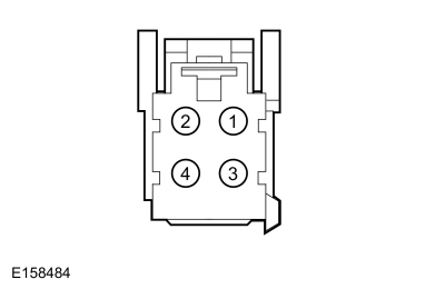 C3005-1, Component Side
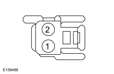 C3850-1, Component Side
|
Refer to Wiring Diagrams Cell 119 for schematic and connector information. Normal Operation and Fault Conditions
REFER to: Front Seats - System Operation and Component Description (501-10A Front Seats, Description and Operation). DTC Fault Trigger Conditions
Possible Sources
Visual Inspection and Pre-checks
NOTE: The SRS must be fully operational and free of faults before releasing the vehicle to the customer. |
||||||||||||||||||||||||
| AF1 CHECK FOR SCMF (REAR SEAT CLIMATE CONTROL MODULE) DIAGNOSTIC TROUBLE CODES (DTCS) | ||||||||||||||||||||||||
Are any SCMF Diagnostic Trouble Codes (DTCs) present?
|
||||||||||||||||||||||||
| AF2 CHECK THE FCIM (FRONT CONTROLS INTERFACE MODULE) HEATED SEAT CONTROL SWITCH PID (PARAMETER IDENTIFICATION) | ||||||||||||||||||||||||
Does the PID agree with the seat control switch when it is pressed and released?
|
||||||||||||||||||||||||
| AF3 CHECK THE HEATED SEAT VOLTAGE SUPPLY CIRCUITS FOR AN OPEN | ||||||||||||||||||||||||
Are the voltages greater than 11 volts?
|
||||||||||||||||||||||||
| AF4 CHECK THE HEATED SEAT GROUND CIRCUITS FOR AN OPEN | ||||||||||||||||||||||||
Are the resistances less than 3 ohms?
|
||||||||||||||||||||||||
| AF5 CHECK THE HEATER ELEMENT POWER CIRCUIT FOR A SHORT TO VOLTAGE | ||||||||||||||||||||||||
Is any voltage present?
|
||||||||||||||||||||||||
| AF6 CHECK THE HEATER ELEMENT POWER CIRCUIT FOR AN OPEN OR SHORT TO GROUND | ||||||||||||||||||||||||
Are the resistances greater than 10,000 ohms between the seat cushion heater mat and ground; and less than 3 ohms between the seat cushion heater mat and the SCMB ?
|
||||||||||||||||||||||||
| AF7 CHECK THE HEATED SEAT TEMPERATURE SENSOR CIRCUIT FOR A SHORT TO VOLTAGE | ||||||||||||||||||||||||
Is any voltage present?
|
||||||||||||||||||||||||
| AF8 CHECK THE HEATED SEAT TEMPERATURE SENSOR CIRCUIT FOR AN OPEN OR SHORT TO GROUND | ||||||||||||||||||||||||
Is the resistance greater than 10,000 ohms between the seat cushion heater mat and ground; and less than 3 ohms between the seat cushion heater mat and the SCMB ?
|
||||||||||||||||||||||||
| AF9 CHECK THE HEATED SEAT TEMPERATURE SENSOR RETURN CIRCUIT FOR AN OPEN OR SHORT TO GROUND | ||||||||||||||||||||||||
Is the resistance greater than 10,000 ohms between the seat cushion heater mat and ground; and less than 3 ohms between the seat cushion heater mat and the SCMB ?
|
||||||||||||||||||||||||
| AF10 CHECK THE HEATER ELEMENT GROUND CIRCUIT FOR AN OPEN | ||||||||||||||||||||||||
Are the resistances less than 3 ohms?
|
||||||||||||||||||||||||
| AF11 CHECK THE CUSHION HEATED SEAT MAT FOR AN OPEN OR SHORT TO GROUND | ||||||||||||||||||||||||
Is the resistance between 0.6 and 2 ohms between pins 1 and 4; and greater than 10,000 ohms between pin 1 and ground?
|
||||||||||||||||||||||||
| AF12 CHECK THE BACKREST HEATED SEAT MAT FOR AN OPEN OR SHORT TO GROUND | ||||||||||||||||||||||||
Is the resistance between 0.6 and 2 ohms between pins 1 and 2; and greater than 10,000 ohms between pin 2 and ground?
|
||||||||||||||||||||||||
| AF13 CHECK THE CIRCUIT BETWEEN THE CUSHION HEATER MAT AND BACKREST HEATER MAT FOR AN OPEN AND SHORT TO GROUND | ||||||||||||||||||||||||
Is the resistance greater than 10,000 ohms between the right seat cushion heater mat and ground; and less than 3 ohms between the right seat cushion heater mat and the backrest heater mat?
|
||||||||||||||||||||||||
| AF14 CHECK THE HEATED SEAT TEMPERATURE SENSOR FOR AN OPEN OR SHORT TO GROUND | ||||||||||||||||||||||||
Is the resistance between 300 and 300,000 ohms between pins 2 and 3; and greater than 10,000 ohms between pin 2 and ground?
|
||||||||||||||||||||||||
| AF15 CHECK THE SCMB (PASSENGER FRONT SEAT MODULE) OPERATION | ||||||||||||||||||||||||
Is the concern still present?
|
||||||||||||||||||||||||
| AF16 VERIFY THE SRS (SUPPLEMENTAL RESTRAINT SYSTEM) PROVES OUT SUCCESSFULLY | ||||||||||||||||||||||||
Did the SRS prove out successfully?
|
|
Refer to Wiring Diagrams Cell 119 for schematic and connector information. Normal Operation and Fault Conditions
REFER to: Front Seats - System Operation and Component Description (501-10A Front Seats, Description and Operation). DTC Fault Trigger Conditions
Possible Sources
|
||||||||||||||||||||||||||||||||||
| AG1 CHECK THE DRIVER HEATED SEAT OPERATION | ||||||||||||||||||||||||||||||||||
Does the driver heated seat operate correctly?
|
||||||||||||||||||||||||||||||||||
| AG2 CHECK THE FCIM (FRONT CONTROLS INTERFACE MODULE) VENTILATED SEAT CONTROL SWITCH PID (PARAMETER IDENTIFICATION) | ||||||||||||||||||||||||||||||||||
Does the PID agree with the seat control switch when it is pressed and released?
|
||||||||||||||||||||||||||||||||||
| AG3 CHECK THE BLOWER MOTOR AND DSM (DRIVER FRONT SEAT MODULE) CONNECTIONS | ||||||||||||||||||||||||||||||||||
Is the concern still present?
|
||||||||||||||||||||||||||||||||||
| AG4 CHECK THE BLOWER MOTOR CIRCUITS FOR A SHORT TO VOLTAGE | ||||||||||||||||||||||||||||||||||
Is any voltage present?
|
||||||||||||||||||||||||||||||||||
| AG5 CHECK THE BLOWER MOTOR CIRCUITS FOR A SHORT TO GROUND | ||||||||||||||||||||||||||||||||||
Are the resistances greater than 10,000 ohms?
|
||||||||||||||||||||||||||||||||||
| AG6 CHECK THE BLOWER MOTOR CIRCUITS FOR AN OPEN | ||||||||||||||||||||||||||||||||||
Are the resistances less than 3 ohms?
|
||||||||||||||||||||||||||||||||||
| AG7 CHECK THE BLOWER MOTOR OPERATION | ||||||||||||||||||||||||||||||||||
Is the concern still present?
|
||||||||||||||||||||||||||||||||||
| AG8 CHECK THE DSM (DRIVER FRONT SEAT MODULE) OPERATION | ||||||||||||||||||||||||||||||||||
Is the concern still present?
|
||||||||||||||||||||||||||||||||||
| AG9 VERIFY THE SRS (SUPPLEMENTAL RESTRAINT SYSTEM) PROVES OUT SUCCESSFULLY | ||||||||||||||||||||||||||||||||||
Did the SRS prove out successfully?
|
|
Refer to Wiring Diagrams Cell 119 for schematic and connector information. Normal Operation and Fault Conditions
REFER to: Front Seats - System Operation and Component Description (501-10A Front Seats, Description and Operation). DTC Fault Trigger Conditions
Possible Sources
|
||||||||||||||||||||||||||||||||||
| AH1 CHECK THE PASSENGER HEATED SEAT OPERATION | ||||||||||||||||||||||||||||||||||
Does the passenger heated seat operate correctly?
|
||||||||||||||||||||||||||||||||||
| AH2 CHECK THE FCIM (FRONT CONTROLS INTERFACE MODULE) VENTILATED SEAT CONTROL SWITCH PID (PARAMETER IDENTIFICATION) | ||||||||||||||||||||||||||||||||||
Does the PID agree with the seat control switch when it is pressed and released?
|
||||||||||||||||||||||||||||||||||
| AH3 CHECK THE BLOWER MOTOR AND SCMB (PASSENGER FRONT SEAT MODULE) CONNECTIONS | ||||||||||||||||||||||||||||||||||
Is the concern still present?
|
||||||||||||||||||||||||||||||||||
| AH4 CHECK THE BLOWER MOTOR CIRCUITS FOR A SHORT TO VOLTAGE | ||||||||||||||||||||||||||||||||||
Is any voltage present?
|
||||||||||||||||||||||||||||||||||
| AH5 CHECK THE BLOWER MOTOR CIRCUITS FOR A SHORT TO GROUND | ||||||||||||||||||||||||||||||||||
Are the resistances greater than 10,000 ohms?
|
||||||||||||||||||||||||||||||||||
| AH6 CHECK THE BLOWER MOTOR CIRCUITS FOR AN OPEN | ||||||||||||||||||||||||||||||||||
Are the resistances less than 3 ohms?
|
||||||||||||||||||||||||||||||||||
| AH7 CHECK THE BLOWER MOTOR OPERATION | ||||||||||||||||||||||||||||||||||
Is the concern still present?
|
||||||||||||||||||||||||||||||||||
| AH8 CHECK THE SCMB (PASSENGER FRONT SEAT MODULE) OPERATION | ||||||||||||||||||||||||||||||||||
Is the concern still present?
|
||||||||||||||||||||||||||||||||||
| AH9 VERIFY THE SRS (SUPPLEMENTAL RESTRAINT SYSTEM) PROVES OUT SUCCESSFULLY | ||||||||||||||||||||||||||||||||||
Did the SRS prove out successfully?
|
|
Refer to Wiring Diagrams Cell 14 for schematic and connector information. Normal Operation and Fault Conditions
REFER to: Front Seats - System Operation and Component Description (501-10A Front Seats, Description and Operation). The SCME and the BCM communicate using the MS-CAN . DTC Fault Trigger Conditions
Possible Sources
|
||||||
| AI1 VERIFY CUSTOMER CONCERN | ||||||
Is an observable symptom present?
|
||||||
| AI2 CHECK THE COMMUNICATION NETWORK | ||||||
Does the BCM pass the network test?
|
||||||
| AI3 RECHECK THE SCME (FRONT SEAT CLIMATE CONTROL MODULE) DIAGNOSTIC TROUBLE CODES (DTCS) | ||||||
|
NOTE: If new modules were installed prior to the DTC being set, the module configuration may be incorrectly set during PMI or the PMI may not have been carried out.
Is DTC U0140:00 still present?
|
||||||
| AI4 CHECK FOR DTC U0140:00 IN OTHER MODULES | ||||||
|
NOTE: If new modules were installed prior to the DTC being set, the module configuration may be incorrectly set during PMI or the PMI may not have been carried out.
Is DTC U0140:00 set in other modules?
|
|
Refer to Wiring Diagrams Cell 14 for schematic and connector information. Normal Operation and Fault Conditions
REFER to: Front Seats - System Operation and Component Description (501-10A Front Seats, Description and Operation). The SCME and the BCM communicate using the MS-CAN . DTC Fault Trigger Conditions
Possible Sources
|
||||||
| AJ1 VERIFY CUSTOMER CONCERN | ||||||
Is an observable symptom present?
|
||||||
| AJ2 CHECK THE COMMUNICATION NETWORK | ||||||
Does the BCM pass the network test?
|
||||||
| AJ3 RECHECK THE SCMF (REAR SEAT CLIMATE CONTROL MODULE) DIAGNOSTIC TROUBLE CODES (DTCS) | ||||||
|
NOTE: If new modules were installed prior to the DTC being set, the module configuration may be incorrectly set during PMI or the PMI may not have been carried out.
Is DTC U0140:00 still present?
|
||||||
| AJ4 CHECK FOR DTC U0140:00 IN OTHER MODULES | ||||||
|
NOTE: If new modules were installed prior to the DTC being set, the module configuration may be incorrectly set during PMI or the PMI may not have been carried out.
Is DTC U0140:00 set in other modules?
|
|
Refer to Wiring Diagrams Cell 14 for schematic and connector information. Normal Operation and Fault Conditions
REFER to: Front Seats - System Operation and Component Description (501-10A Front Seats, Description and Operation). The SCME and the FCIM communicate using the CAN . DTC Fault Trigger Conditions
Possible Sources
|
||||||
| AK1 VERIFY CUSTOMER CONCERN | ||||||
Is an observable symptom present?
|
||||||
| AK2 CHECK THE COMMUNICATION NETWORK | ||||||
Does the FCIM module pass the network test?
|
||||||
| AK3 RECHECK THE SCME (FRONT SEAT CLIMATE CONTROL MODULE) DIAGNOSTIC TROUBLE CODES (DTCS) | ||||||
|
NOTE: If new modules were installed prior to the DTC being set, the module configuration may be incorrectly set during PMI or the PMI may not have been carried out.
Is DTC U0257:00 still present?
|
||||||
| AK4 CHECK FOR DTC U0257:00 IN OTHER MODULES | ||||||
|
NOTE: If new modules were installed prior to the DTC being set, the module configuration may be incorrectly set during PMI or the PMI may not have been carried out.
Is DTC U0257:00 set in other modules?
|
|
Refer to Wiring Diagrams Cell 14 for schematic and connector information. Normal Operation and Fault Conditions
REFER to: Front Seats - System Operation and Component Description (501-10A Front Seats, Description and Operation). The SCMF and the FCIM communicate using the CAN . DTC Fault Trigger Conditions
Possible Sources
|
||||||
| AL1 VERIFY CUSTOMER CONCERN | ||||||
Is an observable symptom present?
|
||||||
| AL2 CHECK THE COMMUNICATION NETWORK | ||||||
Does the FCIM module pass the network test?
|
||||||
| AL3 RECHECK THE SCMF (REAR SEAT CLIMATE CONTROL MODULE) DIAGNOSTIC TROUBLE CODES (DTCS) | ||||||
|
NOTE: If new modules were installed prior to the DTC being set, the module configuration may be incorrectly set during PMI or the PMI may not have been carried out.
Is DTC U0257:00 still present?
|
||||||
| AL4 CHECK FOR DTC U0257:00 IN OTHER MODULES | ||||||
|
NOTE: If new modules were installed prior to the DTC being set, the module configuration may be incorrectly set during PMI or the PMI may not have been carried out.
Is DTC U0257:00 set in other modules?
|
|
Refer to Wiring Diagrams Cell 119 for schematic and connector information. Normal Operation and Fault Conditions
REFER to: Front Seats - System Operation and Component Description (501-10A Front Seats, Description and Operation). DIAGNOSE any other DSM and SCME Diagnostic Trouble Codes (DTCs)
first. CLEAR the Diagnostic Trouble Codes (DTCs). REPEAT the self-test.
If DTC U1000:00 returns, INSTALL a new DSM . REFER to: Driver Front Seat
Module (DSM) (501-10A Front Seats, Removal and Installation). DTC Fault Trigger Conditions
Possible Sources
|
||||||
| Diagnostic steps are not provided for this symptom or DTC. REFER to: Diagnostic Methods (100-00 General Information, Description and Operation). |
|
Refer to Wiring Diagrams Cell 119 for schematic and connector information. Normal Operation and Fault Conditions
REFER to: Front Seats - System Operation and Component Description (501-10A Front Seats, Description and Operation). DIAGNOSE any other SCMB and SCMF Diagnostic Trouble Codes (DTCs)
first. CLEAR the Diagnostic Trouble Codes (DTCs). REPEAT the self-test.
If DTC U1000:00 returns, INSTALL a new SCMB . REFER to: Driver Front
Seat Module (DSM) (501-10A Front Seats, Removal and Installation). DTC Fault Trigger Conditions
Possible Sources
|
||||||
| Diagnostic steps are not provided for this symptom or DTC. REFER to: Diagnostic Methods (100-00 General Information, Description and Operation). |
|
Refer to Wiring Diagrams Cell 119 for schematic and connector information. Normal Operation and Fault Conditions
REFER to: Front Seats - System Operation and Component Description (501-10A Front Seats, Description and Operation). Using a diagnostic scan tool, CARRY OUT PMI on the SCME . REPEAT the self-test and VERIFY successful PMI . CLEAR the Diagnostic Trouble Codes (DTCs). DTC Fault Trigger Conditions
Possible Sources
|
||||||
| Diagnostic steps are not provided for this symptom or DTC. REFER to: Diagnostic Methods (100-00 General Information, Description and Operation). |
|
Refer to Wiring Diagrams Cell 119 for schematic and connector information. Normal Operation and Fault Conditions
REFER to: Front Seats - System Operation and Component Description (501-10A Front Seats, Description and Operation). Using a diagnostic scan tool, CARRY OUT PMI on the SCMF . REPEAT the self-test and VERIFY successful PMI . CLEAR the Diagnostic Trouble Codes (DTCs). DTC Fault Trigger Conditions
Possible Sources
|
||||||
| Diagnostic steps are not provided for this symptom or DTC. REFER to: Diagnostic Methods (100-00 General Information, Description and Operation). |
|
Refer to Wiring Diagrams Cell 119 for schematic and connector information. Normal Operation and Fault Conditions
REFER to: Front Seats - System Operation and Component Description (501-10A Front Seats, Description and Operation). INSTALL a new DSM . REFER to: Driver Front Seat Module (DSM) (501-10A Front Seats, Removal and Installation). DTC Fault Trigger Conditions
Possible Sources
|
||||||
| Diagnostic steps are not provided for this symptom or DTC. REFER to: Diagnostic Methods (100-00 General Information, Description and Operation). |
|
Refer to Wiring Diagrams Cell 119 for schematic and connector information. Normal Operation and Fault Conditions
REFER to: Front Seats - System Operation and Component Description (501-10A Front Seats, Description and Operation). INSTALL a new SCMB . REFER to: Driver Front Seat Module (DSM) (501-10A Front Seats, Removal and Installation). DTC Fault Trigger Conditions
Possible Sources
|
||||||
| Diagnostic steps are not provided for this symptom or DTC. REFER to: Diagnostic Methods (100-00 General Information, Description and Operation). |
|
Refer to Wiring Diagrams Cell 123 for schematic and connector information. Normal Operation and Fault Conditions
REFER to: Front Seats - System Operation and Component Description (501-10A Front Seats, Description and Operation). DTC Fault Trigger Conditions
Possible Sources
Visual Inspection and Pre-checks
|
||||||||||||||||||||||||
| AS1 CHECK THE CLIMATE CONTROL OPERATION FROM THE TOUCHSCREEN | ||||||||||||||||||||||||
Did the climate control system features operate correctly from the touchscreen?
|
||||||||||||||||||||||||
| AS2 CHECK THE SCMG (DRIVER MULTI-CONTOUR SEAT MODULE) DIAGNOSTIC TROUBLE CODES (DTCS) | ||||||||||||||||||||||||
Were any Diagnostic Trouble Codes (DTCs) retrieved?
|
||||||||||||||||||||||||
| AS3 CHECK THE FRONT MULTI-CONTOUR CONTROL PUMP FEED FOR A SHORT TO GROUND | ||||||||||||||||||||||||
Is the resistance greater than 10,000 ohms?
|
||||||||||||||||||||||||
| AS4 VERIFY THE FRONT MULTI-CONTOUR CONTROL PUMP OPERATES | ||||||||||||||||||||||||
Is the front multi-contour control pump on?
|
||||||||||||||||||||||||
| AS5 CHECK THE FRONT MULTI-CONTOUR CONTROL PUMP CIRCUITS FOR AN OPEN | ||||||||||||||||||||||||
Are the resistances less than 3 ohms?
|
||||||||||||||||||||||||
| AS6 CHECK THE FRONT MULTI-CONTOUR CONTROL PUMP HOSES FOR CORRECT INSTALLATION OR DAMAGE | ||||||||||||||||||||||||
Are the front multi-contour control pump hoses installed correctly with no damage?
|
||||||||||||||||||||||||
| AS7 CHECK THE BACKREST HOSE(S) FOR CORRECT INSTALLATION, RESTRICTION OR DAMAGE | ||||||||||||||||||||||||
Are the backrest hoses installed correctly with no damage or restrictions?
|
||||||||||||||||||||||||
| AS8 CHECK THE FRONT SEAT BACKREST ADJUSTER POWER CIRCUIT FOR AN OPEN | ||||||||||||||||||||||||
Is the voltage greater than 11 volts?
|
||||||||||||||||||||||||
| AS9 CHECK THE FRONT SEAT BACKREST ADJUSTER GROUND CIRCUIT FOR AN OPEN | ||||||||||||||||||||||||
Is the resistance less than 3 ohms?
|
||||||||||||||||||||||||
| AS10 CHECK THE FRONT SEAT BACKREST ADJUSTER LIN (LOCAL INTERCONNECT NETWORK) CIRCUIT FOR A SHORT TO VOLTAGE | ||||||||||||||||||||||||
Is any voltage present?
|
||||||||||||||||||||||||
| AS11 CHECK THE FRONT SEAT BACKREST ADJUSTER LIN (LOCAL INTERCONNECT NETWORK) CIRCUIT FOR A SHORT TO GROUND | ||||||||||||||||||||||||
Is the resistance greater than 10,000 ohms?
|
||||||||||||||||||||||||
| AS12 CHECK THE FRONT SEAT BACKREST ADJUSTER LIN (LOCAL INTERCONNECT NETWORK) CIRCUIT FOR AN OPEN | ||||||||||||||||||||||||
Is the resistance less than 3 ohms?
|
||||||||||||||||||||||||
| AS13 CHECK THE CUSHION HOSE(S) FOR CORRECT INSTALLATION, RESTRICTION OR DAMAGE | ||||||||||||||||||||||||
Are the cushion hoses installed correctly with no damage or restrictions?
|
||||||||||||||||||||||||
| AS14 CHECK THE FRONT SEAT CUSHION ADJUSTER POWER CIRCUIT FOR AN OPEN | ||||||||||||||||||||||||
Is the voltage greater than 11 volts?
|
||||||||||||||||||||||||
| AS15 CHECK THE FRONT SEAT CUSHION ADJUSTER GROUND CIRCUIT FOR AN OPEN | ||||||||||||||||||||||||
Is the resistance less than 3 ohms?
|
||||||||||||||||||||||||
| AS16 CHECK THE FRONT SEAT CUSHION ADJUSTER LIN (LOCAL INTERCONNECT NETWORK) CIRCUIT FOR A SHORT TO VOLTAGE | ||||||||||||||||||||||||
Is any voltage present?
|
||||||||||||||||||||||||
| AS17 CHECK THE FRONT SEAT CUSHION ADJUSTER LIN (LOCAL INTERCONNECT NETWORK) CIRCUIT FOR A SHORT TO GROUND | ||||||||||||||||||||||||
Is the resistance greater than 10,000 ohms?
|
||||||||||||||||||||||||
| AS18 CHECK THE FRONT SEAT CUSHION ADJUSTER LIN (LOCAL INTERCONNECT NETWORK) CIRCUIT FOR AN OPEN | ||||||||||||||||||||||||
Is the resistance less than 3 ohms?
|
||||||||||||||||||||||||
| AS19 CHECK THE SCMG (DRIVER MULTI-CONTOUR SEAT MODULE) OPERATION | ||||||||||||||||||||||||
Is the concern still present?
|
||||||||||||||||||||||||
| AS20 CHECK THE SCMG (DRIVER MULTI-CONTOUR SEAT MODULE) OPERATION | ||||||||||||||||||||||||
Is the concern still present?
|
||||||||||||||||||||||||
| AS21 VERIFY THE SRS (SUPPLEMENTAL RESTRAINT SYSTEM) PROVES OUT SUCCESSFULLY | ||||||||||||||||||||||||
Did the SRS prove out successfully?
|
|
Refer to Wiring Diagrams Cell 123 for schematic and connector information. Normal Operation and Fault Conditions
REFER to: Front Seats - System Operation and Component Description (501-10A Front Seats, Description and Operation). DTC Fault Trigger Conditions
Possible Sources
Visual Inspection and Pre-checks
|
||||||||||||||||||||||||
| AT1 CHECK THE CLIMATE CONTROL OPERATION FROM THE TOUCHSCREEN | ||||||||||||||||||||||||
Did the climate control system features operate correctly from the touchscreen?
|
||||||||||||||||||||||||
| AT2 CHECK THE SCMH (PASSENGER MULTI-CONTOUR SEAT MODULE) DIAGNOSTIC TROUBLE CODES (DTCS) | ||||||||||||||||||||||||
Were any Diagnostic Trouble Codes (DTCs) retrieved?
|
||||||||||||||||||||||||
| AT3 CHECK THE FRONT MULTI-CONTOUR CONTROL PUMP FEED FOR A SHORT TO GROUND | ||||||||||||||||||||||||
Is the resistance greater than 10,000 ohms?
|
||||||||||||||||||||||||
| AT4 VERIFY THE FRONT MULTI-CONTOUR CONTROL PUMP OPERATES | ||||||||||||||||||||||||
Is the front multi-contour control pump on?
|
||||||||||||||||||||||||
| AT5 CHECK THE FRONT MULTI-CONTOUR CONTROL PUMP CIRCUITS FOR AN OPEN | ||||||||||||||||||||||||
Are the resistances less than 3 ohms?
|
||||||||||||||||||||||||
| AT6 CHECK THE FRONT MULTI-CONTOUR CONTROL PUMP HOSES FOR CORRECT INSTALLATION OR DAMAGE | ||||||||||||||||||||||||
Are the front multi-contour control pump hoses installed correctly with no damage?
|
||||||||||||||||||||||||
| AT7 CHECK THE BACKREST HOSE(S) FOR CORRECT INSTALLATION, RESTRICTION OR DAMAGE | ||||||||||||||||||||||||
Are the backrest hoses installed correctly with no damage or restrictions?
|
||||||||||||||||||||||||
| AT8 CHECK THE FRONT SEAT BACKREST ADJUSTER POWER CIRCUIT FOR AN OPEN | ||||||||||||||||||||||||
Is the voltage greater than 11 volts?
|
||||||||||||||||||||||||
| AT9 CHECK THE FRONT SEAT BACKREST ADJUSTER GROUND CIRCUIT FOR AN OPEN | ||||||||||||||||||||||||
Is the resistance less than 3 ohms?
|
||||||||||||||||||||||||
| AT10 CHECK THE FRONT SEAT BACKREST ADJUSTER LIN (LOCAL INTERCONNECT NETWORK) CIRCUIT FOR A SHORT TO VOLTAGE | ||||||||||||||||||||||||
Is any voltage present?
|
||||||||||||||||||||||||
| AT11 CHECK THE FRONT SEAT BACKREST ADJUSTER LIN (LOCAL INTERCONNECT NETWORK) CIRCUIT FOR A SHORT TO GROUND | ||||||||||||||||||||||||
Is the resistance greater than 10,000 ohms?
|
||||||||||||||||||||||||
| AT12 CHECK THE FRONT SEAT BACKREST ADJUSTER LIN (LOCAL INTERCONNECT NETWORK) CIRCUIT FOR AN OPEN | ||||||||||||||||||||||||
Is the resistance less than 3 ohms?
|
||||||||||||||||||||||||
| AT13 CHECK THE CUSHION HOSE(S) FOR CORRECT INSTALLATION, RESTRICTION OR DAMAGE | ||||||||||||||||||||||||
Are the cushion hoses installed correctly with no damage or restrictions?
|
||||||||||||||||||||||||
| AT14 CHECK THE FRONT SEAT CUSHION ADJUSTER POWER CIRCUIT FOR AN OPEN | ||||||||||||||||||||||||
Is the voltage greater than 11 volts?
|
||||||||||||||||||||||||
| AT15 CHECK THE FRONT SEAT CUSHION ADJUSTER GROUND CIRCUIT FOR AN OPEN | ||||||||||||||||||||||||
Is the resistance less than 3 ohms?
|
||||||||||||||||||||||||
| AT16 CHECK THE FRONT SEAT CUSHION ADJUSTER LIN (LOCAL INTERCONNECT NETWORK) CIRCUIT FOR A SHORT TO VOLTAGE | ||||||||||||||||||||||||
Is any voltage present?
|
||||||||||||||||||||||||
| AT17 CHECK THE FRONT SEAT CUSHION ADJUSTER LIN (LOCAL INTERCONNECT NETWORK) CIRCUIT FOR A SHORT TO GROUND | ||||||||||||||||||||||||
Is the resistance greater than 10,000 ohms?
|
||||||||||||||||||||||||
| AT18 CHECK THE FRONT SEAT CUSHION ADJUSTER LIN (LOCAL INTERCONNECT NETWORK) CIRCUIT FOR AN OPEN | ||||||||||||||||||||||||
Is the resistance less than 3 ohms?
|
||||||||||||||||||||||||
| AT19 CHECK THE SCMH (PASSENGER MULTI-CONTOUR SEAT MODULE) OPERATION | ||||||||||||||||||||||||
Is the concern still present?
|
||||||||||||||||||||||||
| AT20 CHECK THE SCMH (PASSENGER MULTI-CONTOUR SEAT MODULE) OPERATION | ||||||||||||||||||||||||
Is the concern still present?
|
||||||||||||||||||||||||
| AT21 VERIFY THE SRS (SUPPLEMENTAL RESTRAINT SYSTEM) PROVES OUT SUCCESSFULLY | ||||||||||||||||||||||||
Did the SRS prove out successfully?
|
|
Refer to Wiring Diagrams Cell 14 for schematic and connector information. Normal Operation and Fault Conditions The SCMG and SCMH communicate to the BCM using the MS-CAN . REFER
to: Front Seats - System Operation and Component Description (501-10A
Front Seats, Description and Operation). DTC Fault Trigger Conditions
Possible Sources
|
|||||||||
| AU1 VERIFY CUSTOMER CONCERN | |||||||||
Is an observable symptom present?
|
|||||||||
| AU2 CHECK THE COMMUNICATION NETWORK | |||||||||
Does the BCM pass the network test?
|
|||||||||
| AU3 RECHECK THE SCMG (DRIVER MULTI-CONTOUR SEAT MODULE) / SCMH (PASSENGER MULTI-CONTOUR SEAT MODULE) DIAGNOSTIC TROUBLE CODES (DTCS) | |||||||||
|
NOTE: If new modules were installed prior to the DTC being set, the module configuration may be incorrectly set during PMI or the PMI may not have been carried out.
Is DTC U0140:00 still present?
|
|||||||||
| AU4 CHECK FOR DTC U0140:00 IN OTHER MODULES | |||||||||
|
NOTE: If new modules were installed prior to the DTC being set, the module configuration may be incorrectly set during PMI or the PMI may not have been carried out.
Is DTC U0140:00 set in other modules?
|
|
Refer to Wiring Diagrams Cell 14 for schematic and connector information. Normal Operation and Fault Conditions The SCMG / SCMH communicate to the DSM using the CAN . REFER to:
Front Seats - System Operation and Component Description (501-10A Front
Seats, Description and Operation). DTC Fault Trigger Conditions
Possible Sources
|
|||||||||
| AV1 VERIFY CUSTOMER CONCERN | |||||||||
Is an observable symptom present?
|
|||||||||
| AV2 CHECK THE COMMUNICATION NETWORK | |||||||||
Does the DSM pass the network test?
|
|||||||||
| AV3 RECHECK THE SCMG (DRIVER MULTI-CONTOUR SEAT MODULE) / SCMH (PASSENGER MULTI-CONTOUR SEAT MODULE) DIAGNOSTIC TROUBLE CODES (DTCS) | |||||||||
|
NOTE: If new modules were installed prior to the DTC being set, the module configuration may be incorrectly set during PMI or the PMI may not have been carried out.
Is DTC U0208:00 still present?
|
|||||||||
| AV4 CHECK FOR DTC U0208:00 IN OTHER MODULES | |||||||||
|
NOTE: If new modules were installed prior to the DTC being set, the module configuration may be incorrectly set during PMI or the PMI may not have been carried out.
Is DTC U0208:00 set in other modules?
|
|
Refer to Wiring Diagrams Cell 14 for schematic and connector information. Normal Operation and Fault Conditions The SCMH communicates to the SCMG using the CAN . REFER to: Front
Seats - System Operation and Component Description (501-10A Front Seats,
Description and Operation). DTC Fault Trigger Conditions
Possible Sources
|
||||||
| AW1 VERIFY CUSTOMER CONCERN | ||||||
Is an observable symptom present?
|
||||||
| AW2 CHECK THE COMMUNICATION NETWORK | ||||||
Does the SCMG pass the network test?
|
||||||
| AW3 RECHECK THE SCMH (PASSENGER MULTI-CONTOUR SEAT MODULE) DIAGNOSTIC TROUBLE CODES (DTCS) | ||||||
|
NOTE: If new modules were installed prior to the DTC being set, the module configuration may be incorrectly set during PMI or the PMI may not have been carried out.
Is DTC U024B:00 still present?
|
||||||
| AW4 CHECK FOR DTC U024B:00 IN OTHER MODULES | ||||||
|
NOTE: If new modules were installed prior to the DTC being set, the module configuration may be incorrectly set during PMI or the PMI may not have been carried out.
Is DTC U024B:00 set in other modules?
|
|
Refer to Wiring Diagrams Cell 14 for schematic and connector information. Normal Operation and Fault Conditions
REFER to: Front Seats - System Operation and Component Description (501-10A Front Seats, Description and Operation). The SCMG and SCMH communicate to the APIM using the CAN . DTC Fault Trigger Conditions
Possible Sources
|
|||||||||
| AX1 VERIFY CUSTOMER CONCERN | |||||||||
Is an observable symptom present?
|
|||||||||
| AX2 CHECK THE COMMUNICATION NETWORK | |||||||||
Does the APIM pass the network test?
|
|||||||||
| AX3 RECHECK THE SCMG (DRIVER MULTI-CONTOUR SEAT MODULE) / SCMH (PASSENGER MULTI-CONTOUR SEAT MODULE) DIAGNOSTIC TROUBLE CODES (DTCS) | |||||||||
|
NOTE: If new modules were installed prior to the DTC being set, the module configuration may be incorrectly set during PMI or the PMI may not have been carried out.
Is DTC U0253:00 still present?
|
|||||||||
| AX4 CHECK FOR DTC U0253:00 IN OTHER MODULES | |||||||||
|
NOTE: If new modules were installed prior to the DTC being set, the module configuration may be incorrectly set during PMI or the PMI may not have been carried out.
Is DTC U0253:00 set in other modules?
|
|
Refer to Wiring Diagrams Cell 14 for schematic and connector information. Normal Operation and Fault Conditions
REFER to: Front Seats - System Operation and Component Description (501-10A Front Seats, Description and Operation). The SCMG and SCMH communicate to the FCIM using the CAN . DTC Fault Trigger Conditions
Possible Sources
|
|||||||||
| AY1 VERIFY CUSTOMER CONCERN | |||||||||
Is an observable symptom present?
|
|||||||||
| AY2 CHECK THE COMMUNICATION NETWORK | |||||||||
Does the FCIM pass the network test?
|
|||||||||
| AY3 RECHECK THE SCMG (DRIVER MULTI-CONTOUR SEAT MODULE) / SCMH (PASSENGER MULTI-CONTOUR SEAT MODULE) DIAGNOSTIC TROUBLE CODES (DTCS) | |||||||||
|
NOTE: If new modules were installed prior to the DTC being set, the module configuration may be incorrectly set during PMI or the PMI may not have been carried out.
Is DTC U0256:00 still present?
|
|||||||||
| AY4 CHECK FOR DTC U0256:00 IN OTHER MODULES | |||||||||
|
NOTE: If new modules were installed prior to the DTC being set, the module configuration may be incorrectly set during PMI or the PMI may not have been carried out.
Is DTC U0256:00 set in other modules?
|
|
Refer to Wiring Diagrams Cell 14 for schematic and connector information. Normal Operation and Fault Conditions
REFER to: Front Seats - System Operation and Component Description (501-10A Front Seats, Description and Operation). The SCMG and SCMH communicate to the OCSM using the CAN . DTC Fault Trigger Conditions
Possible Sources
|
||||||
| AZ1 VERIFY CUSTOMER CONCERN | ||||||
Is an observable symptom present?
|
||||||
| AZ2 CHECK THE COMMUNICATION NETWORK | ||||||
Does the OCSM pass the network test?
|
||||||
| AZ3 RECHECK THE SCMH (PASSENGER MULTI-CONTOUR SEAT MODULE) DIAGNOSTIC TROUBLE CODES (DTCS) | ||||||
|
NOTE: If new modules were installed prior to the DTC being set, the module configuration may be incorrectly set during PMI or the PMI may not have been carried out.
Is DTC U0455:82 still present?
|
||||||
| AZ4 CHECK FOR DTC U0455:82 IN OTHER MODULES | ||||||
|
NOTE: If new modules were installed prior to the DTC being set, the module configuration may be incorrectly set during PMI or the PMI may not have been carried out.
Is DTC U0455:82 set in other modules?
|
|
Refer to Wiring Diagrams Cell 123 for schematic and connector information. Normal Operation and Fault Conditions Using a diagnostic scan tool, CARRY OUT PMI on the SCMG / SCMH .
REPEAT the self-test and VERIFY successful PMI . REFER to: Front Seats -
System Operation and Component Description (501-10A Front Seats,
Description and Operation). DTC Fault Trigger Conditions
Possible Sources
|
|||||||||
| Diagnostic steps are not provided for this symptom or DTC. REFER to: Diagnostic Methods (100-00 General Information, Description and Operation). |
|
Refer to Wiring Diagrams Cell 123 for schematic and connector information. Normal Operation and Fault Conditions INSTALL a new front seat power lumbar assembly. REFER to: Front Seat
Power Lumbar Assembly - Vehicles With: Multi-Contour Seats (501-10A
Front Seats, Removal and Installation). DTC Fault Trigger Conditions
Possible Sources
|
|||||||||
| Diagnostic steps are not provided for this symptom or DTC. REFER to: Diagnostic Methods (100-00 General Information, Description and Operation). |

 Seat Heater Mat Installation. General Procedures
Repair
NOTE:
Click here to view a video version of the seat heater mat removal and installation. View
NOTE:
Always install a new heater mat...
Other information:
Lincoln Navigator 2018-2026 Workshop Manual: Rear Drive Axle and Differential - Vehicles With: Electronic Limited-Slip Differential - System Operation and Component Description. Description and Operation
System Diagram E366578 *.sttxt { visibility: hidden; } *.stcallout { visibility: visible; } 1 Clutch Pressure and Temperature Sensor 2 ABS ..
Lincoln Navigator 2018-2026 Workshop Manual: Vehicle Dynamics Control Module (VDM). Removal and Installation
Removal NOTICE: Electronic modules are sensitive to static electrical charges. If exposed to these charges, damage may result. NOTE: Removal steps in this procedure may contain installation details. NOTE: The current PMI process must begin with the current VDM installed. If the current VDM does not respond to the diagnostic scan tool, the tool may prompt for As-Bu..
Categories
- Manuals Home
- 4th Gen Lincoln Navigator Service Manual (2018 - 2026)
- Rear Bumper. Removal and Installation
- Remote Function Actuator (RFA) Module. Removal and Installation
- Power Running Board (PRB). Diagnosis and Testing
- All Terrain Control Module (ATCM). Removal and Installation
- Transmission Fluid Drain and Refill. General Procedures
Diagnostic Methods. Description and Operation
This document provides critical diagnostic knowledge required for successful repair outcomes. It identifies technical competencies expected by users of this manual.
Ford Diagnostic Assumptions
Ford diagnostics assume the vehicle concern described by the test title is currently present. Exceptions to this rule are noted in each test. Do not replace modules or other components as directed by a diagnostic if the concern is not present at the time of testing.