Lincoln Navigator: Full Frame and Body Mounting / Front Lower Control Arm Bracket. Removal and Installation
Special Tool(s) / General Equipment
| Grinder | |
| 8 mm Drill Bit | |
| MIG/MAG Welding Equipment | |
| Locking Pliers |
Removal
-
Restore the vehicle to manufacturer's dimensions if required.
Refer to: Body and Frame (501-26 Body Repairs - Vehicle Specific Information and Tolerance Checks, Description and Operation).
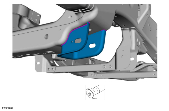
NOTE: The frame mounted lower control arm brackets are retained to the frame #1 crossmember by welds.
NOTE: LH side shown, RH side similar.
-
Remove the lower control arm from the affected side if equipped with 2WD .
Refer to: Lower Arm (204-01A Front Suspension - LHD RWD, Removal and Installation).
-
Remove the lower control arm from the affected side if equipped with 4WD
Refer to: Lower Arm (204-01B Front Suspension - LHD 4WD, Removal and Installation).
-
NOTE: Be careful not to cut into the frame cross member, it will be reused.
Grind the welds holding the front lower control arm mounting bracket to the frame, and remove the control arm bracket.
-
Clean the areas of the frame where the welds were ground.
Use the General Equipment: Grinder
-
Clean the areas of the frame where the welds were ground.
 |
Installation
-
Refer to: Joining Techniques (501-25 Body Repairs - General Information, General Procedures).
-
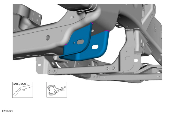
Loosely clamp the replacement bracket in a preliminary
position. Perform measurements to verify proper placement of the new
bracket, then clamp firmly into position.
-
With all measurements verified and the new bracket
in proper position, tack-weld the new bracket in place to the frame
crossmember.
Use the General Equipment: MIG/MAG Welding Equipment
Use the General Equipment: Locking Pliers
-
With all measurements verified and the new bracket
in proper position, tack-weld the new bracket in place to the frame
crossmember.
 |
-
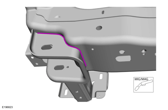
Re-check measurements, then solid weld the bracket to the frame crossmember.
Use the General Equipment: MIG/MAG Welding Equipment
 |
-
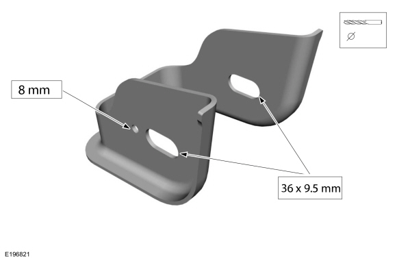
NOTE: The bracket is supplied without the lower control arm mounting holes present. It is intended that the required holes be added to the bracket after the bracket is installed to the frame cross member and proper measurements have been made to properly position the required holes on the bracket.
Drill the control arm bracket mounting holes.
Use the General Equipment: 8 mm Drill Bit
 |
-
Metal finish the repair area using typical metal finishing techniques.
-
Restore corrosion protection.
Refer to: Corrosion Prevention (501-25 Body Repairs - General Information, General Procedures).
-
Install the lower control arm from the affected side if equipped with 2WD .
Refer to: Lower Arm (204-01A Front Suspension - LHD RWD, Removal and Installation).
-
Install the lower control arm from the affected side if equipped with 4WD .
Refer to: Lower Arm (204-01B Front Suspension - LHD 4WD, Removal and Installation).
 Front Crossmember. Removal and Installation
Removal
WARNING:
Frame rail crush zones absorb crash energy during a
collision and must be replaced if damaged. Prior to replacement of frame
rail crush zones, straighten damaged frame rails to correct frame
dimensions...
 Trailer Hitch. Removal and Installation
Removal
NOTE:
Removal steps in this procedure may contain installation details.
Remove the rear bumper cover.
Refer to: Rear Bumper Cover (501-19 Bumpers, Removal and Installation)...
Other information:
Lincoln Navigator 2018-2026 Workshop Manual: Inner Constant Velocity (CV) Joint Boot. Removal and Installation
Special Tool(s) / General Equipment Flat Headed Screw Driver Boot Clamp Pliers Rubber Mallet Three Leg Puller Materials Name Specification Motorcraft® Constant Velocity Joint GreaseXG-5 WSS-M1C258-A1 Removal Remove the halfshaft...
Lincoln Navigator 2018-2026 Workshop Manual: Hood. Removal and Installation
Removal NOTE: Removal steps in this procedure may contain installation details. NOTE: RH side shown, LH side similar. On both sides. Index-mark the hood hinge location to aid in hood installation. NOTICE: Support the hood before removing the strut...
Categories
- Manuals Home
- 4th Gen Lincoln Navigator Service Manual (2018 - 2026)
- Vehicle Dynamics Control Module (VDM). Removal and Installation
- Identification Codes. Description and Operation
- Head Up Display (HUD) Module Calibration. General Procedures
- All Terrain Control Module (ATCM). Removal and Installation
- Power Running Board (PRB). Diagnosis and Testing
Differential Case Runout Check. General Procedures
Special Tool(s) / General Equipment
 205-1016
Installer, Differential Bearing
TKIT-2014D-ROW2
TKIT-2014D-FL_ROW
 205-153
(T80T-4000-W)
205-153
(T80T-4000-W)
Handle
 205-D061
(D83T-4205-C2)
205-D061
(D83T-4205-C2)
Step Plate Dial Indicator Three Leg Puller Punch