Lincoln Navigator: Full Frame and Body Mounting / Front Crossmember. Removal and Installation
Removal
 WARNING:
Frame rail crush zones absorb crash energy during a
collision and must be replaced if damaged. Prior to replacement of frame
rail crush zones, straighten damaged frame rails to correct frame
dimensions. Failure to follow these instructions may adversely affect
frame rail crush zone performance and may result in serious personal
injury to vehicle occupants in a crash.
WARNING:
Frame rail crush zones absorb crash energy during a
collision and must be replaced if damaged. Prior to replacement of frame
rail crush zones, straighten damaged frame rails to correct frame
dimensions. Failure to follow these instructions may adversely affect
frame rail crush zone performance and may result in serious personal
injury to vehicle occupants in a crash.
NOTICE: Collision damage repair must conform to the instructions contained in this workshop manual. Replacement components must be new, genuine Ford Motor Company parts. Recycled, salvaged, aftermarket or reconditioned parts (including body parts, wheels or safety restraint components) are not authorized by Ford.
NOTE: Removal steps in this procedure may contain installation details.
-
With the vehicle in NEUTRAL, position it on a hoist.
Refer to: Jacking and Lifting (100-02 Jacking and Lifting, Description and Operation).
-
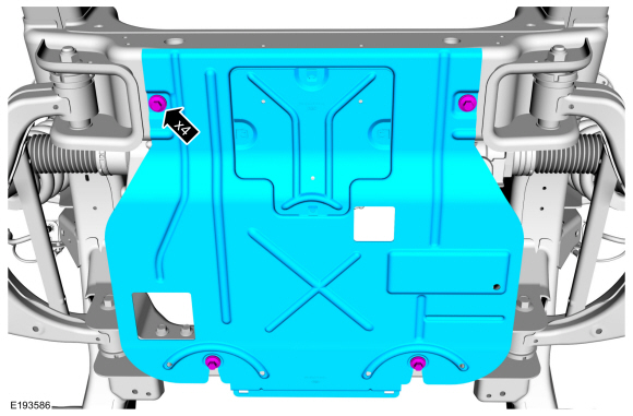
NOTE: If equipped.
Remove the bolts and the underbody shield.
Torque: 30 lb.ft (40 Nm)
 |
-
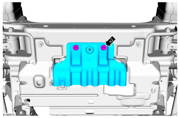
NOTE: If equipped.
Remove the bolts and the underbody shield.
Torque: 30 lb.ft (40 Nm)
 |
-
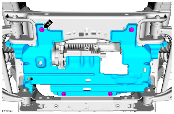
NOTE: If equipped.
NOTE: 4WD shown, RWD similar.
Remove the bolts and the underbody shield.
Torque: 30 lb.ft (40 Nm)
 |
-
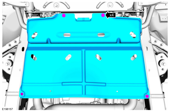
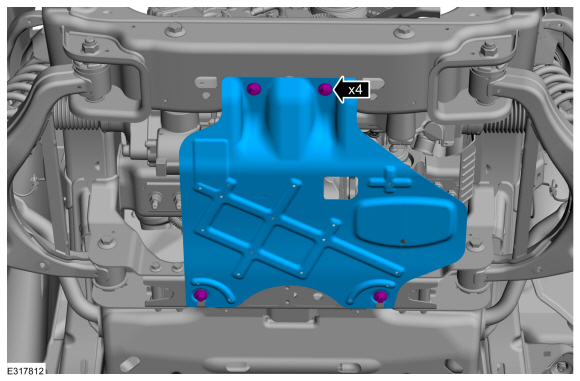
NOTICE: Support the engine rear undershield while the fasteners are being removed and installed. Do not support the engine rear undershield by any less than the total number of fasteners at any time.
Holding the shield in its correct position, remove the fasteners and the engine rear undershield.
Torque: 71 lb.in (8 Nm)
 |
-
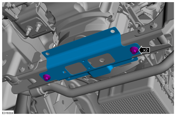
Remove the bolts and the air deflector bracket.
Torque: 30 lb.ft (40 Nm)
 |
-
NOTE: If equipped.
Remove the bolts and the underbody shield.
Torque: 30 lb.ft (40 Nm)
 |
-
-
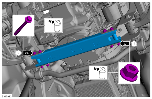
Remove and discard the front crossmember nuts.
Torque: 76 lb.ft (103 Nm)
-
Remove and discard the bolts and remove the front crossmember.
-
Remove and discard the front crossmember nuts.
 |
Installation
-
To install, reverse the removal procedure.
 Front Bumper Bracket. Removal and Installation
Special Tool(s) /
General Equipment
Grinder
MIG/MAG Welding Equipment
Locking Pliers
Removal
WARNING:
Frame rail crush zones absorb crash energy during a
collision and must be replaced if damaged...
 Front Lower Control Arm Bracket. Removal and Installation
Special Tool(s) /
General Equipment
Grinder
8 mm Drill Bit
MIG/MAG Welding Equipment
Locking Pliers
Removal
Restore the vehicle to manufacturer's dimensions if required...
Other information:
Lincoln Navigator 2018-2026 Workshop Manual: Steering Column Tilt Motor. Removal and Installation
Removal NOTE: Removal steps in this procedure may contain installation details. Remove the steering column. Refer to: Steering Column (211-04 Steering Column, Removal and Installation). Remove the tilt motor retainers...
Lincoln Navigator 2018-2026 Workshop Manual: Pump Assembly. Description and Operation
Overview Item Description 1 Transmission fluid pump drive gear 2 Transmission fluid pump idler gear 3 Transmission fluid pump assembly 4 Transmission fluid filter The transmission fluid in the sump area at the bottom of the transm..
Categories
- Manuals Home
- 4th Gen Lincoln Navigator Service Manual (2018 - 2026)
- Power Running Board (PRB). Diagnosis and Testing
- Rear Bumper. Removal and Installation
- Transmission Fluid Drain and Refill. General Procedures
- Telematics Control Unit (TCU) Module. Removal and Installation
- Identification Codes. Description and Operation
Rear Stabilizer Bar Link. Removal and Installation
Removal
NOTE: Removal steps in this procedure may contain installation details.
With the vehicle in NEUTRAL, position it on a hoist.Refer to: Jacking and Lifting (100-02 Jacking and Lifting, Description and Operation).
NOTE: Use the hex-holding feature to prevent the stud from turning while removing the nut.
Remove and discard the 2 rear stabilizer bar link nuts and remove the rear stabilizer bar link.Torque: 46 lb.ft (63 Nm)
