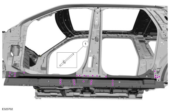
Lincoln Navigator: Rear End Sheet Metal Repairs / Front Floor Panel Side Member. Removal and Installation
Special Tool(s) / General Equipment
| 6.5 mm Drill Bit | |
| Scraper for Straight Edges | |
| Rivet Gun | |
| Self-Piercing Rivet (SPR) Remover/Installer | |
| Belt Sander | |
| Hot Air Gun | |
| Locking Pliers |
Materials
| Name | Specification |
|---|---|
| Metal Bonding Adhesive TA-1, TA-1-B, 3M™ 08115, LORD Fusor® 108B, Henkel Teroson EP 5055 |
- |
| Seam Sealer TA-2-B, 3M™ 08308, LORD Fusor® 803DTM |
- |
Removal
NOTICE: Panel sectioning is prohibited within 50 mm of door hinge, door striker, restraints and suspension anchoring points.
NOTE: Self-piercing rivet (SPR) fasteners may not be placed directly over original self-piercing rivet (SPR) location. They must be placed adjacent to original location matching original quantity.
NOTE: Aluminum body panels are highly receptive to heat transfer. With the extensive use of structural adhesives and non-structural sealers used in vehicle construction, the potential of heat transfer could impact adhesives and sealers in non-associated panels during the repair process. Many repair areas the utilize structural adhesive may be separated after fastener removal by using a panel chisel along the joint/flange. Using heat not exceeding 425° to loosen a bonded panel should only be done when all panels in the joint will be replaced and new adhesive applied.
NOTE: The front floor panel side panel may be sectioned providing the sectioning guidelines are adhered to. The following procedure assumes full component replacement. Adjust to meet repair needs.
NOTE: Left hand (LH) side shown, right hand (RH) side similar.
NOTE: Flow drill screws (FDS) are not reused. Remove and discard.
NOTE: Long wheelbase shown, short wheelbase similar.
-
Depower the SRS .
Refer to: Supplemental Restraint System (SRS) Depowering (501-20B Supplemental Restraint System, General Procedures).
-
If Necessary:
Dimensionally restore the vehicle to pre-damage condition.
Refer to: Body and Frame (501-26 Body Repairs - Vehicle Specific Information and Tolerance Checks, Description and Operation).
-
Remove the A, B and C-pillar trim.
Refer to: A-Pillar Trim Panel (501-05 Interior Trim and Ornamentation, Removal and Installation).
Refer to: B-Pillar Trim Panel (501-05 Interior Trim and Ornamentation, Removal and Installation).
Refer to: C-Pillar Trim Panel (501-05 Interior Trim and Ornamentation, Removal and Installation).
-
Remove the front and second row seats.
Refer to: Front Seat (501-10A Front Seats, Removal and Installation).
Refer to: Second Row Seat (501-10B Second Row Seats, Removal and Installation).
-
Position the carpet, electrical modules and wiring harnesses away from the working area.
-
Remove the A-pillar reinforcement.
Refer to: A-Pillar Outer Panel Section and Reinforcement (501-29 Side Panel Sheet Metal Repairs, Removal and Installation).
-
Remove the rocker panel reinforcement.
Refer to: Rocker Panel Inner Reinforcement (501-29 Side Panel Sheet Metal Repairs, Removal and Installation).
-
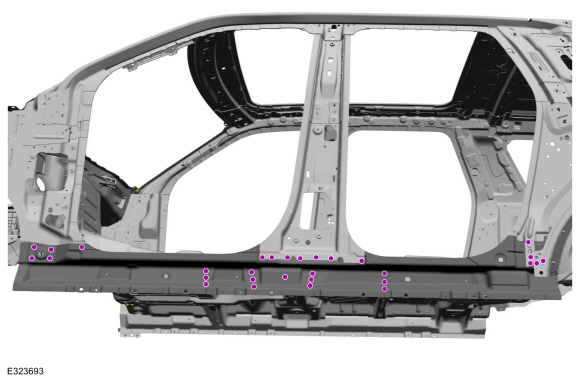
Remove the fasteners.
Use the General Equipment: Self-Piercing Rivet (SPR) Remover/Installer
Use the General Equipment: Belt Sander
 |
-
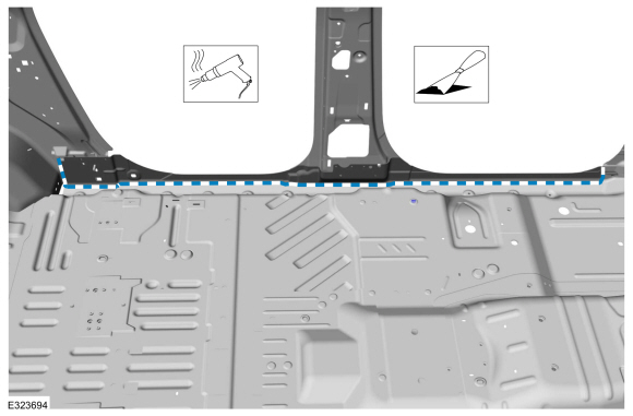
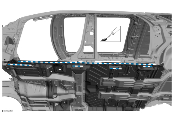
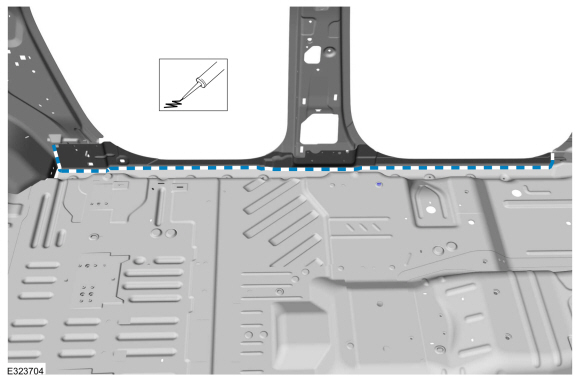
Remove the seam sealer.
Use the General Equipment: Hot Air Gun
Use the General Equipment: Scraper for Straight Edges
 |
-
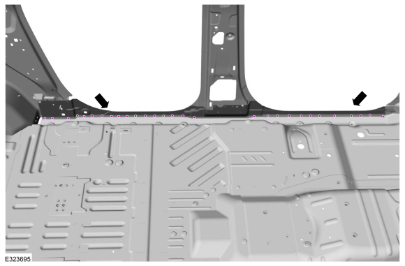
Remove the fasteners.
Use the General Equipment: Self-Piercing Rivet (SPR) Remover/Installer
Use the General Equipment: Belt Sander
 |
-
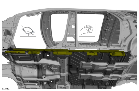
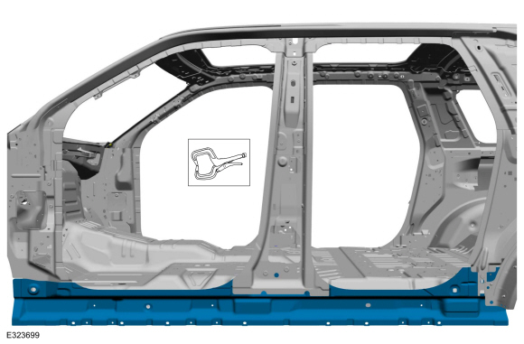
Break the adhesive bond and remove the front floor side panel reinforcement.
Use the General Equipment: Hot Air Gun
 |
Installation
NOTICE: Panel sectioning is prohibited within 50 mm of door hinge, door striker, restraints and suspension anchoring points.
NOTE: Self-piercing rivet (SPR) fasteners may not be placed directly over original self-piercing rivet (SPR) location. They must be placed adjacent to original location matching original quantity.
NOTE: Aluminum body panels are highly receptive to heat transfer. With the extensive use of structural adhesives and non-structural sealers used in vehicle construction, the potential of heat transfer could impact adhesives and sealers in non-associated panels during the repair process. Many repair areas the utilize structural adhesive may be separated after fastener removal by using a panel chisel along the joint/flange. Using heat not exceeding 425° to loosen a bonded panel should only be done when all panels in the joint will be replaced and new adhesive applied.
NOTE: The front floor panel side panel may be sectioned providing the sectioning guidelines are adhered to. The following procedure assumes full component replacement. Adjust to meet repair needs.
NOTE: Left hand (LH) side shown, right hand (RH) side similar.
NOTE: Long wheelbase shown, short wheelbase similar.
-
80-120 Grit Sand Paper:
Sand to remove old adhesive, e-coat and clean.
 |
-
Apply adhesive.
Material: Metal Bonding Adhesive / TA-1, TA-1-B, 3M™ 08115, LORD Fusor® 108B, Henkel Teroson EP 5055
 |
-
Install, properly position and clamp the reinforcement.
Use the General Equipment: Locking Pliers
 |
-
Drill for fasteners.
Use the General Equipment: 6.5 mm Drill Bit
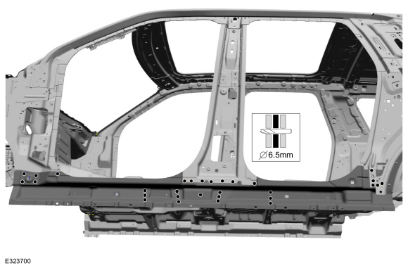 |
-
Drill for fasteners.
Use the General Equipment: 6.5 mm Drill Bit
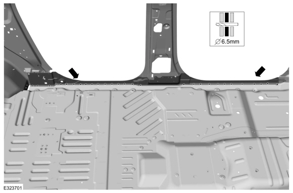 |
-
Install the fasteners.
Use the General Equipment: Rivet GunItem SPR Number SPR Code Henrob®, Car-O-Liner ®, CMO®, Chief®, Spanesi®, Wielander and Schill® Mandrel Pro- Spot ® Mandrel Blind Rivet Solid Rivet Rivnut® 1 - - - - W708777-S900C - -
 |
-
Install the fasteners.
Use the General Equipment: Rivet GunItem SPR Number SPR Code Henrob®, Car-O-Liner ®, CMO®, Chief®, Spanesi®, Wielander and Schill® Mandrel Pro- Spot ® Mandrel Blind Rivet Solid Rivet Rivnut® 1 - - - - W702512-S900C - -
 |
-
Seam Sealing:
All seams must be sealed to production level.
Material: Seam Sealer / TA-2-B, 3M™ 08308, LORD Fusor® 803DTM
 |
-
Install the rocker panel reinforcement.
Refer to: Rocker Panel Inner Reinforcement (501-29 Side Panel Sheet Metal Repairs, Removal and Installation).
-
Install the A-pillar reinforcement.
Refer to: A-Pillar Outer Panel Section and Reinforcement (501-29 Side Panel Sheet Metal Repairs, Removal and Installation).
-
Refinish the entire repair using a Ford approved paint system.
-
Restore corrosion protection.
Refer to: Corrosion Prevention (501-25 Body Repairs - General Information, General Procedures).
-
Position all wiring harnesses, electrical modules and the carpet to original location.
-
Install the front and second row seats.
Refer to: Second Row Seat (501-10B Second Row Seats, Removal and Installation).
Refer to: Front Seat (501-10A Front Seats, Removal and Installation).
-
Install the C, B and A-pillar trim.
Refer to: C-Pillar Trim Panel (501-05 Interior Trim and Ornamentation, Removal and Installation).
Refer to: B-Pillar Trim Panel (501-05 Interior Trim and Ornamentation, Removal and Installation).
Refer to: A-Pillar Trim Panel (501-05 Interior Trim and Ornamentation, Removal and Installation).
-
Repower the SRS .
Refer to: Supplemental Restraint System (SRS) Repowering (501-20B Supplemental Restraint System, General Procedures).

 Inner Quarter Panel. Removal and Installation
Special Tool(s) /
General Equipment
6.5 mm Drill Bit
Spherical Cutter
Polydrive Bit Socket
Rivet Gun
Self-Piercing Rivet (SPR) Remover/Installer
Belt Sander
Blind Rivet Gun
Air Body Saw
Locking Pliers
Materials
Name
Specification
Metal Bonding AdhesiveTA-1, TA-1-B, 3M™ 08115, LORD Fusor® 108B, Henkel..
Other information:
Lincoln Navigator 2018-2026 Workshop Manual: Drilling Precautions. General Procedures
Activation If a hole must be drilled in the frame the following requirements must be followed: The hole is at least the specified distance from the edge of the nearest hole. The edge of the drilled hole is at least the specified distance from the edge of the flange. The hole is at least the specified distance above the frame centerline. ..
Lincoln Navigator 2018-2026 Workshop Manual: Azimuth System Check. General Procedures
Check NOTE: The object used in this system check can be fabricated using a 9 cm diameter (3 in I.D.) pipe, 100 cm (39 in) in length (available as Polyvinyl Chloride (PVC) pipe, or similar from a hardware or plumbing supply. NOTE: The following system check should be carried out with the vehicle on a level surface. NOTE: Actual sensor arrangement may differ fr..
Categories
- Manuals Home
- 4th Gen Lincoln Navigator Service Manual (2018 - 2026)
- Front Seat. Removal and Installation
- Body Control Module (BCM). Removal and Installation
- Body and Paint
- Transmission Fluid Drain and Refill. General Procedures
- Rear Bumper. Removal and Installation
Rear Stabilizer Bar Link. Removal and Installation
Removal
NOTE: Removal steps in this procedure may contain installation details.
With the vehicle in NEUTRAL, position it on a hoist.Refer to: Jacking and Lifting (100-02 Jacking and Lifting, Description and Operation).
NOTE: Use the hex-holding feature to prevent the stud from turning while removing the nut.
Remove and discard the 2 rear stabilizer bar link nuts and remove the rear stabilizer bar link.Torque: 46 lb.ft (63 Nm)
