Lincoln Navigator: Full Frame and Body Mounting / Frame Members-Front Frame Section. Removal and Installation
Special Tool(s) / General Equipment
| Grinder | |
| Plasma Cutter | |
| MIG/MAG Welding Equipment | |
| Locking Pliers |
Removal
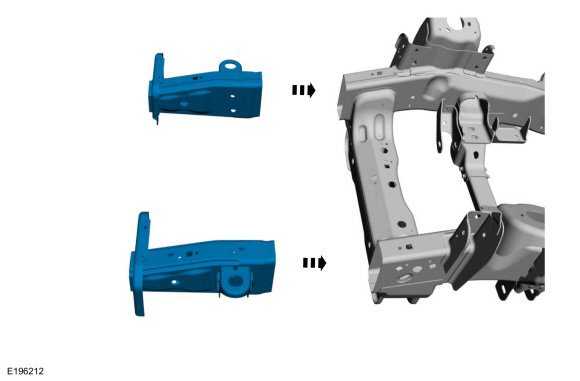
NOTE: The following procedure provides steps to replace the front frame short section at the first frame crossmember or the frame section at the center rail joint depending on the extent of vehicle damage.
-
Restore the vehicle to manufacturer's dimensions.
Refer to: Body and Frame (501-26 Body Repairs - Vehicle Specific Information and Tolerance Checks, Description and Operation).
All vehicles
-
Remove the following items:
-
Refer to: Front Bumper (501-19 Bumpers, Removal and Installation).
-
Refer to: Fender (501-02 Front End Body Panels, Removal and Installation).
-
Unbolt the Front End Sheet Metal (FESM) body mount bolts and raise or remove the body if required.
Refer to: Frame and Body Mounting (502-02 Full Frame and Body Mounting, Description and Operation).
-
Refer to: Front Bumper (501-19 Bumpers, Removal and Installation).
- Anchor the vehicle to a frame rack following the equipment manufacturer's instructions.
Front Frame Short Section
NOTICE: This section of the frame MUST NOT be straightened if any holes or surfaces show evidence of collapse or buckling. If any evidence of damage exists BEHIND the first frame cross member in terms of buckling, cracking, etc. then the entire front frame section or entire frame must be replaced.
-
NOTE: The replacement front frame components are production parts designed with a taper to insert into the front rail section to assist in alignment and welding operations.
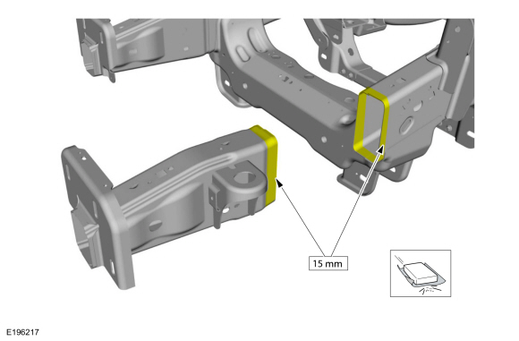
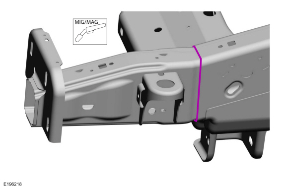
Front frame short section overview.
 |
-
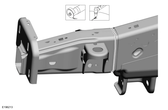
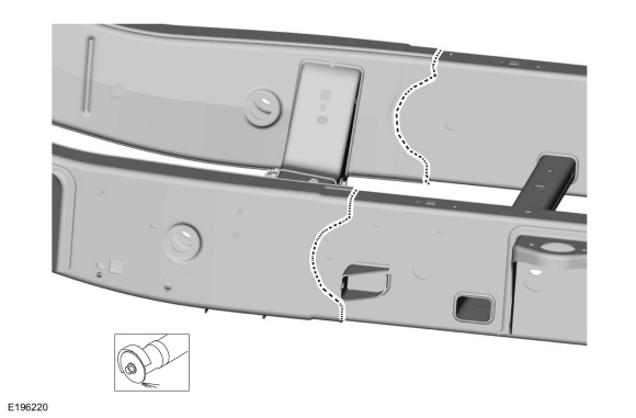
NOTICE: Do not cut directly along the center of the weld line. Leave enough material on the front side of the weld centerline to allow the remaining weld and frame material to be ground back to the front edge of the front mid rail. This is necessary to make sure of correct fit between the frame and the replacement frame section.
NOTE: LH side shown, RH side similar.
Locate the vertical weld of the front frame to center rail, using a plasma cutter, reciprocating saw or cut-off wheel cut through the frame rail.
Use the General Equipment: Grinder
Use the General Equipment: Plasma Cutter
 |
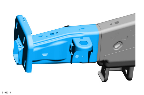
-
Remove the frame section from the affected side.
 |
-
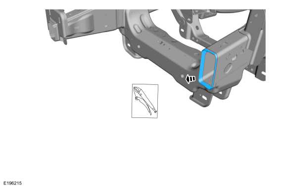
NOTICE: Do not thin out the frame rail. The material must maintain a minimum thickness of 3.1 mm (0.12 in) after grinding. This is required to maintain correct energy management in the event of a collision.
Grind off the excess welding material that remains around the perimeter of the front edge of the front frame rail of the frame assembly, and remove the remaining portion of the frame section from inside the frame rail.
Use the General Equipment: Locking Pliers
 |
-
Using a wire brush or sandpaper, remove the e-coat
paint from the existing frame near the edges to be welded on the inner
and outer surfaces within approximately 15 mm (0.5 in.) of the repair
joint.
 |
Front Frame Section
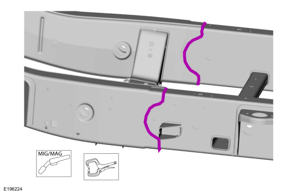
NOTE: The front frame section on this vehicle is retained by welded lap joints. The frame section will be removed and installed by grinding of the original welded joints, followed by welding of the new section into position.
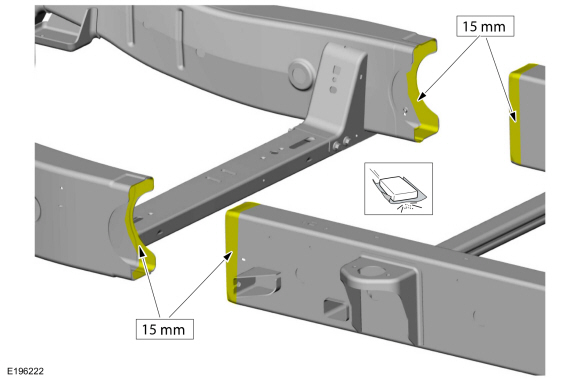
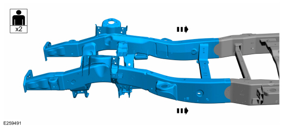
- Front frame section overview.
 |
-
Remove the following items:
-
Refer to: Transmission Support Crossmember (502-02 Full Frame and Body Mounting, Removal and Installation).
-
If equipped.
Refer to: Front Driveshaft (205-01 Driveshaft, Removal and Installation).
-
If equipped.
-
Refer to: Shock Absorber and Spring Assembly (204-01B Front Suspension - LHD 4WD, Removal and Installation).
Refer to: Shock Absorber and Spring Assembly (204-01A Front Suspension - LHD RWD, Removal and Installation).
-
Raise and support the engine and transmission assembly.
Refer to: Engine Mount RH (303-01 Engine - 3.5L EcoBoost (272kW/370PS), Removal and Installation).
Refer to: Engine Mount LH (303-01 Engine - 3.5L EcoBoost (272kW/370PS), Removal and Installation).
-
Remove the lower control arm, if equipped with 2WD .
Refer to: Lower Arm (204-01A Front Suspension - LHD RWD, Removal and Installation).
-
Remove the lower control arm, if equipped with 4WD .
Refer to: Lower Arm (204-01B Front Suspension - LHD 4WD, Removal and Installation).
-
Remove the upper control arm, if equipped with 2WD .
Refer to: Upper Arm (204-01A Front Suspension - LHD RWD, Removal and Installation).
-
Remove the upper control arm, if equipped with 4WD .
Refer to: Upper Arm (204-01B Front Suspension - LHD 4WD, Removal and Installation).
-
Refer to: Steering Gear (211-02 Power Steering, Removal and Installation).
-
Disconnect the exhaust system for the engine.
Refer to: Catalytic Converter RH (309-00 Exhaust System - 3.5L EcoBoost (272kW/370PS), Removal and Installation).
Refer to: Catalytic Converter LH (309-00 Exhaust System - 3.5L EcoBoost (272kW/370PS), Removal and Installation).
-
Refer to: Transmission Support Crossmember (502-02 Full Frame and Body Mounting, Removal and Installation).
- Loosen the body mount to frame bushing bolts from the radiator support and the forward cab support.
- Disconnect and remove any remaining wiring, lines, and related fittings from the frame section.
-
Grind through the original welded joints retaining the forward frame section to the center section. Be careful not to cut into the center side rail since it will be reused.
-
Using a chisel gun with a sharp 25.4 mm (1 inch)
wide wedge chisel, separate the ground area of the joints.
Use the General Equipment: Grinder
-
Using a chisel gun with a sharp 25.4 mm (1 inch)
wide wedge chisel, separate the ground area of the joints.
 |
-
With the help of an assistant, remove the complete front frame section.
 |
-
NOTICE: Do not thin out the frame rail. The material must maintain a minimum thickness of 3.1 mm (0.12 in) after grinding. This is required to maintain correct energy management in the event of a collision.
Grind off the excess welding material that remains around the perimeter of the front edge of the mid frame rail of the frame assembly, and remove the remaining portion of the frame section from inside the frame rail.
-
Using a wire brush or sandpaper, remove the e-coat
paint from the existing frame near the edges to be welded on the inner
and outer surfaces within approximately 15 mm (0.5 in.) of the repair
joint.
 |
Installation
Front Frame Short Section
NOTE: LH side shown, RH side similar.
-
Verify dimensional accuracy before performing any welding operations.
Refer to: Body and Frame (501-26 Body Repairs - Vehicle Specific Information and Tolerance Checks, Description and Operation).
-
NOTE: Check that the Front End Sheet Metal (FESM) body mount bracket lines up with the sheet metal hole for the body mount bolt.
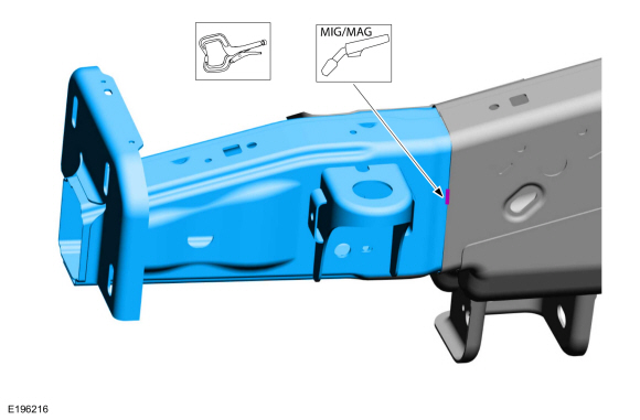
Install the front frame section inside the mid front rail of the frame and tack weld at 4 locations.
Refer to: Joining Techniques (501-25 Body Repairs - General Information, General Procedures).
Use the General Equipment: MIG/MAG Welding Equipment
Use the General Equipment: Locking Pliers
 |
-
Re-check the frame replacement alignment by lowering
the body, and then raise it. Weld the joint completely if this
alignment is correct.
Use the General Equipment: MIG/MAG Welding Equipment
 |
- Metal finish the repair area using typical metal finishing techniques.
- Refinish using a Ford approved paint system.
-
Restore corrosion protection.
Refer to: Corrosion Prevention (501-25 Body Repairs - General Information, General Procedures).
Front Frame Section
-
With the help of an assistant, position the new front frame section into place on the vehicle.
 |
-
Verify dimensional accuracy before performing any welding operations.
Refer to: Body and Frame (501-26 Body Repairs - Vehicle Specific Information and Tolerance Checks, Description and Operation).
-
Support the new section, and loosely clamp the replacement section in a preliminary position.
-
Verify correct dimensions, then solid weld the new section to the original on all overlap joints.
Refer to: Joining Techniques (501-25 Body Repairs - General Information, General Procedures).
Refer to: Body and Frame (501-26 Body Repairs - Vehicle Specific Information and Tolerance Checks, Description and Operation).
Use the General Equipment: MIG/MAG Welding Equipment
Use the General Equipment: Locking Pliers
-
Verify correct dimensions, then solid weld the new section to the original on all overlap joints.
 |
- Metal finish the repair area using typical metal finishing techniques.
- Refinish using a Ford approved paint system.
-
Restore corrosion protection.
Refer to: Corrosion Prevention (501-25 Body Repairs - General Information, General Procedures).
-
Install the following items:
-
Refer to: Transmission Support Crossmember (502-02 Full Frame and Body Mounting, Removal and Installation).
-
If equipped.
Refer to: Front Driveshaft (205-01 Driveshaft, Removal and Installation).
-
If equipped.
-
Refer to: Shock Absorber and Spring Assembly (204-01B Front Suspension - LHD 4WD, Removal and Installation).
Refer to: Shock Absorber and Spring Assembly (204-01A Front Suspension - LHD RWD, Removal and Installation).
-
Install the lower control arm, if equipped with 2WD .
Refer to: Lower Arm (204-01A Front Suspension - LHD RWD, Removal and Installation).
-
Install the lower control arm, if equipped with 4WD .
Refer to: Lower Arm (204-01B Front Suspension - LHD 4WD, Removal and Installation).
-
Install the upper control arm, if equipped with 2WD .
Refer to: Upper Arm (204-01A Front Suspension - LHD RWD, Removal and Installation).
-
Install the upper control arm, if equipped with 4WD .
Refer to: Upper Arm (204-01B Front Suspension - LHD 4WD, Removal and Installation).
-
Refer to: Steering Gear (211-02 Power Steering, Removal and Installation).
-
Reposition the engine and transmission assembly.
Refer to: Engine Mount RH (303-01 Engine - 3.5L EcoBoost (272kW/370PS), Removal and Installation).
Refer to: Engine Mount LH (303-01 Engine - 3.5L EcoBoost (272kW/370PS), Removal and Installation).
-
Reconnect the exhaust system to the engine.
Refer to: Catalytic Converter RH (309-00 Exhaust System - 3.5L EcoBoost (272kW/370PS), Removal and Installation).
Refer to: Catalytic Converter LH (309-00 Exhaust System - 3.5L EcoBoost (272kW/370PS), Removal and Installation).
-
Refer to: Transmission Support Crossmember (502-02 Full Frame and Body Mounting, Removal and Installation).
All vehicles
-
Install the following items:
-
Refer to: Front Bumper (501-19 Bumpers, Removal and Installation).
-
Refer to: Fender (501-02 Front End Body Panels, Removal and Installation).
-
Refer to: Front Bumper (501-19 Bumpers, Removal and Installation).
 Driveshaft Center Bearing Bracket. Removal and Installation
Special Tool(s) /
General Equipment
Grinder
MIG/MAG Welding Equipment
Locking Pliers
Removal
NOTE:
The following applies to left hand (LH) drive/rear wheel drive (RWD) vehicles only...
 Frame Members-Rear Frame Section. Removal and Installation
Special Tool(s) /
General Equipment
Grinder
MIG/MAG Welding Equipment
Removal
Restore the vehicle to manufacturer's dimensions...
Other information:
Lincoln Navigator 2018-2026 Workshop Manual: Steering Column Control Module (SCCM). Removal and Installation
Removal NOTE: Removal steps in this procedure may contain installation details. NOTE: This step is only necessary when installing a new component. NOTE: The PMI process must begin with the current SCCM installed. If the current SCCM does not respond to the diagnostic scan tool, the tool may prompt for As-Built data as part of the repair...
Lincoln Navigator 2018-2026 Workshop Manual: Front Lower Control Arm Bracket. Removal and Installation
Special Tool(s) / General Equipment Grinder 8 mm Drill Bit MIG/MAG Welding Equipment Locking Pliers Removal Restore the vehicle to manufacturer's dimensions if required. Refer to: Body and Frame (501-26 Body Repairs - Vehicle Specific Information and Tolerance Checks, Description and Operation)...
Categories
- Manuals Home
- 4th Gen Lincoln Navigator Service Manual (2018 - 2026)
- Body Control Module (BCM). Removal and Installation
- Head Up Display (HUD) Module Calibration. General Procedures
- Front Bumper Cover. Removal and Installation
- Body and Paint
- Rear View Mirrors - System Operation and Component Description. Description and Operation
Rear Drive Axle and Differential. Diagnosis and Testing
Symptom Chart(s)
Diagnostics in this manual assume a certain skill level and knowledge of Ford-specific diagnostic practices.
REFER to: Diagnostic Methods (100-00 General Information, Description and Operation).
Symptom Chart - Differential
Symptom Chart - Differential
Condition Actions Axle overheating GO to Pinpoint Test A Broken gear teeth on the ring gear or pinion GO to Pi