Lincoln Navigator: Full Frame and Body Mounting / Frame Members-Rear Frame Section. Removal and Installation
Special Tool(s) / General Equipment
| Grinder | |
| MIG/MAG Welding Equipment |
Removal
-
Restore the vehicle to manufacturer's dimensions.
Refer to: Body and Frame (501-26 Body Repairs - Vehicle Specific Information and Tolerance Checks, Description and Operation).
-
Remove the following items:
-
Refer to: Rear Bumper (501-19 Bumpers, Removal and Installation).
-
As equipped.
Refer to: Muffler and Tailpipe (309-00 Exhaust System - 3.5L EcoBoost (272kW/370PS), Removal and Installation).
-
As equipped.
Refer to: Fuel Tank Filler Pipe (310-01 Fuel Tank and Lines - 3.5L EcoBoost (272kW/370PS), Removal and Installation).
-
Refer to: Shock Absorber and Spring Assembly (204-02 Rear Suspension, Removal and Installation).
-
Remove the spare wheel.
Refer to: Frame and Body Mounting (502-02 Full Frame and Body Mounting, Description and Operation).
-
Unbolt the Front End Sheet Metal (FESM) body mount bolts and raise or remove the body if required.
Refer to: Frame and Body Mounting (502-02 Full Frame and Body Mounting, Description and Operation).
-
Refer to: Rear Bumper (501-19 Bumpers, Removal and Installation).
-
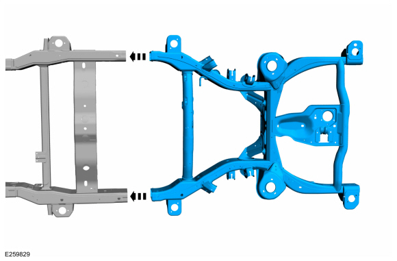
Rear frame section overview.
 |
-
Position the vehicle on a frame rack and anchor per manufacturer's instructions.
-
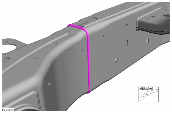
NOTICE: Do not cut directly along the center of the weld line. Leave enough material on the front side of the weld centerline to allow the remaining weld and frame material to be ground back to the front edge of the front mid rail. This is necessary to make sure of correct fit between the frame and the replacement frame section.
NOTE: Use caution not cut into the mid rear side rail as it will be reused.
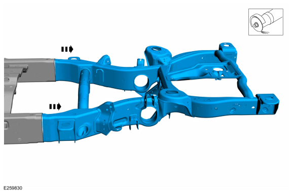
Using a plasma cutter, reciprocating saw or die-grinder, remove the damaged rear frame section.
-
Separate the ground area of the joints using an air
chisel or similar tool and remove the complete rear frame section.
Use the General Equipment: Grinder
-
Separate the ground area of the joints using an air
chisel or similar tool and remove the complete rear frame section.
 |
-
NOTICE: Do not thin out the frame rail. The material must maintain a minimum thickness of 3.1 mm (0.12 in) after grinding. This is required to maintain correct energy management in the event of a collision.
Grind off the excess welding material that remains in rear of the weld line on the frame mid-rail.
Installation
-
Refer to: Joining Techniques (501-25 Body Repairs - General Information, General Procedures).
-
NOTE: Verify dimensional accuracy before performing any welding operations.
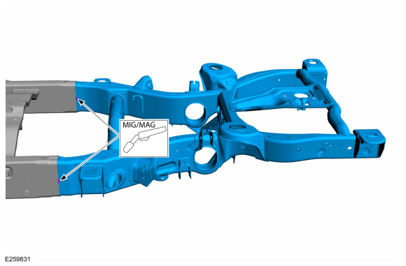
Install the new rear frame section into the mid rear section of the frame and tack weld the frame rails.
Refer to: Body and Frame (501-26 Body Repairs - Vehicle Specific Information and Tolerance Checks, Description and Operation).
 |
-
Perform a final measurement, then final weld the new
rear section to the mid rear section on all overlap joints on both
sides.
Use the General Equipment: MIG/MAG Welding Equipment
 |
-
Metal finish the joint area typical metal finishing techniques.
-
Metal finish the joint area typical metal finishing techniques.
-
Refinish using a Ford approved paint system.
-
Restore corrosion protection.
Refer to: Corrosion Prevention (501-25 Body Repairs - General Information, General Procedures).
-
NOTICE: To avoid damage to the spare tire winch when installing the spare tire, DO NOT exceed 200 RPM if using power tool equipment.
Install the following items:-
As equipped.
Refer to: Fuel Tank Filler Pipe (310-01 Fuel Tank and Lines - 3.5L EcoBoost (272kW/370PS), Removal and Installation).
-
As equipped.
Refer to: Muffler and Tailpipe (309-00 Exhaust System - 3.5L EcoBoost (272kW/370PS), Removal and Installation).
-
Refer to: Shock Absorber and Spring Assembly (204-02 Rear Suspension, Removal and Installation).
-
Refer to: Rear Bumper (501-19 Bumpers, Removal and Installation).
-
As equipped.
 Frame Members-Front Frame Section. Removal and Installation
Special Tool(s) /
General Equipment
Grinder
Plasma Cutter
MIG/MAG Welding Equipment
Locking Pliers
Removal
NOTE:
The following procedure provides steps to replace the front
frame short section at the first frame crossmember or the frame section
at the center rail joint depending on the extent of vehicle damage...
 Front Bumper Bracket. Removal and Installation
Special Tool(s) /
General Equipment
Grinder
MIG/MAG Welding Equipment
Locking Pliers
Removal
WARNING:
Frame rail crush zones absorb crash energy during a
collision and must be replaced if damaged...
Other information:
Lincoln Navigator 2018-2026 Workshop Manual: Roof Rear Frame. Removal and Installation
Special Tool(s) / General Equipment 6.5 mm Drill Bit Self-Piercing Rivet (SPR) Remover/Installer Belt Sander Blind Rivet Gun Locking Pliers Materials Name Specification Metal Bonding AdhesiveTA-1, TA-1-B, 3M™ 08115, LORD Fusor® 108B, Henkel Teroson EP 5055 - Seam SealerTA-2-B, 3M™ 08308, LORD Fusor® 803DTM -..
Lincoln Navigator 2018-2026 Workshop Manual: Front Door Upper Moulding. Removal and Installation
Removal NOTE: Removal steps in this procedure may contain installation details. NOTE: LH side shown, RH side similar. All vehicles Lower the door window glass completely. Remove the exterior mirror. Refer to: Exterior Mirror (501-09 Rear View Mirrors, Removal and Installation). Remove..
Categories
- Manuals Home
- 4th Gen Lincoln Navigator Service Manual (2018 - 2026)
- Identification Codes. Description and Operation
- Power Running Board (PRB). Diagnosis and Testing
- Brake Service Mode Activation and Deactivation. General Procedures
- Front Seat. Removal and Installation
- Telematics Control Unit (TCU) Module. Removal and Installation
Wheel to Hub Runout Minimization. General Procedures
Check
NOTE: Wheel-to-hub optimization is important. Clearance between the wheel and hub can be used to offset or neutralize the Road Force® or run-out of the wheel and tire assembly. For every 0.001 inch of wheel-to-hub clearance, the Road Force® can be affected between 1 and 3 pounds depending on the tire stiffness.
NOTE: The example below illustrates how the clearance between the wheel and the hub can be used to offset the high spot of radial run-out or Road Force®. Following the procedure will make sure of the best optimization.
Position the wheel and tire assembly on the vehicle so that the high spot location of radial run-out or Road Force® is at the 6 o'clock position and