Lincoln Navigator: Full Frame and Body Mounting / Driveshaft Center Bearing Bracket. Removal and Installation
Special Tool(s) / General Equipment
| Grinder | |
| MIG/MAG Welding Equipment | |
| Locking Pliers |
Removal
NOTE: The following applies to left hand (LH) drive/rear wheel drive (RWD) vehicles only.
-
Restore the vehicle to manufacturer's dimensions.
Refer to: Body and Frame (501-26 Body Repairs - Vehicle Specific Information and Tolerance Checks, Description and Operation).
-
Remove the following items:
-
Remove the rear driveshaft.
Refer to: Rear Driveshaft (205-01 Driveshaft, Removal and Installation).
-
Remove the fuel tank.
Refer to: Fuel Tank (310-01 Fuel Tank and Lines - 3.5L EcoBoost (272kW/370PS), Removal and Installation).
-
Remove the muffler.
Refer to: Muffler (309-00 Exhaust System - 3.5L EcoBoost (272kW/370PS), Removal and Installation).
-
Remove the rear driveshaft.
-
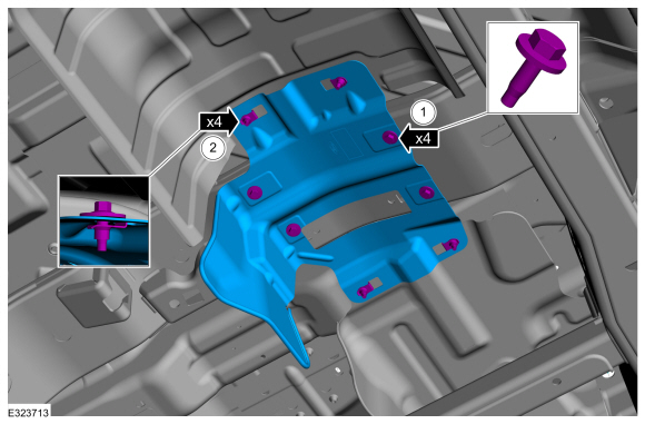
Remove the bolts and the heat shield.
 |
- Anchor the vehicle to a frame rack following the equipment manufacturer's instructions.
-
NOTE: Be careful not to cut into the frame cross member, it will be reused.
Grind the welds holding the driveshaft center bearing bracket to the frame and remove the driveshaft center bearing bracket.
Use the General Equipment: Grinder
 |
-
Clean the areas of the frame where the welds were ground.
 |
Installation
-
Refer to: Joining Techniques (501-25 Body Repairs - General Information, General Procedures).
-
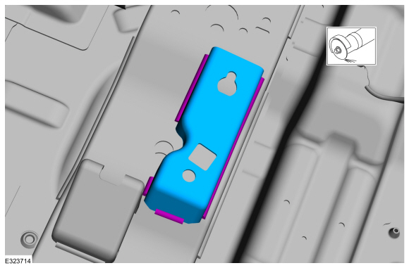
Loosely clamp the replacement bracket in a preliminary
position. Perform measurements to verify proper placement of the new
driveshaft center bearing bracket, then clamp firmly into position.
-
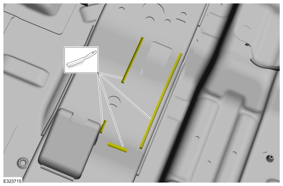
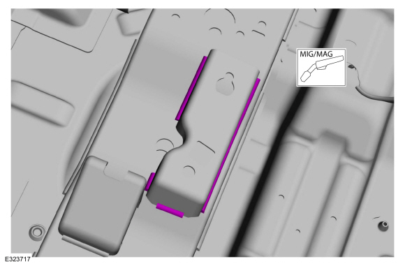
With all measurements verified and the new
driveshaft center bearing bracket in proper position, tack-weld the new
driveshaft center bearing bracket in place to the frame crossmember.
Use the General Equipment: Locking Pliers
Use the General Equipment: MIG/MAG Welding Equipment
-
With all measurements verified and the new
driveshaft center bearing bracket in proper position, tack-weld the new
driveshaft center bearing bracket in place to the frame crossmember.
 |
-
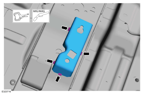
Re-check measurements, then solid weld the driveshaft center bearing bracket to the frame crossmember.
Use the General Equipment: MIG/MAG Welding Equipment
 |
-
Metal finish the repair area using typical metal finishing techniques.
-
Restore corrosion protection.
Refer to: Corrosion Prevention (501-25 Body Repairs - General Information, General Procedures).
-
Install the bolts and the heat shield.
Torque:
1: 177 lb.in (20 Nm)
2: 177 lb.in (20 Nm)
|
-
Install the muffler.
Refer to: Muffler (309-00 Exhaust System - 3.5L EcoBoost (272kW/370PS), Removal and Installation).
-
Install the fuel tank.
Refer to: Fuel Tank (310-01 Fuel Tank and Lines - 3.5L EcoBoost (272kW/370PS), Removal and Installation).
-
Install the rear driveshaft.
Refer to: Rear Driveshaft (205-01 Driveshaft, Removal and Installation).
 Drilling Precautions. General Procedures
Activation
If a hole must be drilled in the frame the following requirements must be followed:
The hole is at least the specified distance from the edge of the nearest hole...
 Frame Members-Front Frame Section. Removal and Installation
Special Tool(s) /
General Equipment
Grinder
Plasma Cutter
MIG/MAG Welding Equipment
Locking Pliers
Removal
NOTE:
The following procedure provides steps to replace the front
frame short section at the first frame crossmember or the frame section
at the center rail joint depending on the extent of vehicle damage...
Other information:
Lincoln Navigator 2018-2026 Workshop Manual: Rear Stabilizer Bar Link. Removal and Installation
Removal NOTE: Removal steps in this procedure may contain installation details. With the vehicle in NEUTRAL, position it on a hoist. Refer to: Jacking and Lifting (100-02 Jacking and Lifting, Description and Operation). NOTE: Use the hex-holding feature to prevent the stud from turning while removing the nut...
Lincoln Navigator 2018-2026 Workshop Manual: Axle Carrier Bushing. Removal and Installation
Special Tool(s) / General Equipment 204-186 (T95T-5638-AH) Remover, Front Differential Housing BushingTKIT-1995-FH/FLMHTKIT-1995-LMH/MH 204-187 (T95T-5638-BH) Installer, Front Differential Housing BushingTKIT-1995-FH/FLMHTKIT-1995-LMH/MH 205-289 (T89P-1249-A) Installer, Wheel Hub Dust SealTKIT-1988-FLMTKIT-1988-FTKIT-1989-LM 205-371 (T96T-..
Categories
- Manuals Home
- 4th Gen Lincoln Navigator Service Manual (2018 - 2026)
- Vehicle Dynamics Control Module (VDM). Removal and Installation
- Head Up Display (HUD) Module Calibration. General Procedures
- Body and Paint
- All Terrain Control Module (ATCM). Removal and Installation
- Transmission Fluid Drain and Refill. General Procedures
Front Stabilizer Bar Link. Removal and Installation
Removal
NOTICE: Suspension fasteners are critical parts that affect the performance of vital components and systems. Failure of these fasteners may result in major service expense. Use the same or equivalent parts if replacement is necessary. Do not use a replacement part of lesser quality or substitute design. Tighten fasteners as specified.
NOTE: Removal steps in this procedure may contain installation details.
With the vehicle in NEUTRAL, position it on a hoist.Refer to: Jacking and Lifting (100-02 Jacking and Lifting, Description and Operation).
NOTICE: Do not use power tools to remove or install the stabilizer bar