Lincoln Navigator: Roof Opening Panel / Roof Opening Panel - Overview. Description and Operation
Overview
The roof opening panel consists of the following:
- Air deflector
- Front sliding glass panel (sunroof)
- Front sliding glass panel motor (sunroof motor)
- Shield (sunshade) assembly
- Shield (sunshade) motor
- Blinds (concertina blinds)
- Roof panel fixed glass (panoramic)
- Roof opening panel frame assembly
- Roof opening panel drain hoses
- Roof opening panel control switch
- Shield (sunshade) switch rear
- Trough assembly
The
roof opening panel motor must be initialized when repairs are carried
out on the roof opening panel system, including: any time the roof
opening panel motor has been removed, the roof opening panel glass
(front sliding or fixed glass) has been removed or adjusted, or if the
roof opening panel frame has been removed.
Refer to: Power Roof Opening Panel Initialization (501-17 Roof Opening Panel, General Procedures).
The roof opening panel is an electronically operated glass panel that can be opened, closed or tilted (vent position) by the roof opening panel control switch and the vent switch. Actuating the switches supplies a signal to the roof opening panel motor/module. The front sliding glass panel and the shield (sunshade) use two integrated motors/modules that are serviced as assemblies. The roof opening panel has one-touch open and one-touch close features that are activated when the switch is pressed to the second detent on the glass open or close side of the switch (the sliding glass panel close switch acts as a vent switch when the glass is in the closed position). Additionally the shield (sunshade) switch has one-touch open feature that is activated when the switch is pressed to the second detent on the shield open side of the switch.
Vista Roof Panel Glass The roof opening panel system on this vehicle includes a fixed vista roof panel glass behind the front sliding glass panel. Any time this panel is removed or adjusted the front sliding glass panel will need to be initialized.
K Bus Communication There is a communication circuit (K Bus) between the roof opening panel motor and the shield motor that is only for communication between the motors and not for service diagnostics. If this circuit is opened or shorted the sunroof system will not operate. When the K Bus circuit is repaired, normal system function will return.
 Roof Opening Panel - System Operation and Component Description. Description and Operation
System Operation
Item
Description
1
BCM
2
Sliding Glass Motor
3
Roof Opening Panel Control Switch
4
Shield Motor
5
K Bus (not used for external communication)
Switch Operation
There are three switches located in the overhead console...
Other information:
Lincoln Navigator 2018-2026 Workshop Manual: Health and Safety Precautions. Description and Operation
General Service Warnings Review carefully the information below before beginning any repair. Following these warnings is a list of specific system warnings that must be reviewed before beginning work on any listed system. WARNING: Vehicles equipped with an automatic transmission and a Telematics Control Unit (TCU) have remote start technology and may start the eng..
Lincoln Navigator 2018-2026 Workshop Manual: Hood Latch. Removal and Installation
Removal NOTE: Removal steps in this procedure may contain installation details. Remove the pin-type retainers and position the air cleaner panel aside Release the clips and position the RH and LH cowl filler panels aside. Remove the pin-type retainers and the radiator sight shield. ..
Categories
- Manuals Home
- 4th Gen Lincoln Navigator Service Manual (2018 - 2026)
- Body Control Module (BCM). Removal and Installation
- Remote Function Actuator (RFA) Module. Removal and Installation
- Telematics Control Unit (TCU) Module. Removal and Installation
- Power Running Board (PRB). Diagnosis and Testing
- SYNC Module [APIM]. Removal and Installation
Rear Stabilizer Bar Link. Removal and Installation
Removal
NOTE: Removal steps in this procedure may contain installation details.
With the vehicle in NEUTRAL, position it on a hoist.Refer to: Jacking and Lifting (100-02 Jacking and Lifting, Description and Operation).
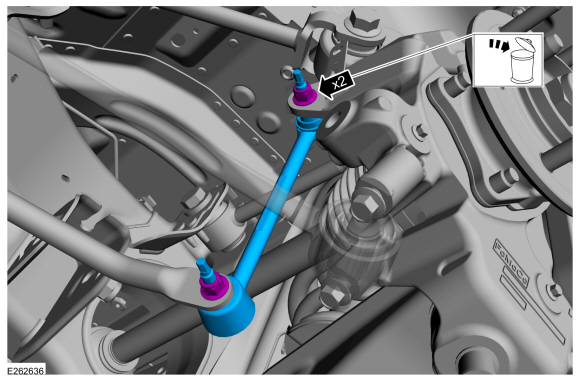
NOTE: Use the hex-holding feature to prevent the stud from turning while removing the nut.
Remove and discard the 2 rear stabilizer bar link nuts and remove the rear stabilizer bar link.Torque: 46 lb.ft (63 Nm)


