Lincoln Navigator: Front Drive Axle/Differential / Drive Pinion Flange and Seal. Removal and Installation
Special Tool(s) / General Equipment
 |
205-002
(TOOL-4858-E)
Installer, Drive Pinion Flange |
 |
205-126
(T78P-4851-A)
Holding Fixture, Drive Pinion Flange |
 |
205-208
(T83T-4676-A)
Installer, Drive Pinion Oil Seal TKIT-1983-F TKIT-1983-FLM TKIT-1983-FX |
 |
303-144
(T79T-6316-A)
Remover, Crankshaft Harmonic Balancer |
| Flat Headed Screw Driver | |
Materials
| Name | Specification |
|---|---|
| Motorcraft® SAE 75W-85 Premium Synthetic Hypoid Gear Lubricant XY-75W85-QL |
WSS-M2C942-A |
Removal
-
Remove the front brake pads.
Refer to: Brake Pads (206-03 Front Disc Brake, Removal and Installation).
-
Remove the front driveshaft.
Refer to: Front Driveshaft (205-01 Driveshaft, Removal and Installation).
-
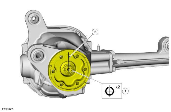
NOTE: Rotational torque of the drive pinion flange must be measured and recorded using a Nm (lb-in) torque wrench for correct pinion bearing preload when reassembled. This will be the torque-to-turn measurement.
-
Using a dial type torque wrench, measure and record the rotational torque of the drive pinion.
-
Index-mark the pinion flange and the drive pinion stem.
-
Using a dial type torque wrench, measure and record the rotational torque of the drive pinion.
 |
-
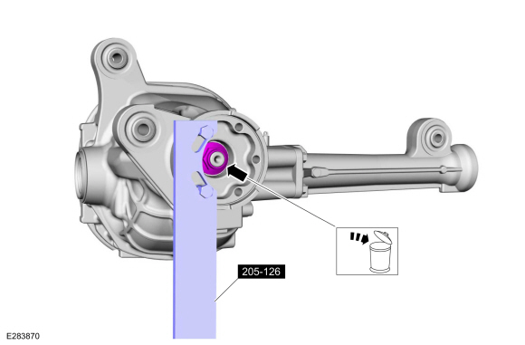
Using the special tool, remove and discard the pinion nut.
Use Special Service Tool: 205-126 (T78P-4851-A) Holding Fixture, Drive Pinion Flange.
 |
-
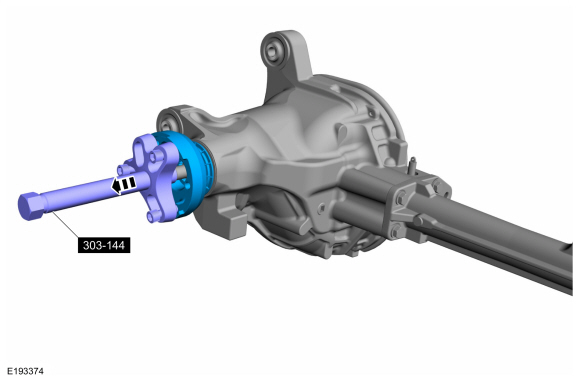
Using the special tool, remove the pinion flange.
Use Special Service Tool: 303-144 (T79T-6316-A) Remover, Crankshaft Harmonic Balancer.
 |
-
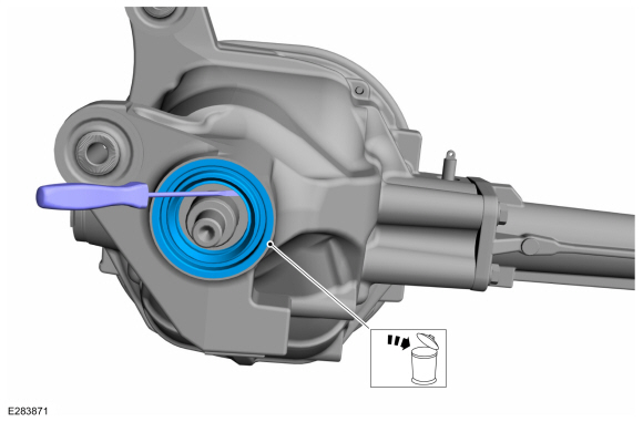
Using the general equipment, remove and discard the drive pinion seal.
Use the General Equipment: Flat Headed Screw Driver
 |
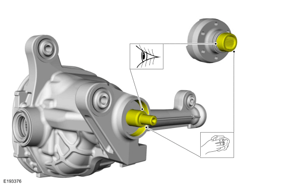
-
Clean and inspect the pinion flange mating surfaces and pinion seal surface.
 |
Installation
-
Using the special tool, install the new pinion seal.
Use Special Service Tool: 205-208 (T83T-4676-A) Installer, Drive Pinion Oil Seal.
 |
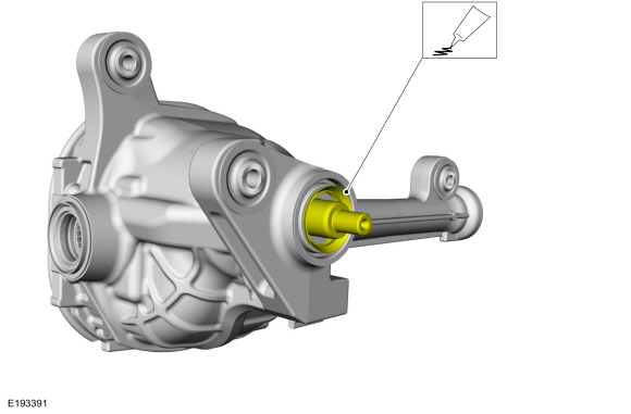
-
Lubricate the pinion seal and pinion splines.
Material: Motorcraft® SAE 75W-85 Premium Synthetic Hypoid Gear Lubricant / XY-75W85-QL (WSS-M2C942-A)
 |
-
NOTE: Make sure drive pinion flange and drive pinion stem are phased correctly using previously applied mark.
-
Align the index marks made during removal.
-
Using the special tool, install the pinion flange.
Use Special Service Tool: 205-002 (TOOL-4858-E) Installer, Drive Pinion Flange.
-
Align the index marks made during removal.
 |
-
NOTICE: Do not loosen the pinion nut to reduce drive pinion bearing preload. Install a new drive pinion collapsible spacer and pinion nut if drive pinion bearing preload reduction is necessary. If a new collapsible spacer must be installed for pinion bearing preload reduction, install the nut supplied with the new spacer or damage to the component may occur.
NOTE: Tighten the pinion nut, rotating the pinion occasionally to make sure the drive pinion bearings are seating correctly. Take frequent drive pinion bearing preload readings by rotating the drive pinion gear with a Nm (lb-in) torque wrench. The final reading must be 0.56 Nm (5 lb-in) more than the initial reading taken during removal.
NOTE: When installing the drive pinion flange and pinion nut with no differential carrier installed, the drag torque (torque to turn) should be 1.8 to 3.3 Nm (16-29 in-lbs).
Using the special tool, install the new pinion nut.
Use Special Service Tool: 205-126 (T78P-4851-A) Holding Fixture, Drive Pinion Flange.
 |
-
Check the front differential fluid level.
Refer to: Differential Fluid Level Check (205-03 Front Drive Axle/Differential, General Procedures).
-
Install the front driveshaft.
Refer to: Front Driveshaft (205-01 Driveshaft, Removal and Installation).
-
Install the front brake pads.
Refer to: Brake Pads (206-03 Front Disc Brake, Removal and Installation).

 Differential Carrier. Disassembly and Assembly
Special Tool(s) /
General Equipment
205-386
(T97T-4205-D)
Gauge, Differential (Traction Lock)TKIT-1998-LM (NavigatoR)TKIT-1997-F/FLM/LT
Hydraulic Press
Punch
Copper Hammer
Bearing Separator
Materials
Name
Specification
Motorcraft® SAE 75W-85 Premium Synthetic Hypoid Gear LubricantXY-75W85-QL
WSS-M2C942-A
D..
Other information:
Lincoln Navigator 2018-2026 Workshop Manual: Rear Drive Halfshafts. Diagnosis and Testing
Preliminary Inspection Visually inspect the CV joints, housing, boots, and clamps for obvious signs of mechanical damage. If an obvious cause for an observed or reported concern is found, correct the cause (if possible) before proceeding to the next step If the cause is not visually evident, verify the symptom and REFER to Symptom Chart: NVH. Sym..
Lincoln Navigator 2018-2026 Workshop Manual: Road Testing Vehicle. Diagnosis and Testing
Shift Point Road Test NOTE: Always drive the vehicle in a safe manner according to driving conditions and obey all traffic laws. Upshift Gear Sequence At times the 10-speed transmission may skip gears when the vehicle starts from a complete stop. This is normal and desired behavior. At part pedal when acceleration is brisk, single step upshifts would result in very fr..
Categories
- Manuals Home
- 4th Gen Lincoln Navigator Service Manual (2018 - 2026)
- Neutral Flat Tow Activation and Deactivation. General Procedures
- Windshield Washer Pump. Removal and Installation
- Telematics Control Unit (TCU) Module. Removal and Installation
- Liftgate Trim Panel. Removal and Installation
- SYNC Module [APIM]. Removal and Installation
Rear Drive Axle and Differential. Diagnosis and Testing
Symptom Chart(s)
Diagnostics in this manual assume a certain skill level and knowledge of Ford-specific diagnostic practices.
REFER to: Diagnostic Methods (100-00 General Information, Description and Operation).
Symptom Chart - Differential
Symptom Chart - Differential
Condition Actions Axle overheating GO to Pinpoint Test A Broken gear teeth on the ring gear or pinion GO to Pi