Lincoln Navigator: Front Drive Axle/Differential / Differential Bearings. Removal and Installation
Special Tool(s) / General Equipment
 |
100-002
(TOOL-4201-C)
Holding Fixture with Dial Indicator Gauge |
 |
205-001
(TOOL-4000-E)
Spreader, Differential Carrier |
 |
205-005
(T53T-4621-C)
Installer, Drive Pinion Bearing Cone |
 |
205-010
(T57L-4221-A2)
Installer, Differential Side Bearing |
 |
205-024
(T67P-4616-A)
Installer, Drive Pinion Bearing Cup |
 |
205-105
(T76P-4020-A3)
Adapter for 205-S127 |
 |
205-109
(T76P-4020-A9)
Adapter for 205-S127 |
 |
205-110
(T76P-4020-A10)
Gauge Block |
 |
205-111
(T76P-4020-A11)
Handle |
 |
205-129
(T79P-4020-A18)
Disc, Guage |
 |
205-335
(T93P-4000-A)
Spreader, Differential Housing (Plate) TKIT-1993-FLM TKIT-1993-LM TKIT-1996-F/FM |
 |
205-336
(T93P-4020-A)
Gauge Tube, Drive Pinion TKIT-1993-FLM TKIT-1993-LM TKIT-1996-F/FM |
 |
205-368
(T96T-4000-A)
Adapter for Differential Housing Spreader TKIT-1998-LM (NavigatoR) TKIT-1996-F/FM TKIT-1996-FLM2 |
 |
205-460 Protector, Drive Pinion Thread TKIT-1999A-F/LT TKIT-1999A-FM/FLM TKIT-1999A-LM |
 |
205-D044
(D81T-4221-A)
Installer, Differential Carrier Bearing |
 |
205-D061
(D83T-4205-C2)
Step Plate |
 |
307-003
(T57L-500-B)
Holding Fixture, Transmission |
 |
308-021
(T75L-4201-A)
Gauge, Clutch Housing |
| Three Leg Puller | |
| Hydraulic Press | |
| Punch | |
| Copper Hammer | |
| Bearing Separator | |
| Caliper Gauge | |
Materials
| Name | Specification |
|---|---|
| Motorcraft® Ultra Silicone Sealant TA-29 |
WSS-M4G323-A8 |
Removal
-
Remove the differential carrier.
Refer to: Differential Carrier (205-03 Front Drive Axle/Differential, Removal and Installation).
-
Remove the drive pinion flange and seal.
Refer to: Drive Pinion Flange and Seal (205-03 Front Drive Axle/Differential, Removal and Installation).
-
Remove the outer drive pinion oil slinger.
 |
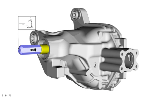
-
Using the special tool and a soft hammer, remove the pinion gear.
Use Special Service Tool: 205-460 Protector, Drive Pinion Thread.
Use the General Equipment: Copper Hammer
 |
-
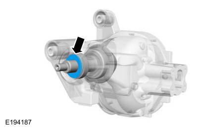
Remove the outer drive pinion bearing.
 |
-
Remove and discard the drive pinion collapsible spacer.
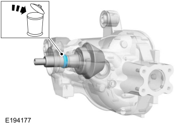 |
-
Remove the inner drive pinion bearing.
Use the General Equipment: Bearing Separator
 |
-
Remove the inner drive pinion bearing adjustment shim.
 |
-
Using the general equipment, remove and discard the drive pinion inner and outer bearing cups.
Use the General Equipment: Copper Hammer
Use the General Equipment: Punch
 |
-
If necessary.
Remove and discard the drive pinion oil baffle.
 |
-
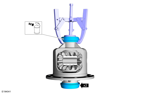
Using the general equipment and the special tool, remove and discard the differential bearings.
Use Special Service Tool: 205-D061 (D83T-4205-C2) Step Plate.
Use the General Equipment: Three Leg Puller
 |
Installation
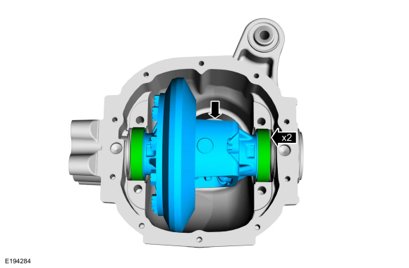
-
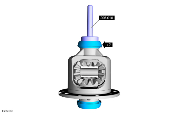
Using the special tools, install the new differential bearings.
Use Special Service Tool: 205-010 (T57L-4221-A2) Installer, Differential Side Bearing.
 |
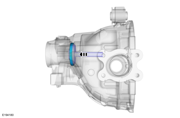
-
If removed.
Using the special tool, install the new drive pinion oil baffle.
Use Special Service Tool: 205-D044 (D81T-4221-A) Installer, Differential Carrier Bearing.
 |
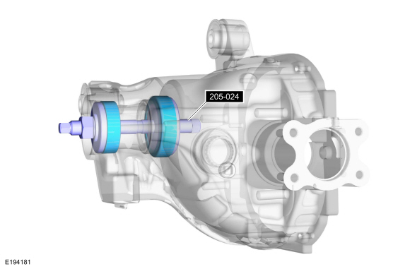
-
Using the special tools, install the new drive pinion inner and outer bearing cups.
Use Special Service Tool: 205-024 (T67P-4616-A) Installer, Drive Pinion Bearing Cup.
 |
-
NOTICE: Use the same drive pinion bearings and the drive pinion bearing adjustment shim from the drive pinion bearing adjustment shim selection procedure for final assembly or damage to the component may occur.
NOTE: Install new drive pinion bearings without any additional lubricant since the anti-rust oil provides adequate lubricant without upsetting the drive pinion bearing preload settings.
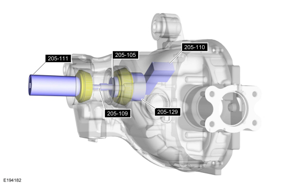
Assemble the special tools using the new inner and outer drive pinion bearings.
Use Special Service Tool: 205-105 (T76P-4020-A3) Adapter for 205-S127. , 205-109 (T76P-4020-A9) Adapter for 205-S127. , 205-110 (T76P-4020-A10) Gauge Block. , 205-111 (T76P-4020-A11) Handle. , 205-129 (T79P-4020-A18) Disc, Guage.
Torque: 19 lb.in (2.2 Nm)
 |
-
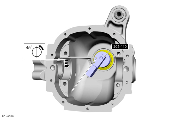
Rotate the special tools several half turns to ensure correct seating of the drive pinion bearings.
Use Special Service Tool: 205-110 (T76P-4020-A10) Gauge Block.
 |
-
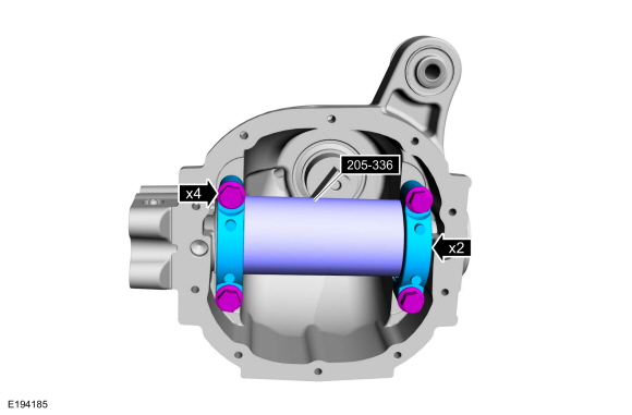
Install the special tool, the differential bearing caps and the differential bearing cap bolts.
Use Special Service Tool: 205-336 (T93P-4020-A) Gauge Tube, Drive Pinion.
Torque: 77 lb.ft (105 Nm)
 |
-
NOTE: Drive pinion bearing adjustment shims must be flat and clean.
NOTE: A slight drag should be felt for correct drive pinion bearing adjustment shim selection. Do not attempt to force the drive pinion bearing adjustment shim between the gauge block and the gauge tube. This will minimize selection of a drive pinion bearing adjustment shim thicker than required, which results in a deep tooth contact in final assembly of integral axle assemblies.
Use a drive pinion bearing adjustment shim as a gauge for drive pinion bearing adjustment shim selection.
-
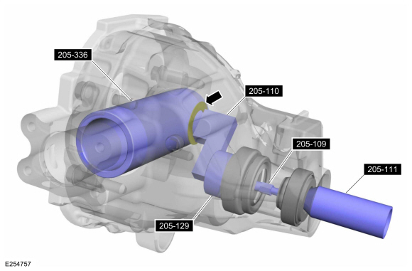
After the correct drive pinion bearing adjustment
shim thickness has been determined, remove all of the Adapters.
Use Special Service Tool: 205-109 (T76P-4020-A9) Adapter for 205-S127. , 205-110 (T76P-4020-A10) Gauge Block. , 205-111 (T76P-4020-A11) Handle. , 205-129 (T79P-4020-A18) Disc, Guage. , 205-336 (T93P-4020-A) Gauge Tube, Drive Pinion.
-
After the correct drive pinion bearing adjustment
shim thickness has been determined, remove all of the Adapters.
 |
-
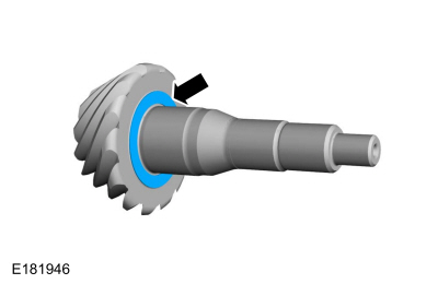
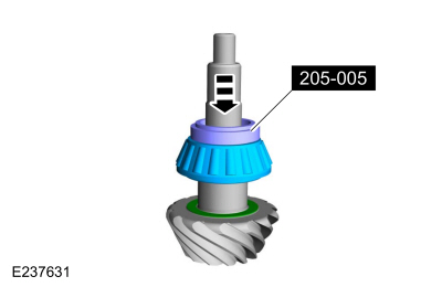
NOTE: The same drive pinion bearing from the previous steps must be used.
Install the drive pinion bearing and the selected drive pinion bearing adjustment shim until they are firmly seated on the drive pinion.
Use Special Service Tool: 205-005 (T53T-4621-C) Installer, Drive Pinion Bearing Cone.
Use the General Equipment: Hydraulic Press
 |
-
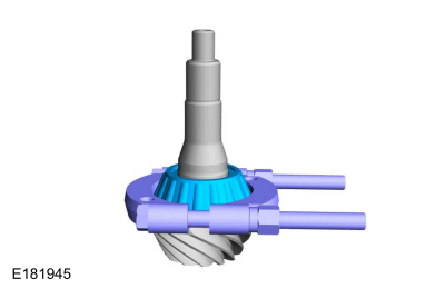
Install the pinion gear.
 |
-
Install the new drive pinion collapsible spacer.
 |
-
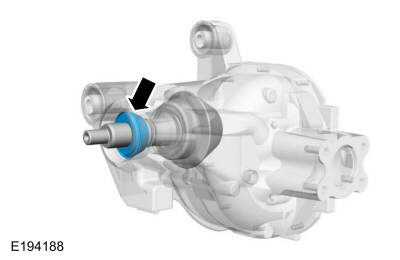
Install the outer drive pinion bearing.
|
-
Install the outer drive pinion oil slinger.
|
-
Install the drive pinion flange and seal.
Refer to: Drive Pinion Flange and Seal (205-03 Front Drive Axle/Differential, Removal and Installation).
-
NOTICE: It is necessary to loosely install the bearing caps and bolts to hold the differential in place.
Install the differential carrier and the differential carrier bearing cups as a assembly.
 |
-
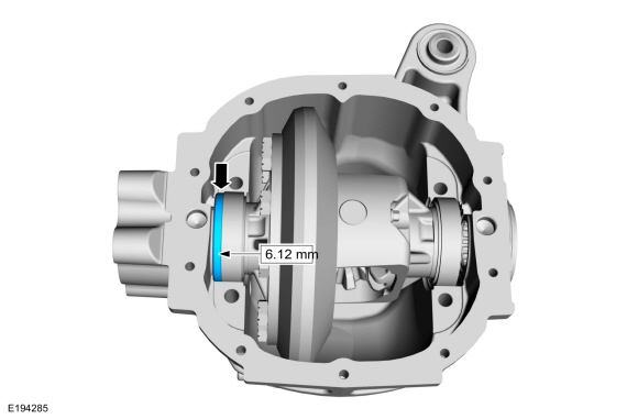
Install a 6.12 mm (0.241 in) differential bearing shim on the LH side of the differential bearing.
 |
-
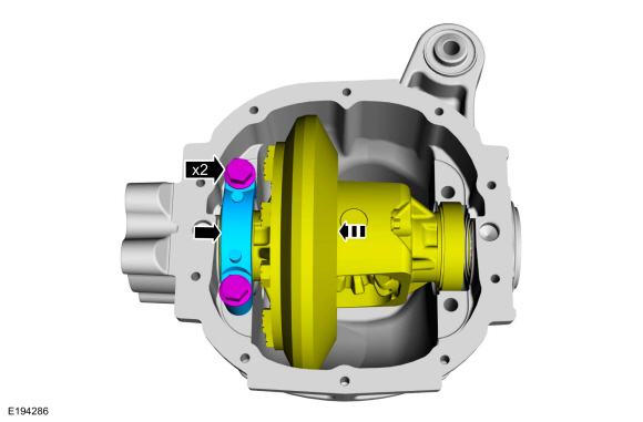
NOTE: Apply pressure toward the left side to make sure the left differential bearing cap is seated.
Install the LH differential bearing cap and loosely install the differential bearing cap bolts.
 |
-
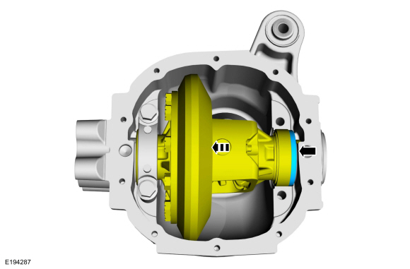
NOTE: Apply pressure toward the left side to make sure the left differential bearing cap is seated.
Install progressively thicker differential bearing shims on the right side until the thickest differential bearing shim can be inserted by hand.
 |
-
-
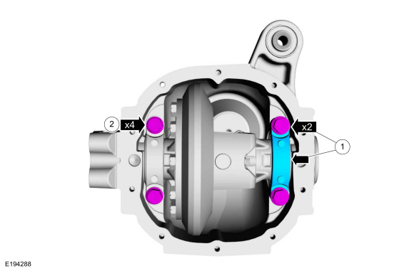
Install the RH differential bearing cap and bolts.
-
Tighten the differential bearing cap bolts.
Torque: 77 lb.ft (105 Nm)
-
Install the RH differential bearing cap and bolts.
 |
-
Rotate the differential carrier to make sure it turns freely.
 |
-
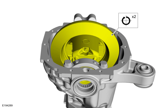
Using the dial indicator, measure the differential ring gear backlash at 4 equally spaced points.
-
To correct for high or low backlash, increase the
thickness of one differential bearing shim and decrease the thickness of
the other differential bearing shim by the same amount. Refer to the
following tables when adjusting the backlash.
Refer to: Specifications (205-03 Front Drive Axle/Differential, Specifications).
Use Special Service Tool: 100-002 (TOOL-4201-C) Holding Fixture with Dial Indicator Gauge.
-
To correct for high or low backlash, increase the
thickness of one differential bearing shim and decrease the thickness of
the other differential bearing shim by the same amount. Refer to the
following tables when adjusting the backlash.
 |
-
NOTE: Mark the differential bearing caps Top or Bottom and LH or RH appropriately before removing them. Always install the differential bearing caps in their original positions or damage to the component may occur.
Remove the differential cap bolts, differential caps and the carrier assembly.
 |
-
-
Measure the thickness of the selected right and left bearing shims.
Use the General Equipment: Caliper Gauge
-
To establish differential bearing preload, increase
both the left and right differential bearing shim thickness by 0.203 mm
(0.008 in).
-
Measure the thickness of the selected right and left bearing shims.
 |
-
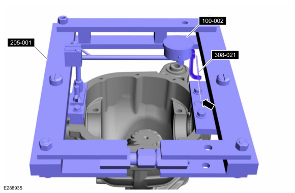
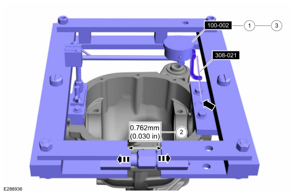
Install the Dial Indicator Gauge with Holding Fixture, Clutch Housing Gauge and Differential Carrier Spreader.
Use Special Service Tool: 205-001 (TOOL-4000-E) Spreader, Differential Carrier. , 100-002 (TOOL-4201-C) Holding Fixture with Dial Indicator Gauge. , 308-021 (T75L-4201-A) Gauge, Clutch Housing.
 |
-
NOTICE: Overspreading may damage the component. Do not spread the differential housing more then 0.762 mm (0.030 in).
NOTE: Tighten and loosen the differential carrier spreader screw to normalize the housing spreader adapters prior to taking the final Dial Indicator reading.
Spread the differential housing to the specification.
-
Adjust the Dial Indicator Gauge with Holding Fixture and Clutch Housing Gauge to zero.
Use Special Service Tool: 100-002 (TOOL-4201-C) Holding Fixture with Dial Indicator Gauge. , 308-021 (T75L-4201-A) Gauge, Clutch Housing.
-
Tighten the screw until spreading the differential housing to the specification.
-
Remove the Dial Indicator Gauge with Holding Fixture and Clutch Housing Gauge.
-
Adjust the Dial Indicator Gauge with Holding Fixture and Clutch Housing Gauge to zero.
 |
-
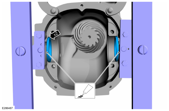
NOTICE: To avoid galling the case, insert shims with a light coating of grease before installing the differential assembly. If not carried out in this order, the aluminum housing may be damaged.
Place the differential bearing shims in the differential housing.
 |
-
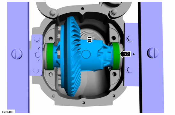
Install the differential carrier.
-
Position the differential bearing cups on the differential bearings.
-
Lower the differential carrier in place between the differential bearing shims.
-
Position the differential bearing cups on the differential bearings.
 |
-
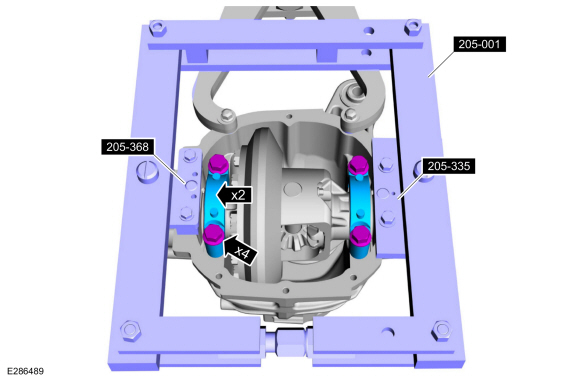
NOTICE: The fixture mounting bolts must have the minimum of 12.7 mm (0.500 In) of thread engagement in the carrier or damage to the component may occur.
NOTE: Always install the differential bearing caps in their original positions or damage to the component may occur.
NOTE: Hand-tighten the differential bearing cap bolts prior to releasing the carrier spreader.
-
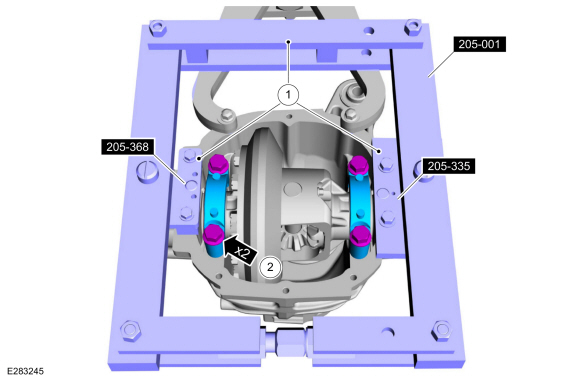
With the differential housing spread to 0.762 mm
(0.030 in) maximum. Install the differential caps and bolts in their
original locations and positions.
Use Special Service Tool: 205-001 (TOOL-4000-E) Spreader, Differential Carrier. , 205-368 (T96T-4000-A) Adapter for Differential Housing Spreader. , 205-335 (T93P-4000-A) Spreader, Differential Housing (Plate).
-
NOTE: Finger tighten the differential bearing cap bolts prior to releasing the carrier spreader.
Install the differential bearing caps and the differential bearing cap bolts in their original locations and positions.
-
With the differential housing spread to 0.762 mm
(0.030 in) maximum. Install the differential caps and bolts in their
original locations and positions.
 |
-
-
Loosen and Remove the special tools.
Use Special Service Tool: 205-001 (TOOL-4000-E) Spreader, Differential Carrier. , 205-368 (T96T-4000-A) Adapter for Differential Housing Spreader. , 205-335 (T93P-4000-A) Spreader, Differential Housing (Plate).
-
Tighten the differential bearing cap bolts.
Torque: 77 lb.ft (105 Nm)
-
Loosen and Remove the special tools.
 |
-
Rotate the differential carrier to make sure it turns freely.
|
-
Install the Dial Indicator Gauge with Holding Fixture and recheck the ring gear backlash.
Use Special Service Tool: 100-002 (TOOL-4201-C) Holding Fixture with Dial Indicator Gauge.
|
-
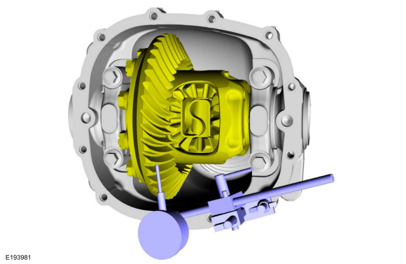
Apply marking compound and rotate the differential assembly 5 complete revolutions.
-
Verify an acceptable pattern check.
Refer to: Front Drive Axle (205-03 Front Drive Axle/Differential, Diagnosis and Testing).
-
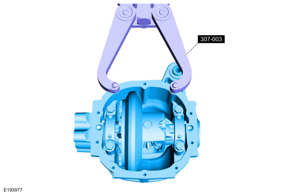
NOTICE: The fixture mounting bolts must have the minimum of 12.7 mm (0.500 In) of thread engagement in the carrier or damage to the component may occur.
Remove the axle assembly from the special tool.
Use Special Service Tool: 307-003 (T57L-500-B) Holding Fixture, Transmission.
 |
-
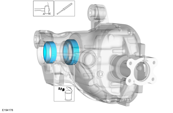
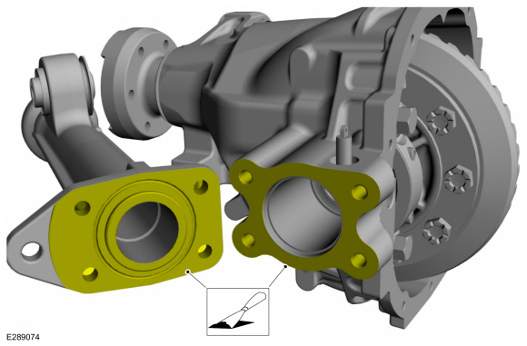
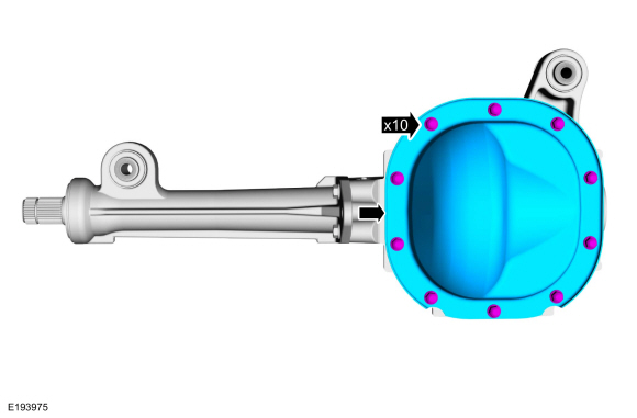
NOTE: Make sure that the mating surface and the bore is free of corrosion and foreign material, avoid particles getting into the bore. Particles might stick on the vent valve assembly and cause damage to vent valve.
Clean the mating surface of the axle and the axle tube.
 |
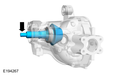
-
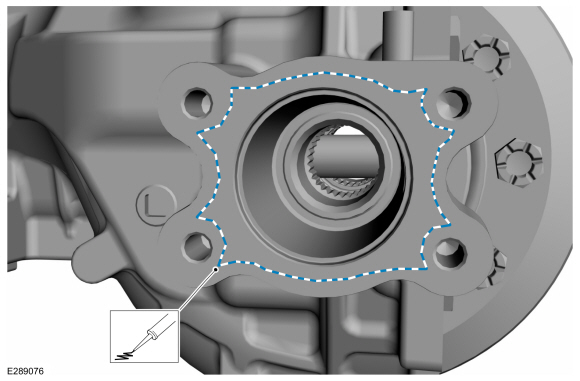
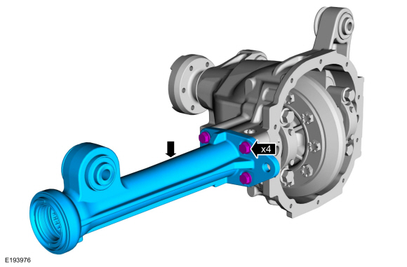
Apply a new continuous bead of sealant to the differential housing as shown.
Material: Motorcraft® Ultra Silicone Sealant / TA-29 (WSS-M4G323-A8)
 |
-
Install the axle tube and the axle tube bolts.
Torque: 54 lb.ft (73 Nm)
 |
-
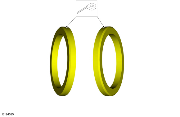
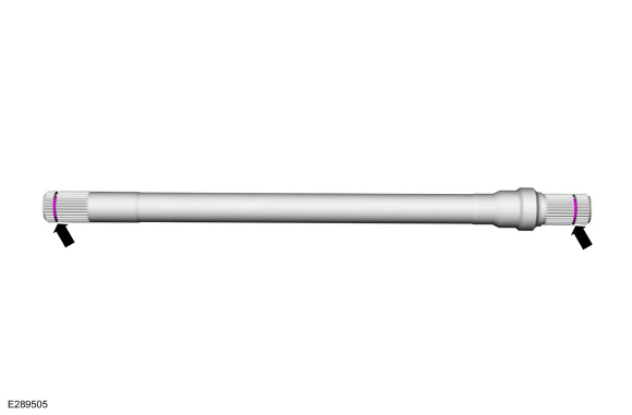
Install the new inner and outer circlips.
 |
-
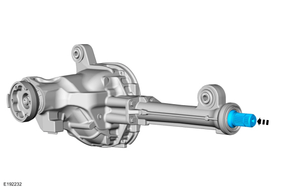
NOTE: The axle shaft is not fully seated until the circlip is engaged with the differential side gear.
Install the axle shaft.
 |
-
NOTE: Remove all of the silicone gasket and make sure the surfaces are free of oil before applying the new silicone gasket.
Clean the gasket mating surface of the axle and the differential housing cover.
 |
-
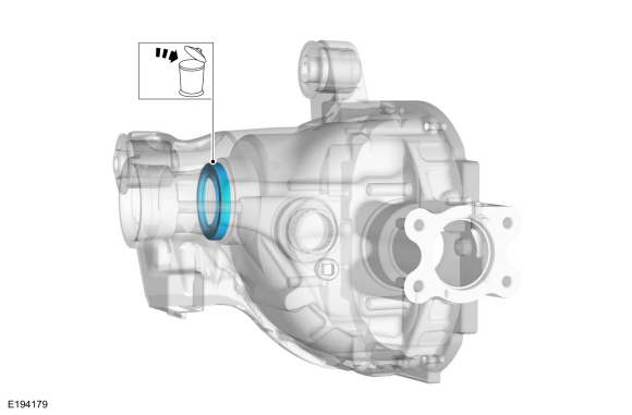
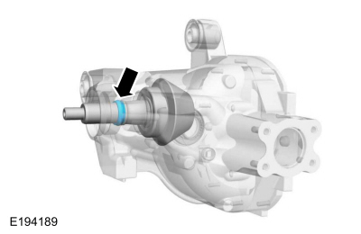
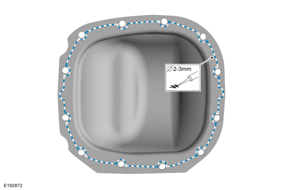
NOTE: The differential housing cover must be installed within 15 minutes of application of the silicone, or new sealant must be applied. If possible, allow one hour before filling with lubricant to make sure the silicone sealant has correctly cured.
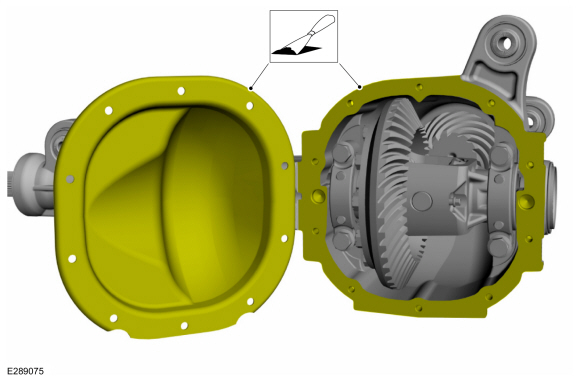
Apply a new continuous bead of sealant to the differential housing cover as shown.
Material: Motorcraft® Ultra Silicone Sealant / TA-29 (WSS-M4G323-A8)
 |
-
Install the differential cover and differential cover bolts.
Torque: 24 lb.ft (32 Nm)
 |
-
Install the axle assembly.
Refer to: Axle Assembly (205-03 Front Drive Axle/Differential, Removal and Installation).
 Axle Tube Bearing. Removal and Installation
Special Tool(s) /
General Equipment
205-123
(T78P-1177-A)
Installer, Axle Shaft Oil Seal
308-047
(T77F-1102-A)
Remover, Bearing Cup
Slide Hammer
Removal
Remove the axle shaft seal...
 Differential Carrier. Removal and Installation
Special Tool(s) /
General Equipment
100-002
(TOOL-4201-C)
Holding Fixture with Dial Indicator Gauge
205-001
(TOOL-4000-E)
Spreader, Differential Carrier
205-335
(T93P-4000-A)
Spreader, Differential Housing (Plate)TKIT-1993-FLMTKIT-1993-LMTKIT-1996-F/FM
205-368
(T96T-4000-A)
Adapter for Differential Housing SpreaderTKIT-1998-LM (NavigatoR..
Other information:
Lincoln Navigator 2018-2026 Workshop Manual: Ride Height Measurement. General Procedures
Special Tool(s) / General Equipment Surface Gauge Check Ride Height Measurement — Front NOTE: Make sure that the vehicle is positioned on a flat, level surface and the tires are inflated to the correct pressure. Vehicle should have a full tank of fuel. Jounce front and rear suspension vigorously to allow the vehicle to settle. Be..
Lincoln Navigator 2018-2026 Workshop Manual: Drive Pinion. Removal and Installation
Special Tool(s) / General Equipment 205-024 (T67P-4616-A) Installer, Drive Pinion Bearing Cup 205-090 (T75L-1165-B) Plate, Bearing/Oil Seal 205-111 (T76P-4020-A11) Handle 205-159 (T80T-4020-F42) Adapter for 205-S156 Pinion Depth GaugeT98T-1000-LM-1TKIT-1998-LM (NavigatoR) 205-160 (T80T-4020-F43) Adapter for 205-S156 ..
Categories
- Manuals Home
- 4th Gen Lincoln Navigator Service Manual (2018 - 2026)
- Neutral Flat Tow Activation and Deactivation. General Procedures
- Body and Paint
- Rear View Mirrors - System Operation and Component Description. Description and Operation
- Transmission Fluid Drain and Refill. General Procedures
- Power Running Board (PRB). Diagnosis and Testing
Front Driveshaft. Removal and Installation
Special Tool(s) / General Equipment
Crimping ToolMaterials
Name Specification Motorcraft® Premium Long-Life GreaseXG-1-E1 ESA-M1C75-B
Removal
With the vehicle in NEUTRAL, position the vehicle on a hoist.Refer to: Jacking and Lifting (100-02 Jacking and Lifting, Description and Operation).
Remove the bolts and the transmission shield.