Lincoln Navigator: Exterior Lighting / Headlamp Adjustment. General Procedures
Adjustment
-
NOTE: If the flash video link does not load or is incompatible with your browser, a .wmv version of the video can be accessed at: http://www.fordservicecontent.com/Ford_Content/videos/FusionHeadlampAdj2.wmv
Click on the link above to view video.
Click here to view a video version of this procedure.

All headlamp types
NOTE: Refer to the Owner's Literature for the headlamp adjustment screw location.
NOTE: Consult your state vehicle inspection manual for recommended tolerance ranges for visual aiming.
NOTE: Horizontal aim is not adjustable.
-
Identify the headlamp type. Vehicles are equipped
with Visually Optically Aligned Left (VOL) or Visually Optically Aligned
Right (VOR) headlamps. Molded in small letters on the headlamp lens is
one of the following: VOL and SAE or VOR and SAE.
-
NOTE: Before starting headlamp adjustment, entry conditions must be met.
-
Vehicle must be on level ground.
-
Tires must be correctly inflated.
-
Vehicle must be normally loaded.
-
Headlamps must be clean.
-
Headlamps must operate correctly.
-
Air suspension switch must be on (if equipped).
-
Vehicle ignition is in Run or Accessory On.
-
Vehicle must be on level ground.
-
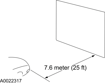
NOTE: The vertical wall or screen must be a minimum of 3 m (10 ft) wide.
Park the vehicle on a level surface approximately 7.6 m (25 ft) from the vertical wall or screen directly in front of it.
 |
-
NOTE: The bulb center of the low beam bulb is sometimes marked on the lens (circle, crosshair or other mark) or is the center of the low beam reflector, bulb shield or the low beam projector inner lens.
Measure the center of the headlamp height to ground and record the measurement.
 |
-
NOTE: Use a 3 m (10 ft) section of masking tape for the horizontal reference line.
-
For vehicles with headlamp bulb center heights
below 95 cm (37.5 inches), place the horizontal reference line equal to
the headlamp bulb center height.
-
For vehicles with headlamp bulb center heights
between 95 cm - 105 cm (37.5 - 41.5 inches), place the horizontal
reference line at the headlamp bulb center height minus 1.3 cm (0.5
inch).
-
For vehicles with headlamp bulb center heights
above 105 cm (41.5 inches), place the horizontal reference line at the
headlamp bulb center height minus 2.5 cm (1.0 inch).
-
For vehicles with headlamp bulb center heights
below 95 cm (37.5 inches), place the horizontal reference line equal to
the headlamp bulb center height.
-
NOTE: Carry out this procedure in a dark environment to effectively see the headlamp beam pattern.
Turn the low beam headlamps on to illuminate the wall or screen and open the hood.
-
NOTE: The cut off of the beam pattern is the horizontal line of the beam pattern where there is MAXIMUM change between light and dark.
On the wall or screen, locate the cut off of the beam pattern.
VOR-type headlamps
NOTE: Procedure applies to both left and right headlamps with VOR molded on lens.
-
NOTE: The appearance of the VOR beam pattern may vary between vehicles.
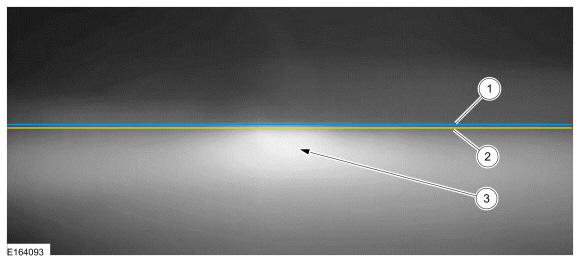
There is a distinct cutoff in the right portion of the beam pattern.
-
-
1 - Horizontal reference line
-
2 - Cut off
-
3 - High intensity zone
-
1 - Horizontal reference line
 |
-
NOTE: Align one headlamp while covering the other headlamp.
Align the headlamps to the horizontal reference line. Adjust the headlamp as necessary using the headlamp adjusting screw.
-
Repeat the previous step for the remaining headlamp.
VOL-type headlamps
NOTE: Procedure applies to both left and right headlamps with VOL molded on lens.
-
NOTE: The appearance of the VOL beam pattern may vary between vehicles.
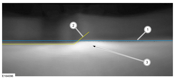
For VOL-type headlamps, there is a distinct cutoff in the left portion of the beam pattern. The edge of this cutoff should be positioned 5 CM (2 in) below the horizontal reference line.
-
-
1 - Horizontal reference line
-
2 - Cut off
-
3 - High intensity zone
-
1 - Horizontal reference line
 |
-
NOTE: Align one headlamp while covering the other headlamp.
Align the headlamps to the horizontal reference line. Adjust the headlamp as necessary using the headlamp adjusting screw.
-
Repeat the previous step for the remaining headlamp.
 Front Fog Lamp Adjustment. General Procedures
Adjustment
NOTE:
Horizontal aim is not adjustable. Consult your state
vehicle inspection center for recommended tolerance ranges for visual
aiming...
 Front Fog Lamp. Removal and Installation
Removal
NOTE:
Removal steps in this procedure may contain installation details.
NOTE:
LH (left-hand) front fog lamp shown, RH (right-hand) front fog lamp similar...
Other information:
Lincoln Navigator 2018-2026 Workshop Manual: Warning Chimes - System Operation and Component Description. Description and Operation
System Operation System Diagram *.sttxt { visibility: hidden; } *.stcallout { visibility: visible; } ..
Lincoln Navigator 2018-2026 Workshop Manual: Brake Disc Shield. Removal and Installation
Removal NOTE: Removal steps in this procedure may contain installation details. Remove the brake disc. Refer to: Brake Disc (206-03 Front Disc Brake, Removal and Installation). Remove the bolts and the brake disc shield. Torque: 133 lb.in (15 Nm) Installation To install, reverse the removal pro..
Categories
- Manuals Home
- 4th Gen Lincoln Navigator Service Manual (2018 - 2026)
- Transmission Fluid Drain and Refill. General Procedures
- Rear Bumper. Removal and Installation
- SYNC Module [APIM]. Removal and Installation
- Neutral Flat Tow Activation and Deactivation. General Procedures
- Body and Paint
Rear Stabilizer Bar Link. Removal and Installation
Removal
NOTE: Removal steps in this procedure may contain installation details.
With the vehicle in NEUTRAL, position it on a hoist.Refer to: Jacking and Lifting (100-02 Jacking and Lifting, Description and Operation).
NOTE: Use the hex-holding feature to prevent the stud from turning while removing the nut.
Remove and discard the 2 rear stabilizer bar link nuts and remove the rear stabilizer bar link.Torque: 46 lb.ft (63 Nm)
