Lincoln Navigator: Front Suspension - LHD 4WD / Wheel Knuckle. Removal and Installation
Special Tool(s) / General Equipment
 |
204-592 Separator, Lower Arm Ball Joint TKIT-2006C-FFMFLM TKIT-2006C-LM TKIT-2006C-ROW |
| Tie Rod End Remover | |
Removal
NOTICE: Suspension fasteners are critical parts that affect the performance of vital components and systems. Failure of these fasteners may result in major service expense. Use the same or equivalent parts if replacement is necessary. Do not use a replacement part of lesser quality or substitute design. Tighten fasteners as specified.
-
Remove the front wheel bearing and wheel hub.
Refer to: Front Wheel Bearing and Wheel Hub (204-01B Front Suspension - LHD 4WD, Removal and Installation).
-
NOTICE: Do not use power tools to remove or install the stabilizer bar link nuts. Damage to the stabilizer bar link ball joints and boots may occur.
NOTE: The stabilizer bar links are designed with low friction ball joints that have a low breakaway torque.
Use the hex-holding feature to prevent the ball stud from turning while removing or installing the stabilizer bar link nut. Remove and discard the front stabilizer bar link upper nut.
 |
-
Disconnect the battery ground cable.
Refer to: Battery Disconnect and Connect (414-01 Battery, Mounting and Cables, General Procedures).
-
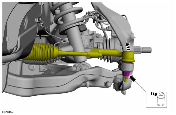
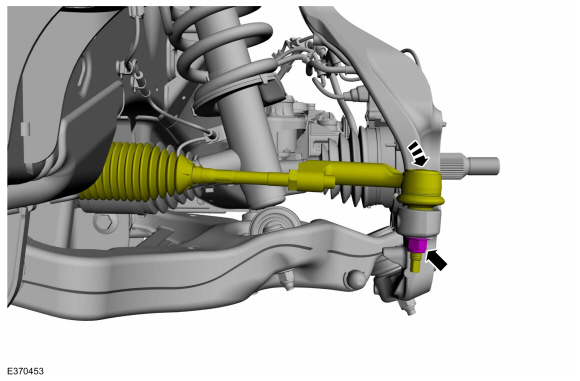
NOTICE: Do not use a hammer to separate the outer tie-rod end from the wheel knuckle or damage to the wheel knuckle may result.
NOTICE: Use care when installing the tie rod separator or damage to the outer tie-rod end boot may occur.
NOTE: Use the hex-holding feature to prevent the stud from turning while removing the nut.
Remove and discard the tie rod end nut and separate the tie rod end from the wheel knuckle.
Use the General Equipment: Tie Rod End Remover
 |
-
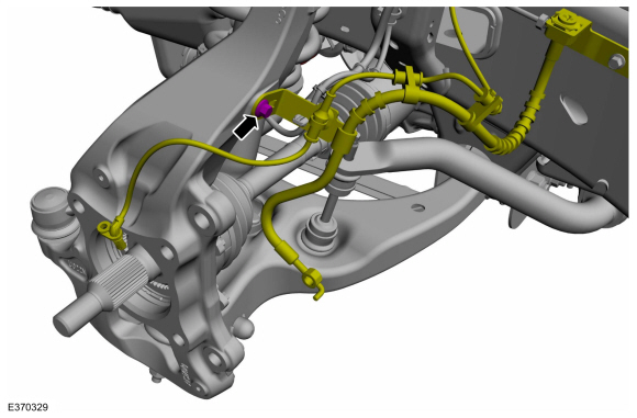
Remove the wheel speed sensor wire bracket bolt on the
wheel knuckle and position aside the wheel speed sensor wire.
 |
-
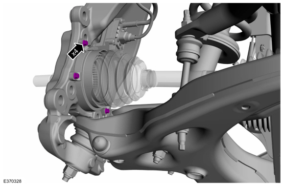
Remove the IWE bolts.
 |
-
Position the IWE and halfshaft.
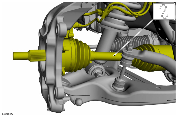 |
-
NOTICE: The suspension height sensors must be disconnected prior to servicing suspension components. Damage to the suspension height sensors and/or the vehicle dynamic suspension system may occur. The sensors will need to be recalibrated after reassembly.
NOTE: If equipped with dynamic suspension.
Remove the height sensor arm bracket screw and position aside the bracket.
 |
-
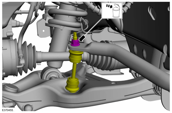
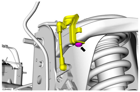
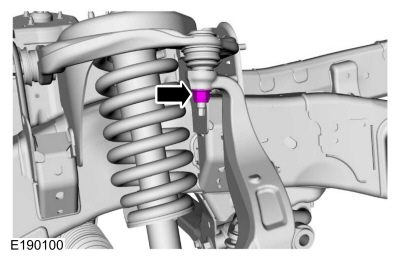
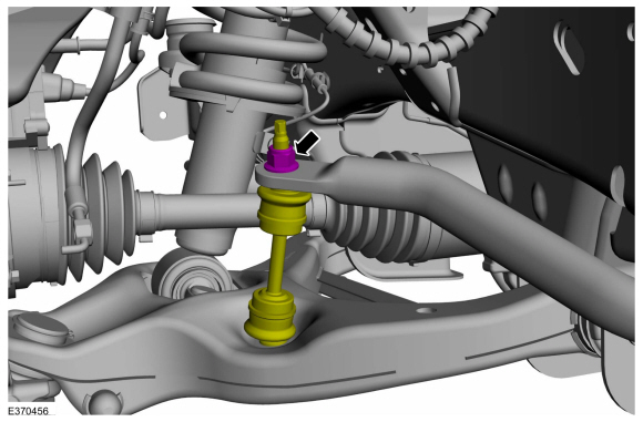
Remove and discard the upper ball joint nut.
 |
-
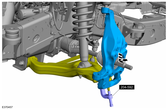
NOTE: Be sure not to damage the ball joint boot when installing the Ball Joint Separator.
Separate the upper ball joint from the wheel knuckle.
Use Special Service Tool: 204-592 Separator, Lower Arm Ball Joint.
 |
-
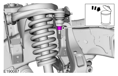
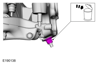
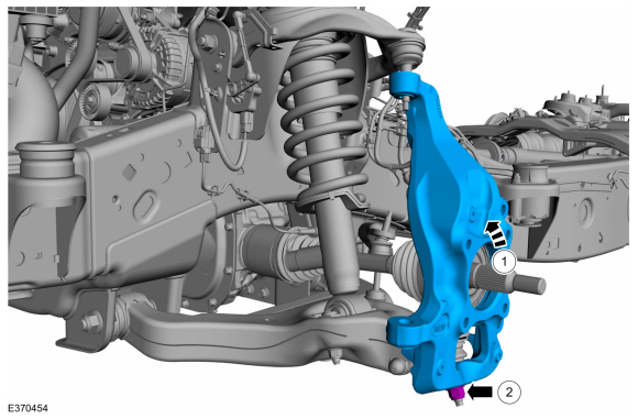
Remove and discard the lower ball joint nut.
 |
-
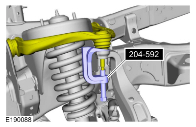
NOTICE: Do not use a prying device or separator fork between the ball joint and the wheel knuckle. Damage to the ball joint or ball joint seal may result.
NOTICE: Use care when releasing the lower arm and wheel knuckle into the resting position or damage to the ball joint seal may occur.
Separate the wheel knuckle from the lower ball joint and remove the wheel knuckle.
Use Special Service Tool: 204-592 Separator, Lower Arm Ball Joint.
 |
Installation
-
-
Install the wheel knuckle.
-
Install the new lower ball joint nut.
Torque: 76 lb.ft (103 Nm)
-
Install the wheel knuckle.
 |
-
Install the new upper ball joint nut.
Torque: 46 lb.ft (63 Nm)
 |
-
NOTICE: The suspension height sensors must be disconnected prior to servicing suspension components. Damage to the suspension height sensors and/or the vehicle dynamic suspension system may occur. The sensors will need to be recalibrated after reassembly.
NOTE: If equipped with dynamic suspension.
Position the height sensor arm bracket and install the height sensor arm bracket screw.
Torque: 177 lb.in (20 Nm)
|
-
Install the IWE bolts.
Torque: 106 lb.in (12 Nm)
|
-
Position the wheel speed sensor wire and install the wheel speed sensor wire bracket bolt on the wheel knuckle.
Torque: 18 lb.ft (25 Nm)
|
-
NOTICE: Do not use a hammer to separate the outer tie-rod end from the wheel knuckle or damage to the wheel knuckle may result.
NOTICE: Use care when installing the tie rod separator or damage to the outer tie-rod end boot may occur.
NOTE: Use the hex-holding feature to prevent the stud from turning while installing the nut.
Position the tie rod end and install the new tie rod end nut.
Torque: 76 lb.ft (103 Nm)
 |
-
Connect the battery ground cable.
Refer to: Battery Disconnect and Connect (414-01 Battery, Mounting and Cables, General Procedures).
-
NOTICE: Do not use power tools to remove the stabilizer bar link nut. Damage to the stabilizer bar link ball joint or boot may occur.
NOTE: The stabilizer bar links are designed with low friction ball joints that have a low breakaway torque.
Use the hex-holding feature to prevent the ball stud from turning while removing or installing the stabilizer bar link nut. Position the front stabilizer bar link and install the new front stabilizer bar link upper nut.
Torque: 59 lb.ft (80 Nm)
 |
-
Install the front wheel bearing and wheel hub.
Refer to: Front Wheel Bearing and Wheel Hub (204-01B Front Suspension - LHD 4WD, Removal and Installation).
- If equipped with dynamic suspension, calibrate the suspension height sensor. Connect the scan tool and carry out the Ride Height Calibration routine. Follow the scan tool directions.
 Upper Arm. Removal and Installation
Removal
NOTICE:
Suspension fasteners are critical parts that affect the
performance of vital components and systems. Failure of these fasteners
may result in major service expense...
 Wheel Studs. Removal and Installation
Special Tool(s) /
General Equipment
211-023
(T74P-3044-A1)
C-Frame and Screw
Removal
NOTICE:
Suspension fasteners are critical parts that affect the
performance of vital components and systems...
Other information:
Lincoln Navigator 2018-2026 Workshop Manual: Second Row Center Seat Backrest Cover. Removal and Installation
Removal NOTE: Removal steps in this procedure may contain installation details. Remove the second row center seat. Refer to: Second Row Center Seat (501-10B Second Row Seats, Removal and Installation). Remove the second row center seat head restraint guide sleeves...
Lincoln Navigator 2018-2026 Workshop Manual: Battery and Cables - System Operation and Component Description. Description and Operation
System Operation Battery and Cables The battery and cable system consists of the following components: Battery Battery tray Battery monitoring sensor Negative battery cable Positive battery cable High current BJB Vehicles are equipped with a 12-volt, maintenance-free battery...
Categories
- Manuals Home
- 4th Gen Lincoln Navigator Service Manual (2018 - 2026)
- Rear Bumper. Removal and Installation
- Liftgate Trim Panel. Removal and Installation
- SYNC Module [APIM]. Removal and Installation
- Front Seat. Removal and Installation
- Brake Service Mode Activation and Deactivation. General Procedures
Front Driveshaft. Removal and Installation
Special Tool(s) / General Equipment
Crimping ToolMaterials
Name Specification Motorcraft® Premium Long-Life GreaseXG-1-E1 ESA-M1C75-B
Removal
With the vehicle in NEUTRAL, position the vehicle on a hoist.Refer to: Jacking and Lifting (100-02 Jacking and Lifting, Description and Operation).
Remove the bolts and the transmission shield.