Lincoln Navigator: Climate Control System - General Information / Climate Control System - Component Location. Description and Operation
| Item | Description |
|---|---|
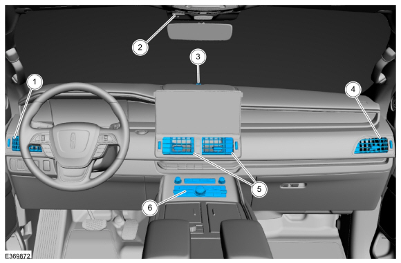
| 1 | Driver Side Register |
| 2 | In-Vehicle Temperature & Humidity Sensor |
| 3 | Auto Lamp & Sunload Sensor |
| 4 | Passenger Side Register |
| 5 | Center Registers |
| 6 | FCIM & HVAC Module |
| Item | Description |
|---|---|
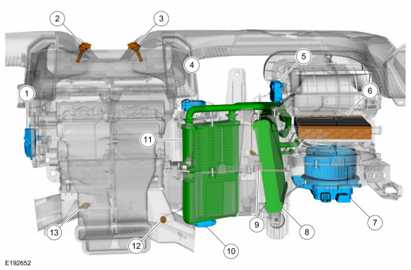
| 1 | Air Distribution Door Actuator |
| 2 | Driver Side Register Air Discharge Temperature Sensor |
| 3 | Passenger Side Register Air Discharge Temperature Sensor |
| 4 | Passenger Side Temperature Door Actuator |
| 5 | Air Inlet Door Actuator |
| 6 | Cabin Air Filter |
| 7 | Blower Motor Control Module |
| 8 | Evaporator |
| 9 | Evaporator Temperature Sensor |
| 10 | Temperature Door Actuator |
| 11 | Heater Core |
| 12 | Passenger Side Footwell Air Discharge Temperature Sensor |
| 13 | Driver Side Footwell Air Discharge Temperature Sensor |
| Item | Description |
|---|---|
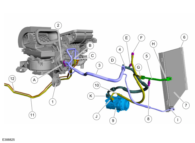
| 1 | Condensation drain |
| 2 | Thermostatic expansion valve |
| 3 | Thermostatic expansion valve manifold and tube assembly |
| 4 | A/C compressor inlet line |
| 5 | A/C condenser to A/C compressor outlet line |
| 6 | Desiccant bag |
| 7 | Condenser |
| 8 | A/C pressure transducer |
| 9 | A/C compressor |
| 10 | A/C condenser outlet line |
| 11 | Rear evaporator outlet line |
| 12 | Rear evaporator inlet line |
| A | Thermostatic expansion valve fitting |
| B | Rear evaporator outlet line fitting |
| C | Rear evaporator inlet line fitting |
| D | A/C compressor inlet line to A/C thermostatic expansion valve manifold and tube assembly fitting |
| E | Low side service port |
| F | High side service port |
| G | Condenser to A/C compressor outlet line fitting |
| H | Condenser inlet fitting |
| I | Condenser outlet fitting |
| J | Compressor outlet fitting |
| K | Compressor inlet fitting |
| Item | Description |
|---|---|
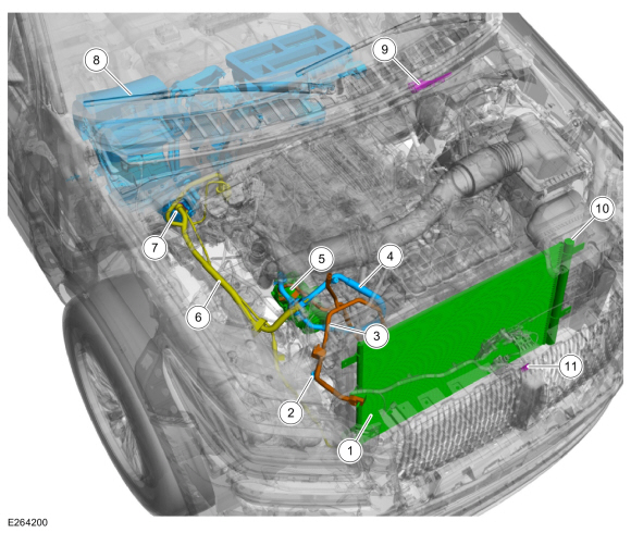
| 1 | Condenser |
| 2 | A/C Pressure Transducer |
| 3 | A/C Compressor Outlet Line |
| 4 | A/C Compressor Inlet Line |
| 5 | A/C Compressor |
| 6 | Thermostatic Expansion Valve Manifold and Tube Assembly |
| 7 | Thermostatic Expansion Valve |
| 8 | Climate Control Housing |
| 9 | If equipped, Ambient Air Quality Sensor |
| 10 | Desiccant Bag |
| 11 | Ambient Air Temperature Sensor |

 Climate Control System - System Operation and Component Description. Description and Operation
System Operation
System Diagram
E371291
*.sttxt {
visibility: hidden;
}
*.stcallout {
visibility: visible;
}
1
GWM
2
Cabin heater
coolant pump
3
Externally Controlled
Variable Dsiplacement
Compressor (EVDC)
..
Other information:
Lincoln Navigator 2018-2026 Workshop Manual: Engine Rear Undershield. Removal and Installation
NOTICE: Support the engine rear undershield while the fasteners are being removed and installed. Do not support the engine rear undershield by any less than the total number of fasteners at any time. Holding the shield in its correct position, remove the fasteners and the engine rear undershield. Torque: 71 lb.in (8 Nm) ..
Lincoln Navigator 2018-2026 Workshop Manual: Exhaust Gas Recirculation (EGR) System. Diagnosis and Testing
Diagnostic Trouble Code (DTC) Chart Diagnostics in this manual assume a certain skill level and knowledge of Ford-specific diagnostic practices. REFER to: Diagnostic Methods (100-00 General Information, Description and Operation). Module DTC Description Action PCM P0401:00 EGR 'A' Flow Insufficient Detected: No Sub Type Information GO to Pinpoint Test HE PC..
Categories
- Manuals Home
- 4th Gen Lincoln Navigator Service Manual (2018 - 2026)
- Liftgate Trim Panel. Removal and Installation
- Windshield Washer Pump. Removal and Installation
- Vehicle Dynamics Control Module (VDM). Removal and Installation
- SYNC Module [APIM]. Removal and Installation
- Transmission Fluid Level Check. General Procedures
Differential Case Runout Check. General Procedures
Special Tool(s) / General Equipment
 205-1016
Installer, Differential Bearing
TKIT-2014D-ROW2
TKIT-2014D-FL_ROW
 205-153
(T80T-4000-W)
205-153
(T80T-4000-W)
Handle
 205-D061
(D83T-4205-C2)
205-D061
(D83T-4205-C2)
Step Plate Dial Indicator Three Leg Puller Punch