Lincoln Navigator: General Information / Wire Terminal Inspection and Removal. General Procedures
Disconnect
-
Refer to: Health and Safety Precautions (100-00 General Information, Description and Operation). WARNING:
Before beginning any service procedure in this
section, refer to Health and Safety Precautions in section 100-00
General Information. Failure to follow this instruction may result in
serious personal injury.
WARNING:
Before beginning any service procedure in this
section, refer to Health and Safety Precautions in section 100-00
General Information. Failure to follow this instruction may result in
serious personal injury.
NOTE: To avoid wiring pin (terminal) damage, Rotunda Flex Probes NUD105-R025D or Terminal Probe Kit 29-011A must be used to connect test equipment or jumper wires to pins (terminals).
- Male to female pin (terminal) fit is critical for correct connection and durability.
- Pin (terminal) fit may be checked by using the mating pin (terminal) to test for normal separation force (a damaged pin or terminal will have very low separation force from the mating pin or terminal).
- Correctly checking the separation force of small pins (terminals) may require removal of the connector terminal guide/retainer if it adds drag to the pin (terminal) insertion or removal.
- For more detail on the replacement of damaged connectors or pins (terminals) refer to the video below.
Click here to view a video version of this procedure.

-
NOTE: The connector hard-shell information, which is measured in millimeters is the distance from the front face of the connector to the engagement point on the terminal release tang. Mark the listed distance on the terminal removal tool prior to removing the terminal.
NOTE: The dimensions of the connector hard-shell and the connector terminals release tang are listed above the corresponding graphics.
-
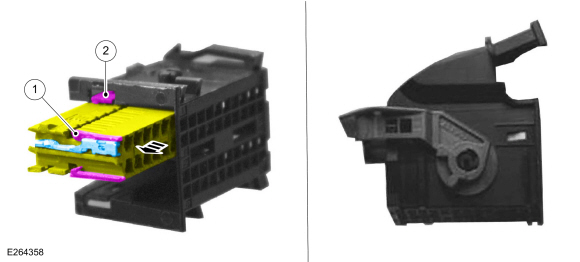
Audio Front Control Module (ACM), Body Control Module (BCM) and Instrument Panel Cluster (IPC) Electrical Connector
Callout Connector 1 External terminal release tang 2 Electrical connector locking tab
 |
-
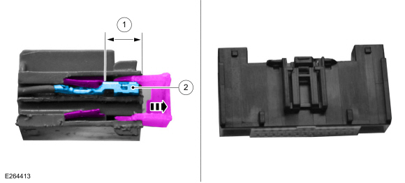
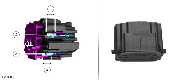
Audio Front Control Module (ACM), Front Controls Interface Module (FCIM), Gateway Module A (GWM), and Heating, Ventilation and Air Conditioning (HVAC) Control Module Electrical Connector
Callout Connector 1 Distance to release tang - 0.2953 in ( 7.5 mm) (inner terminal) - 0.4646 in ( 11.8 mm) (outer terminal) 2 Terminal width size - 0.0244 in ( .62 mm) (inner terminal) - 0.1102 in ( 2.8 mm) (outer terminal)
 |
-
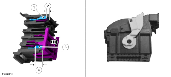
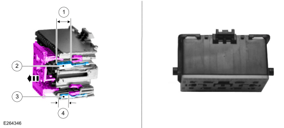
Body Control Module (BCM) Electrical Connector
Callout Connector 1 Terminal width size - 0.1102 in ( 2.8 mm) (inner terminal) - 0.2480 in ( 6.3 mm) (outer terminal) 2 Distance to release tang - 0.1260 in ( 3.2 mm) (inner terminal) - 0.1575 in ( 4 mm) (outer terminal) 3 Terminal width size - 0.0591 in ( 1.5 mm) 4 Distance to release tang - 0.3780 in ( 9.6 mm) (lower terminal)
 |
-
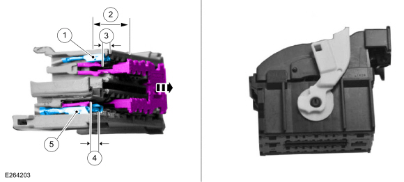
Body Control Module (BCM) Electrical Connector
Callout Connector 1 Terminal width size - 0.0591 in ( 1.5 mm) (inner terminal) - 0.1102 in ( 2.8 mm) (outer terminal) 2 Distance to release tang - 0.3780 in ( 9.6 mm) (inner terminal) 3 Distance to release tang - 0.1575 in ( 4 mm) 4 Distance to release tang - 0.1575 in ( 4 mm) 5 Terminal width size - 0.2480 in ( 6.3 mm)
 |
-
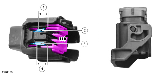
Body Harness In-line Electrical Connector
Callout Connector 1 Distance to release tang - 0.3346 in ( 8.5 mm) 2 Terminal width size - 0.1102 in ( 2.8 mm) 3 Terminal width size - 0.0591 in ( 1.5 mm) 4 Distance to release tang - 0.3858 in ( 9.8 mm) (inner)
 |
-
Body Harness In-line Electrical Connector
Callout Connector 1 Distance to release tang - 0.3543 in ( 9 mm) 2 Terminal width size - 0.0591 in ( 1.5 mm) (inner terminal) - 0.1102 in ( 2.8 mm) (outer terminal) 3 Terminal width size - 0.2480 in ( 6.3 mm) 4 Distance to release tang - 0.3543 in ( 9 mm)
 |
-
Body Harness In-line and Seat Harness Electrical Connector
Callout Connector 1 Distance to release tang - 0.4331 in ( 11 mm) 2 Terminal width size - 0.0591 in ( 1.5 mm) 3 Terminal width size - 0.0591 in ( 1.5 mm) 4 Distance to release tang - 0.4331 in ( 11 mm)
 |
-
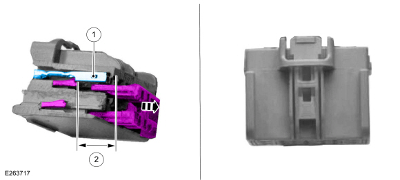
Body Harness In-line and Seat Module Electrical Connector
Callout Connector 1 Terminal width size - 0.0591 in ( 1.5 mm) 2 Distance to release tang - 0.3937 in ( 10 mm)
 |
 Wheel and Tire Health and Safety Precautions. Description and Operation
WARNING:
Never inflate a tire that has been run flat without first
removing the tire from the wheel to inspect for damage. A damaged tire
can fail during inflation...

Other information:
Lincoln Navigator 2018-2026 Workshop Manual: Roof Opening Panel - System Operation and Component Description. Description and Operation
System Operation Item Description 1 BCM 2 Sliding Glass Motor 3 Roof Opening Panel Control Switch 4 Shield Motor 5 K Bus (not used for external communication) Switch Operation There are three switches located in the overhead console. The RH switch is for the front sliding glass panel an..
Lincoln Navigator 2018-2026 Workshop Manual: Tire Pressure Monitoring System (TPMS) Sensor Location Calibration. General Procedures
Special Tool(s) / General Equipment 204-D081A (204-D081) Tire Pressure Monitor (TPMS) Ford Diagnostic Equipment Programming NOTE: The TPMS can be placed into learn mode using a diagnostic scan tool or manually where a diagnostic scan tool is not available. NOTE: The horn will sound once and the TPMS indicator will flash if the training mode has been..
Categories
- Manuals Home
- 4th Gen Lincoln Navigator Service Manual (2018 - 2026)
- Rear Bumper. Removal and Installation
- Neutral Flat Tow Activation and Deactivation. General Procedures
- Rear View Mirrors - System Operation and Component Description. Description and Operation
- All Terrain Control Module (ATCM). Removal and Installation
- Telematics Control Unit (TCU) Module. Removal and Installation
Rear Drive Axle and Differential. Diagnosis and Testing
Symptom Chart(s)
Diagnostics in this manual assume a certain skill level and knowledge of Ford-specific diagnostic practices.
REFER to: Diagnostic Methods (100-00 General Information, Description and Operation).
Symptom Chart - Differential
Symptom Chart - Differential
Condition Actions Axle overheating GO to Pinpoint Test A Broken gear teeth on the ring gear or pinion GO to Pi