Lincoln Navigator: Rear Suspension / Wheel Knuckle. Removal and Installation
Special Tool(s) /
General Equipment
 |
204-592/1
Adapter for 204-592 |
Removal
NOTICE:
Suspension fasteners are critical parts that affect the
performance of vital components and systems. Failure of these fasteners
may result in major service expense. Use the same or equivalent parts if
replacement is necessary. Do not use a replacement part of lesser
quality or substitute design. Tighten fasteners as specified.
-
Remove the rear wheel bearing and wheel hub.
Refer to: Wheel Bearing and Wheel Hub (204-02 Rear Suspension, Removal and Installation).
-
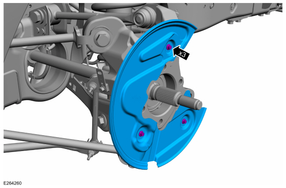
Remove the 3 bolts and the brake disc shield.
-
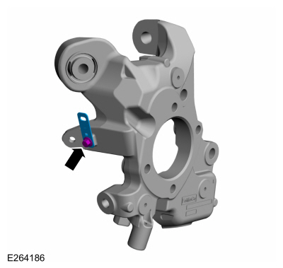
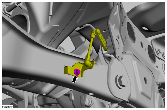
NOTE:
If equipped with dynamic suspension.
Remove the ride height sensor arm bracket bolt and position the bracket aside.
-
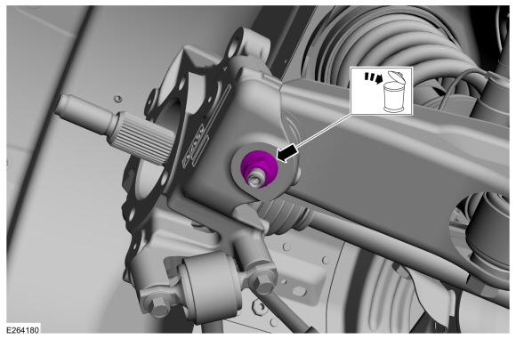
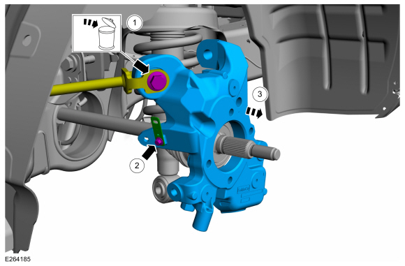
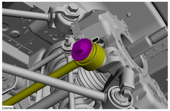
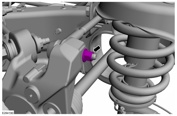
Remove and discard the upper arm-to-wheel knuckle nut.
-
Separate the upper ball joint from the wheel knuckle.
Use Special Service Tool: 204-592/1
Adapter for 204-592.
-
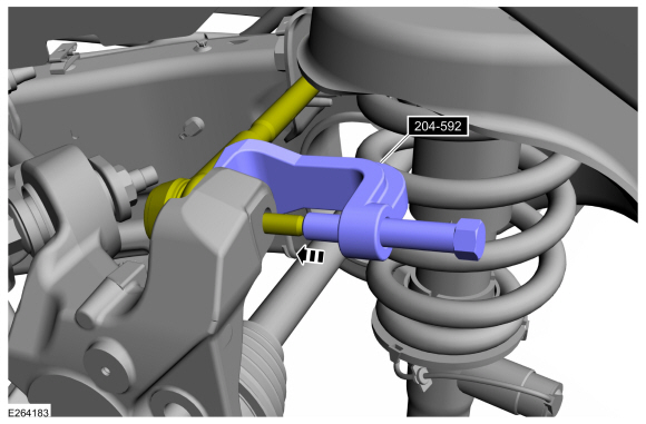
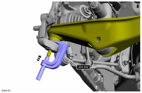
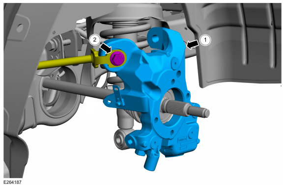
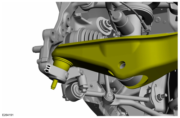
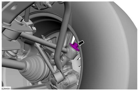
Remove and discard the lower ball joint nut.
-
Separate the lower ball joint from the wheel knuckle.
Use Special Service Tool: 204-592/1
Adapter for 204-592.
-
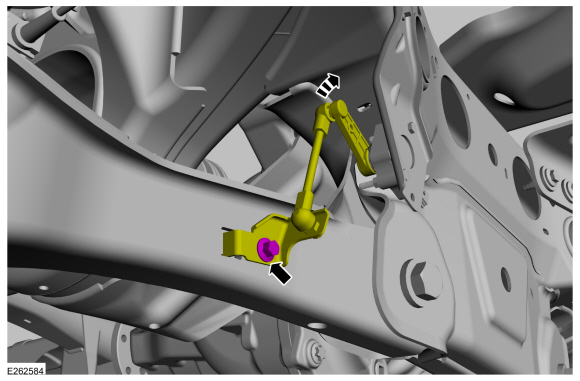
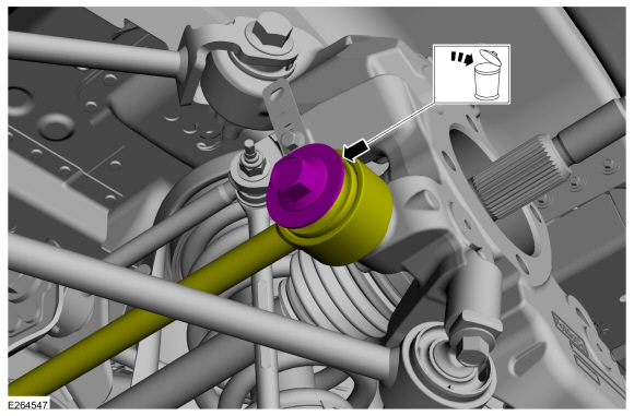
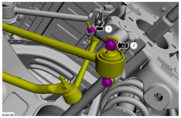
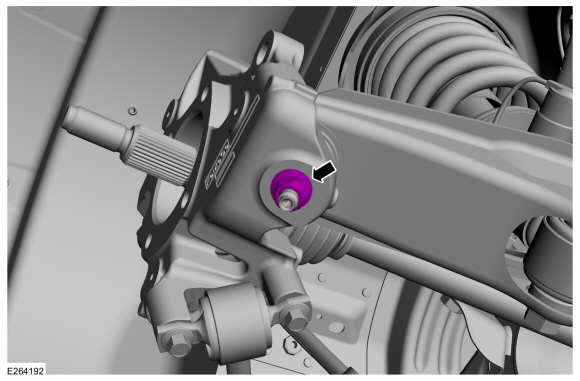
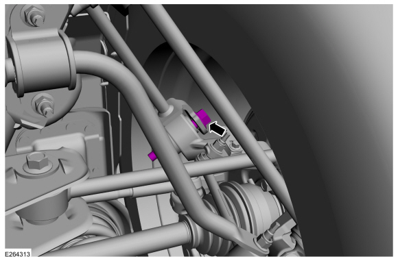
Remove and discard the bolt and disconnect the toe link from the wheel knuckle.
-
NOTE:
Use the hex-holding feature to prevent the stud from turning while removing the nut.
-
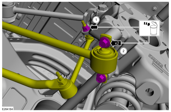
Remove and discard the 2 bolts and disconnect the lower trailing arm from the wheel knuckle.
-
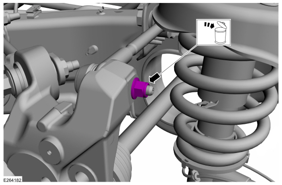
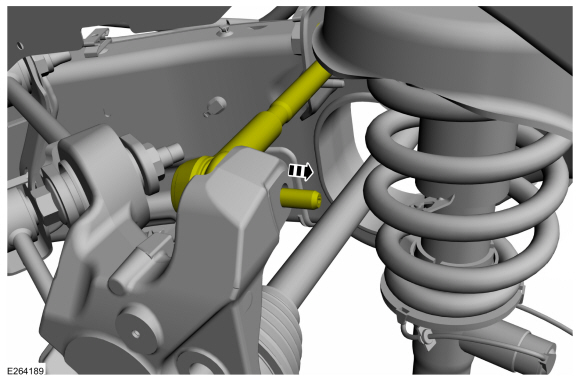
Using the hex-holding feature, remove and discard
the stabilizer bar link nut and disconnect the link from the wheel
knuckle.
-
-
Remove and discard the upper trailing arm-to-wheel knuckle bolt and position the upper trailing arm.
-
Remove the bracket bolt and the bracket.
-
Remove the wheel knuckle.
Installation
-
Install the bracket onto the wheel knuckle.
Torque:
30 lb.ft (40 Nm)
-
NOTE:
Only tighten the bolt finger tight at this stage.
-
Install the wheel knuckle.
-
Position the upper trailing arm onto the wheel
knuckle and install the new upper trailing arm-to-wheel knuckle bolt.
-
-
Position the rear stabilizer bar link to the wheel knuckle and install the new rear stabilizer bar link nut.
Torque:
46 lb.ft (63 Nm)
-
Position the lower trailing arm to the wheel knuckle and Install the 2 new bolts.
Torque:
76 lb.ft (103 Nm)
-
NOTE:
Only tighten the bolt finger tight at this stage.
Position the toe link onto the wheel knuckle and install the new toe link-to-wheel knuckle bolt.
-
Position the lower ball joint into the wheel knuckle.
-
Install the new lower arm ball joint nut.
Torque:
76 lb.ft (103 Nm)
-
Position the upper arm into the wheel knuckle.
-
Install the new upper arm nut.
Torque:
46 lb.ft (63 Nm)
-
NOTE:
If equipped with dynamic suspension.
Position the ride height sensor arm bracket and install the bolt.
Torque:
177 lb.in (20 Nm)
-
Install the 3 bolts and the brake disc shield.
Torque:
159 lb.in (18 Nm)
-
Install the rear wheel bearing and wheel hub.
Refer to: Wheel Bearing and Wheel Hub (204-02 Rear Suspension, Removal and Installation).
-
Lower the vehicle so that the weight of the vehicle is on the wheel and tire assemblies.
-
Tighten the new toe link-to-wheel knuckle bolt.
Torque:
166 lb.ft (225 Nm)
-
Tighten the new upper trailing arm-to-wheel knuckle bolt.
Torque:
184 lb.ft (250 Nm)
-
NOTE:
If equipped with continuous controlled damping (CCD) suspension.
Calibrate the suspension height sensor. Connect the scan
tool and carry out the Ride Height Calibration routine. Follow the scan
tool directions.
Removal
NOTICE:
Suspension fasteners are critical parts that affect the
performance of vital components and systems. Failure of these fasteners
may result in major service expense...
Special Tool(s) /
General Equipment
211-023
(T74P-3044-A1)
C-Frame and Screw
Removal
NOTICE:
Suspension fasteners are critical parts that affect the
performance of vital components and systems...
Other information:
Special Tool(s) /
General Equipment
6.5 mm Drill Bit
Spherical Cutter
Self-Piercing Rivet (SPR) Remover/Installer
Belt Sander
Blind Rivet Gun
Air Body Saw
MIG/MAG Welding Equipment
Locking Pliers
Materials
Name
Specification
Metal Bonding AdhesiveTA-1, TA-1-B, 3M™ 08115, LORD Fusor® 108B, Henkel Teroson EP 5..
Removal
NOTE:
LH side shown, RH side similar.
NOTE:
Removal steps in this procedure may contain installation details.
Remove the rear door window glass.
Refer to: Rear Door Window Glass (501-11 Glass, Frames and Mechanisms, Removal and Installation).
Remove the adhesive tape cover.
Remove t..
 Wheel Bearing and Wheel Hub. Removal and Installation
 Wheel Studs. Removal and Installation