Lincoln Navigator: Fuel Charging and Controls - Turbocharger - 3.5L EcoBoost (272kW/370PS) / Wastegate Control Actuator RH. Removal and Installation
Removal
NOTICE: The turbocharger compressor vanes can be damaged by even the smallest particles. When removing any turbocharger or engine air intake system component, ensure that no debris enters the system. Failure to do so may result in damage to the turbocharger.
-
With the vehicle in NEUTRAL, position it on a hoist.
Refer to: Jacking and Lifting (100-02 Jacking and Lifting, Description and Operation).
-
Remove the right front fender splash shield.
Refer to: Fender Splash Shield (501-02 Front End Body Panels, Removal and Installation).
-
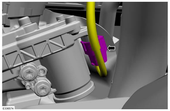
Disconnect the wastegate control actuator electrical connector.
 |
-
-
Note the correct orientation of the wastegate
control actuator linkage, the long section of the linkage goes towards
the actuator, and the curve to the outside away from the engine, to
insure the correct installation.
-
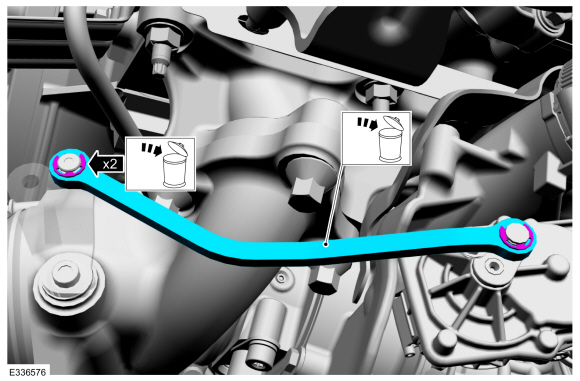
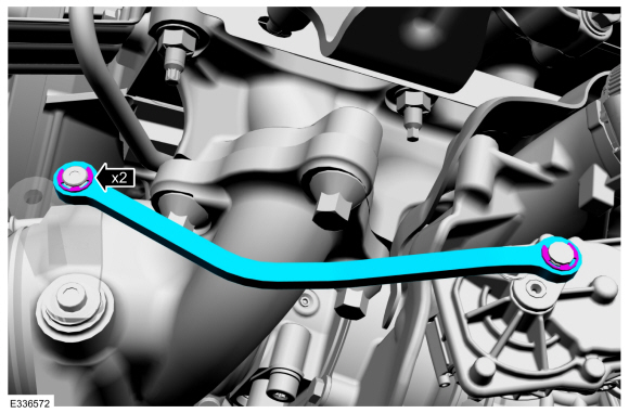
Remove and discard the wastegate control actuator linkage e-clips, then remove and discard the linkage.
-
Note the correct orientation of the wastegate
control actuator linkage, the long section of the linkage goes towards
the actuator, and the curve to the outside away from the engine, to
insure the correct installation.
 |
-
Remove and discard the wastegate control actuator linkage wave washers.
 |
-
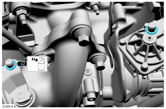
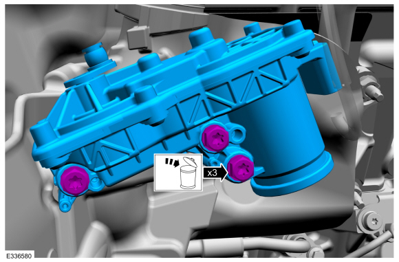
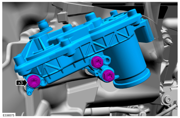
Remove and discard the wastegate control actuator bolts, then remove the wastegate control actuator.
 |
Installation
-
Install the wastegate control actuator, then install and tighten the new bolts.
Torque: 62 lb.in (7 Nm)
 |
-
Install the new wastegate control actuator linkage wave washers.
 |
-
-
The the wastegate control actuator linkage must be
installed in the correct orientation with the long section of the
linkage towards the actuator, and the curve to the outside away from the
engine, as noted in the removal, or the linkage will bind.
-
Install the new wastegate control actuator linkage, then install the new e-clips.
-
The the wastegate control actuator linkage must be
installed in the correct orientation with the long section of the
linkage towards the actuator, and the curve to the outside away from the
engine, as noted in the removal, or the linkage will bind.
 |
-
Connect the wastegate control actuator electrical connector.
|
-
NOTICE: Substantial opening and closing torque is applied by this system. To prevent injury, be careful to keep fingers away from wastegate mechanism when actuated. Failure to follow these instructions may result in personal injury.
-
With the KOEO , using a diagnostic scan tool, clear the PCM DTC's and reset the KAM .
-
With the KOEO , using a diagnostic scan tool, clear the PCM DTC's and reset the KAM .
-
Install the right front fender splash shield.
Refer to: Fender Splash Shield (501-02 Front End Body Panels, Removal and Installation).
 Wastegate Control Actuator LH. Removal and Installation
Removal
NOTICE:
The turbocharger compressor vanes can be damaged by even the
smallest particles. When removing any turbocharger or engine air intake
system component, ensure that no debris enters the system...

Other information:
Lincoln Navigator 2018-2026 Workshop Manual: Roof Opening Panel - System Operation and Component Description. Description and Operation
System Operation Item Description 1 BCM 2 Sliding Glass Motor 3 Roof Opening Panel Control Switch 4 Shield Motor 5 K Bus (not used for external communication) Switch Operation There are three switches located in the overhead console. The RH switch is for the front sliding glass panel an..
Lincoln Navigator 2018-2026 Workshop Manual: B-Pillar Trim Panel. Removal and Installation
Special Tool(s) / General Equipment Flat-Bladed Screwdriver Interior Trim Remover Removal NOTE: LH (left hand) side shown, RH (right hand) side similar. NOTE: Removal steps in this procedure may contain installation details. Upper and Lower B-Pillar Trim Panels Position the front door weatherstrip aside. ..
Categories
- Manuals Home
- 4th Gen Lincoln Navigator Service Manual (2018 - 2026)
- Head Up Display (HUD) Module Calibration. General Procedures
- Power Running Board (PRB). Diagnosis and Testing
- All Terrain Control Module (ATCM). Removal and Installation
- Liftgate Trim Panel. Removal and Installation
- Telematics Control Unit (TCU) Module. Removal and Installation
Differential Case Runout Check. General Procedures
Special Tool(s) / General Equipment
 205-1016
Installer, Differential Bearing
TKIT-2014D-ROW2
TKIT-2014D-FL_ROW
 205-153
(T80T-4000-W)
205-153
(T80T-4000-W)
Handle
 205-D061
(D83T-4205-C2)
205-D061
(D83T-4205-C2)
Step Plate Dial Indicator Three Leg Puller Punch