Lincoln Navigator: Four-Wheel Drive Systems / Transfer Case Shift Motor. Removal and Installation
Removal
-
With the vehicle in NEUTRAL, position it on a hoist.
Refer to: Jacking and Lifting (100-02) .
-
-
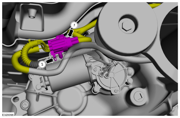
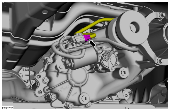
Disconnect the wiring harness connector.
-
Detach wiring harness retainers.
-
Disconnect the wiring harness connector.
 |
-
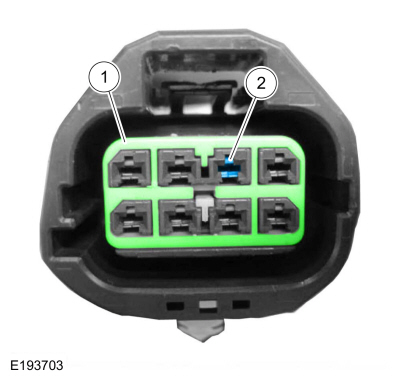
Remove the coil wire pin from the electrical connector.
-
Remove the inner retainer from the wire connector.
-
Press the release tab and remove the coil wire pin.
-
Remove the inner retainer from the wire connector.
 |
-
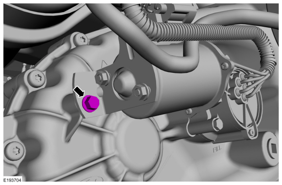
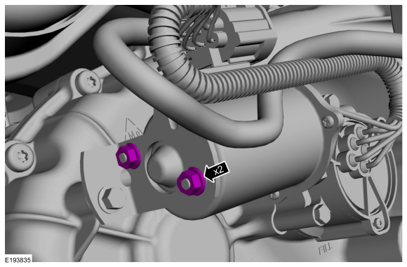
Remove the transfer case shift motor bracket bolt.
 |
-
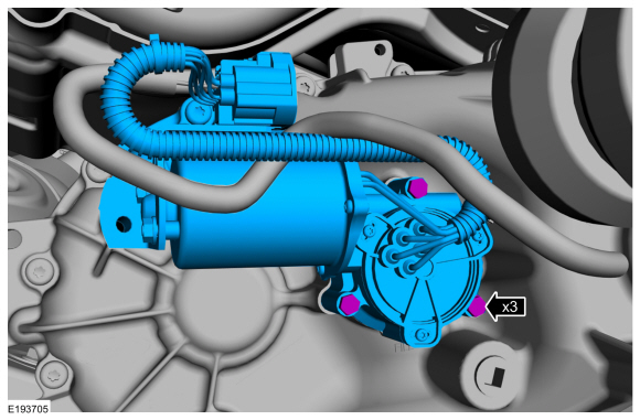
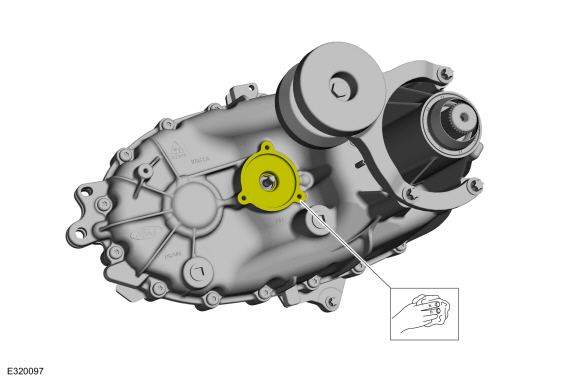
Remove the mounting bolts and the transfer case shift motor.
 |
-
Clean the transfer case shift motor mating surface.
Refer to: RTV Sealing Surface Cleaning and Preparation (303-00 Engine System - General Information, General Procedures).
 |
Installation
-
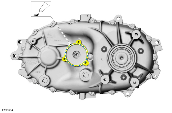
Apply a small bead of silicone sealant to the transfer case shift motor mating surface.
 |
-
NOTICE: New shift motor bracket nuts are loose and are tightened last. Failure to follow the steps in the correct order may result in damage to the component.
Install the transfer case shift motor and bolts.
Torque: 89 lb.in (10 Nm)
|
-
Install the transfer case shift motor bracket bolt.
Torque: 89 lb.in (10 Nm)
|
-
Secure the transfer case shift motor bracket nuts.
Torque: 27 lb.in (3 Nm)
 |
-
NOTE: After the wire is inserted into the connector, gently pull the wire back to verify the pin is locked inside the connector.
Install the coil wire pin in the electrical connector.
-
Insert the coil wire pin in the electrical connector.
-
Install the inner connector retainer.
-
Insert the coil wire pin in the electrical connector.
 |
-
Connect the harness connector.
 |
 Transfer Case Control Module (TCCM). Removal and Installation
Removal
Remove the CJB cover.
Remove and disconnect the lower access panel.
NOTE:
The TCCM has slotted mounting holes...

Other information:
Lincoln Navigator 2018-2026 Workshop Manual: Front Seat Cushion Blower Motor. Removal and Installation
Removal NOTE: Driver seat shown, passenger seat similar. Raise the seat to the full up position. Depower the SRS . Refer to: Supplemental Restraint System (SRS) Depowering (501-20B Supplemental Restraint System, General Procedures). Remove the front seat cushion blower motor. Disconnect the..
Lincoln Navigator 2018-2026 Workshop Manual: Charge Air Cooler (CAC) Intake Pipe. Removal and Installation
Removal NOTICE: The turbocharger compressor vanes can be damaged by even the smallest particles. When removing any turbocharger or engine air intake system component, ensure that no debris enters the system. Failure to do so may result in damage to the turbocharger. NOTE: Removal steps in this procedure may contain installation details. Charge air cooler (CAC) intake p..
Categories
- Manuals Home
- 4th Gen Lincoln Navigator Service Manual (2018 - 2026)
- Body Control Module (BCM). Removal and Installation
- Transmission Fluid Drain and Refill. General Procedures
- Liftgate Trim Panel. Removal and Installation
- Windshield Washer Pump. Removal and Installation
- Rear View Mirrors - System Operation and Component Description. Description and Operation
Front Driveshaft. Removal and Installation
Special Tool(s) / General Equipment
Crimping ToolMaterials
Name Specification Motorcraft® Premium Long-Life GreaseXG-1-E1 ESA-M1C75-B
Removal
With the vehicle in NEUTRAL, position the vehicle on a hoist.Refer to: Jacking and Lifting (100-02 Jacking and Lifting, Description and Operation).
Remove the bolts and the transmission shield.