Lincoln Navigator: Transfer Case / Transfer Case. Installation
-
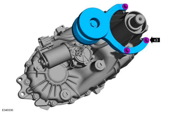
If removed, install the vibration damper to the transfer case.
Torque: 177 lb.in (20 Nm)
 |
-
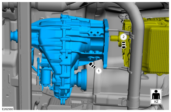
NOTE: The help of an assistant will be required.
Position the transfer case on the crossmember. Lower the transmission approximately 25.4 mm (1 in).
 |
-
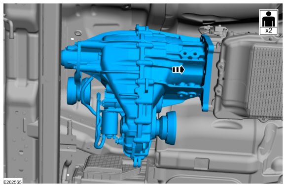
NOTE: The help of an assistant will be required.
Position the transfer case to the transmission and onto the output shaft.
 |
-
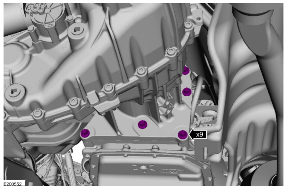
NOTE: Do not reuse the old transfer case-to-transmission bolts.
Install new transfer case-to-transmission bolts.
Torque: 168 lb.in (19 Nm)
 |
-
Install the transmission support insulator.
Refer to: Transmission Support Insulator (307-01 Automatic Transmission - 10-Speed Automatic Transmission – 10R80, Removal and Installation).
-
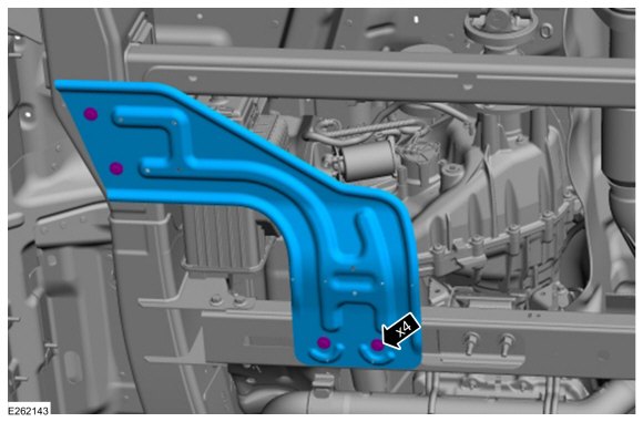
Install the LH exhaust support bracket and bolt.
Torque: 41 lb.ft (55 Nm)
 |
-
Install the transmission support crossmember.
Refer to: Transmission Support Crossmember (502-02 Full Frame and Body Mounting, Removal and Installation).
-
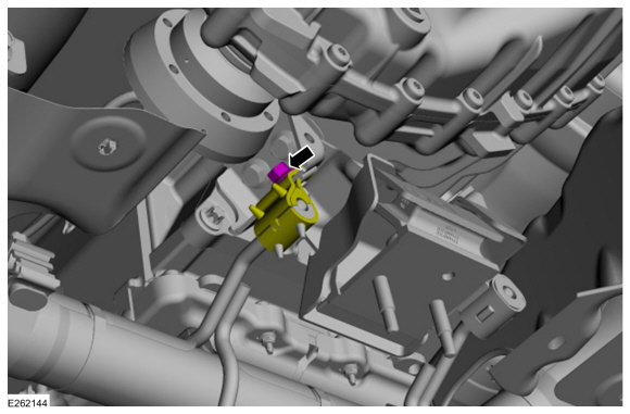
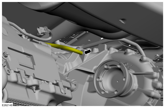
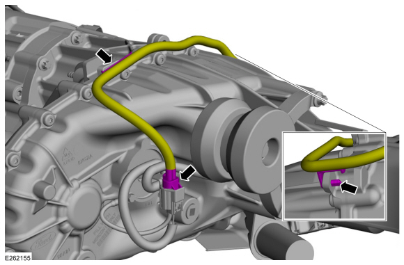
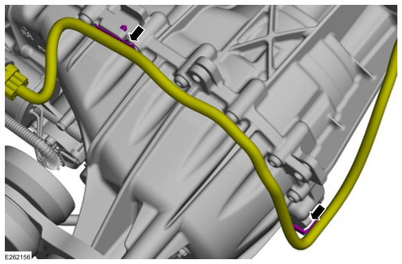
Connect the vent hose to the transfer case.
 |
Vehicles With: 1-Speed Torque On Demand Transfer Case
-
Connect the electrical connector and attach the harness retainer clip from the transfer case.
 |
Vehicles With: 2-Speed Torque On Demand Transfer Case
-
Connect the shift motor electrical connector.
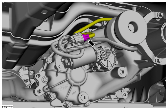 |
-
Connect the shift motor electrical connector.
 |
All vehicles
-
NOTE: Align the index marks made during removal.
Install the rear driveshaft.
Refer to: Rear Driveshaft (205-01 Driveshaft, Removal and Installation).
-
NOTE: Align the index marks made during removal.
Install the front driveshaft.
Refer to: Front Driveshaft (205-01 Driveshaft, Removal and Installation).
-
Check the transfer case fluid level.
Refer to: Transfer Case Draining and Filling (307-07B Transfer Case, General Procedures).
-
If equipped.
Position the skid plate and install the skid plate bolts.
Torque: 30 lb.ft (40 Nm)
 |


Other information:
Lincoln Navigator 2018-2026 Workshop Manual: Turbocharger Oil Return Tube RH. Removal and Installation
Materials Name Specification Motorcraft® Metal Brake Parts CleanerPM-4-A, PM-4-B, APM-4-C - Removal NOTICE: The turbocharger compressor vanes can be damaged by even the smallest particles. When removing any turbocharger or engine air intake system component, ensure that no debris enters the system. Failure to do so may result in damage to the tur..
Lincoln Navigator 2018-2026 Workshop Manual: Torque Converter Clutch (TCC). Diagnosis and Testing
Torque Converter Clutch (TCC) For torque converter operation, REFER to: Torque Converter (307-01 Automatic Transmission - 10-Speed Automatic Transmission – 10R80, Description and Operation). Condition Possible Sources Action TCC does not apply TCC solenoid mechanically stuck OFF INSTALL a new TCC ..
Categories
- Manuals Home
- 4th Gen Lincoln Navigator Service Manual (2018 - 2026)
- Transmission Fluid Drain and Refill. General Procedures
- Vehicle Dynamics Control Module (VDM). Removal and Installation
- Telematics Control Unit (TCU) Module. Removal and Installation
- Power Running Board (PRB). Diagnosis and Testing
- Front Seat. Removal and Installation
Front Driveshaft. Removal and Installation
Special Tool(s) / General Equipment
Crimping ToolMaterials
Name Specification Motorcraft® Premium Long-Life GreaseXG-1-E1 ESA-M1C75-B
Removal
With the vehicle in NEUTRAL, position the vehicle on a hoist.Refer to: Jacking and Lifting (100-02 Jacking and Lifting, Description and Operation).
Remove the bolts and the transmission shield.