Lincoln Navigator: Steering Column / Steering Column Tilt Motor. Removal and Installation
Removal
NOTE: Removal steps in this procedure may contain installation details.
-
Remove the steering column.
Refer to: Steering Column (211-04 Steering Column, Removal and Installation).
-
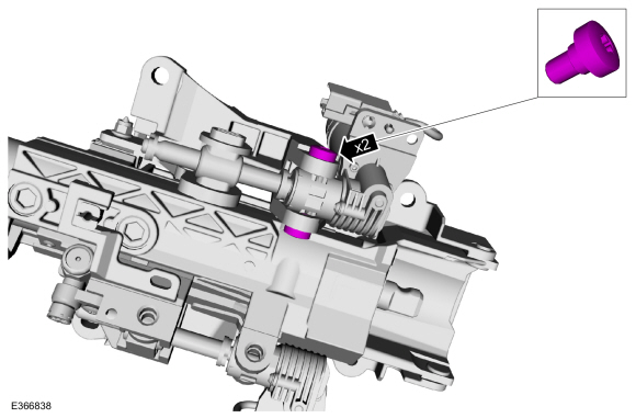
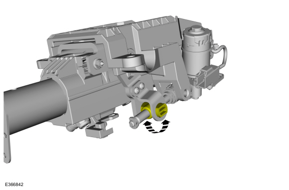
Remove the tilt motor retainers.
Torque: 62 lb.in (7 Nm)
 |
-
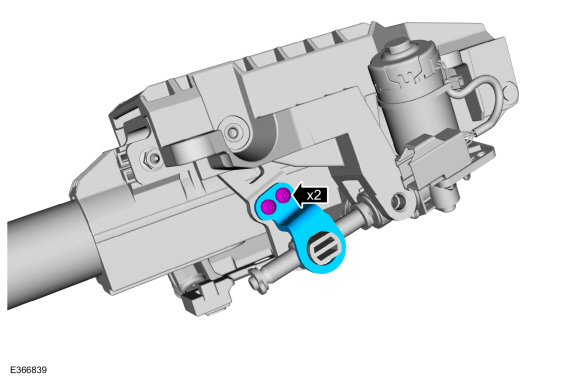
Remove the retainers and the trunnion nut capture bracket.
Torque: 62 lb.in (7 Nm)
 |
-
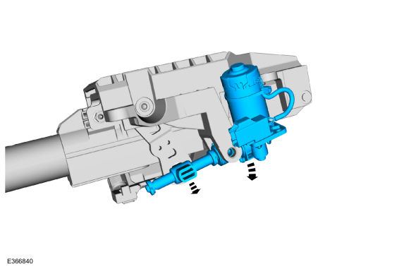
Remove the tilt motor assembly.
 |
Installation
-
To install, reverse the removal procedure.
-
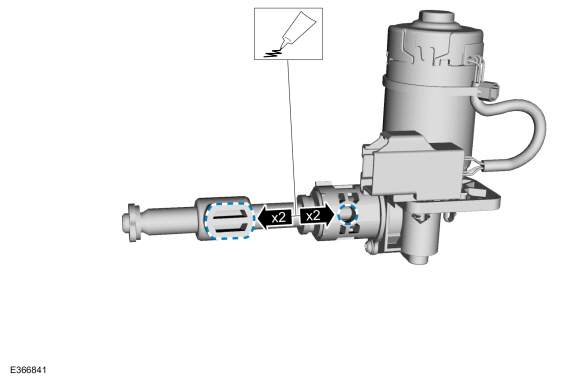
Apply grease (supplied with the new motor) to the
trunnion nut axles and the tilt motor lead-screw housing holes.
 |
-
Rotate the trunnion nut until the correct length is
achieved to align the leadscrew housing with the threaded holes in the
support arm.
 |
-
If equipped with memory steering column, use the
steering column control switch and set the soft stops as follows.
-
Move the column up until it reaches the end of
travel and hold the switch for 2 seconds after the column has reached
the end of travel.
-
Move the column in the same direction until it
reaches the end of travel again and hold the switch for 2 seconds after
the motor has reached the end of travel. This clears any unintended soft
stops.
-
Move the column down until it reaches the end of
travel and hold the switch for 2 seconds after the motor has reached the
end of travel.
-
Move the column in the same direction until it
reaches the end of travel and hold the switch for 2 seconds after the
motor has reached the end of travel. This clears any unintended soft
stops.
-
Move the column up until it reaches the end of
travel and hold the switch for 2 seconds after the column has reached
the end of travel.
 Steering Column Telescopic Motor. Removal and Installation
Removal
NOTE:
Removal steps in this procedure may contain installation details.
Remove the steering column.
Refer to: Steering Column (211-04 Steering Column, Removal and Installation)...
 Steering Column Upper Shaft. Removal and Installation
Removal
NOTE:
Removal steps in this procedure may contain installation details.
NOTE:
Do not allow the steering column to rotate while the
steering column shaft is disconnected or damage to the steering column
internal sensor may result...
Other information:
Lincoln Navigator 2018-2026 Workshop Manual: Rear Climate Control - System Operation and Component Description. Description and Operation
System Operation System Diagram *.sttxt { visibility: hidden; } *.stcallout { visibility: visible; } E370663 ..
Lincoln Navigator 2018-2026 Workshop Manual: Liftgate Window Glass. Removal and Installation
Removal NOTE: Removal steps in this procedure may contain installation details. Open the liftgate window glass. NOTE: Liftgate shown closed for clarity. Disconnect the heated rear window element electrical connectors. Remove the rear spoiler. Refer to: Rear Spoiler (501..
Categories
- Manuals Home
- 4th Gen Lincoln Navigator Service Manual (2018 - 2026)
- Rear View Mirrors - System Operation and Component Description. Description and Operation
- Vehicle Dynamics Control Module (VDM). Removal and Installation
- Front Seat. Removal and Installation
- All Terrain Control Module (ATCM). Removal and Installation
- Neutral Flat Tow Activation and Deactivation. General Procedures
Rear Drive Halfshafts. Diagnosis and Testing
Preliminary Inspection
Visually inspect the CV joints, housing, boots, and clamps for obvious signs of mechanical damage.If an obvious cause for an observed or reported concern is found, correct the cause (if possible) before proceeding to the next step
If the cause is not visually evident, verify the symptom and REFER to Symptom Chart: NVH.