Lincoln Navigator: Steering Column / Steering Column Motor Lubrication. General Procedures
Materials
| Name | Specification |
|---|---|
| Motorcraft® Premium Long-Life Grease XG-1-E1 |
ESA-M1C75-B |
Adjustment
-
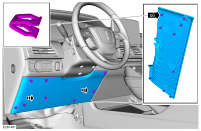
Remove the steering column opening trim panel.
 |
-
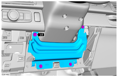
Remove the bolts and the steering column reinforcement panel. Torque:80 lb.in (9 Nm)
 |
-
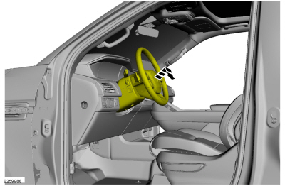
Fully extend and lower the steering column.
 |
-
Remove the steering column shrouds.
Refer to: Steering Column Shrouds (501-05 Interior Trim and Ornamentation, Removal and Installation).
-
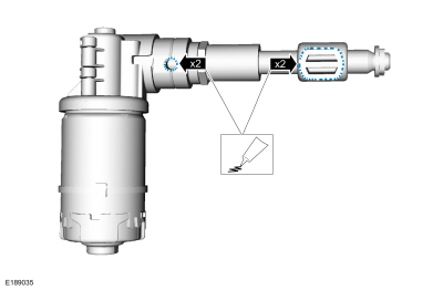
Apply grease to the trunnion nut axles and the tilt motor lead-screw housing holes.
Material: Motorcraft® Premium Long-Life Grease / XG-1-E1 (ESA-M1C75-B)
 |
-
Apply grease to the trunnion nut axles and the telescopic motor lead-screw housing holes.
Material: Motorcraft® Premium Long-Life Grease / XG-1-E1 (ESA-M1C75-B)
|
-
Retest Tilt and Telescopic motor operation.
-
If the noise is still present, Using an Engine Ear,
Mechanics Stethoscope or suitable listening device, Attempt to isolate
the source of the Steering Column noise.
-
If the noise can be isolated to an internal tilt or telescopic motor concern, Replace the suspect motor.
Refer to: Steering Column Tilt Motor (211-04 Steering Column, Removal and Installation).
Refer to: Steering Column Telescopic Motor (211-04 Steering Column, Removal and Installation).
 Steering Column. Diagnosis and Testing
Diagnostic Trouble Code (DTC) Chart
Diagnostics in this manual assume a certain skill level and knowledge of Ford-specific diagnostic practices. REFER to: Diagnostic Methods (100-00 General Information, Description and Operation)...
 Steering Column. Removal and Installation
Removal
NOTE:
Power adjustable column shown, manual column similar.
NOTE:
Removal steps in this procedure may contain installation details...
Other information:
Lincoln Navigator 2018-2026 Workshop Manual: Passive Anti-Theft System (PATS) - Overview. Description and Operation
Overview NOTE: This section only describes and diagnosis the Phone as a Key system. In order for the Phone as a Key system to operate, the PATS system must be functioning correctly. For more information about the PATS system Refer to: Passive Anti-Theft System (PATS) - Component Location (419-01C Passive Anti-Theft System (PATS) - Vehicles With: Phone as a Key, Description and O..
Lincoln Navigator 2018-2026 Workshop Manual: Vehicle Dynamic Suspension. Diagnosis and Testing
Diagnostic Trouble Code (DTC) Chart Diagnostics in this manual assume a certain skill level and knowledge of Ford-specific diagnostic practices. REFER to: Diagnostic Methods (100-00 General Information, Description and Operation). Module DTC Description Action VDM C110C:11 Left Front Damper Solenoid: Circuit Short To Ground GO to Pinpoint Test D VDM C110C..
Categories
- Manuals Home
- 4th Gen Lincoln Navigator Service Manual (2018 - 2026)
- Front Seat. Removal and Installation
- Brake Service Mode Activation and Deactivation. General Procedures
- Body and Paint
- Transmission Fluid Drain and Refill. General Procedures
- Remote Function Actuator (RFA) Module. Removal and Installation
Wheel to Hub Runout Minimization. General Procedures
Check
NOTE: Wheel-to-hub optimization is important. Clearance between the wheel and hub can be used to offset or neutralize the Road Force® or run-out of the wheel and tire assembly. For every 0.001 inch of wheel-to-hub clearance, the Road Force® can be affected between 1 and 3 pounds depending on the tire stiffness.
NOTE: The example below illustrates how the clearance between the wheel and the hub can be used to offset the high spot of radial run-out or Road Force®. Following the procedure will make sure of the best optimization.
Position the wheel and tire assembly on the vehicle so that the high spot location of radial run-out or Road Force® is at the 6 o'clock position and