Lincoln Navigator: Suspension System - General Information / Ride Height Measurement. General Procedures
Special Tool(s) / General Equipment
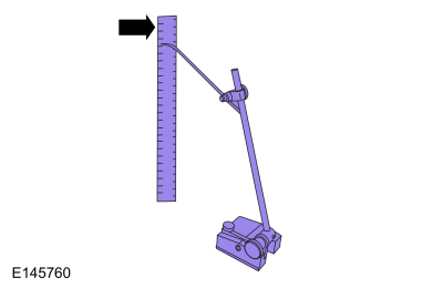
| Surface Gauge |
Check
Ride Height Measurement — Front
-
NOTE: Make sure that the vehicle is positioned on a flat, level surface and the tires are inflated to the correct pressure. Vehicle should have a full tank of fuel.
Jounce front and rear suspension vigorously to allow the vehicle to settle.
-
Before measuring ride height check:
-
Tires are inflated to the correct pressure.
-
Vehicle should have at least one-half tank of fuel.
-
All fluids at proper levels.
-
No cargo inside the cab or bed.
-
Inspect for aftermarket equipment. Check for
aftermarket changes to the steering, suspension, wheel and tire
components (such as competition, heavy duty, etc.).
-
Tires are inflated to the correct pressure.
-
-
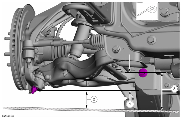
Ride height = 3 - 2
-
Measure the distance between the flat level
surface and the lowest point on the wheel knuckle. (measurement 2)
Use the General Equipment: Surface Gauge
-
Measure the distance between the flat level
surface and the center of the rearward lower arm bolt. (measurement 3)
Use the General Equipment: Surface Gauge
-
Ride height = 3 - 2
 |
-
With the surface gauge positioned on a flat, level
surface, record the measurement of the surface gauge position
(measurement 2) and (measurement 3).
Use the General Equipment: Surface Gauge
 |
-
Subtract measurement 2 from measurement 3 to obtain the front ride height.
Ride Height Measurement — Rear
-
NOTE: Make sure that the vehicle is positioned on a flat, level surface, transmission in the PARK position and the parking brake OFF.
Jounce front and rear suspension vigorously to allow the vehicle to settle.
-
Before measuring ride height check:
-
Tires are inflated to the correct pressure.
-
Vehicle should have at least one-half tank of fuel.
-
All fluids at proper levels.
-
No cargo inside the cab or bed.
-
Inspect for aftermarket equipment. Check for
aftermarket changes to the steering, suspension, wheel and tire
components (such as competition, heavy duty, etc.).
-
Tires are inflated to the correct pressure.
-
NOTE: Make sure that the vehicle is positioned on a flat, level surface, transmission in the PARK position and the parking brake OFF.
-
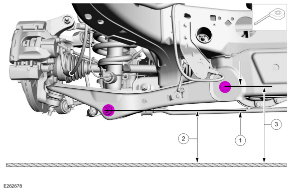
Ride height = 3 - 2
-
Measurement 3
-
Measurement 2
Use the General Equipment: Surface Gauge
-
Ride height = 3 - 2
 |
-
Measure the distance between the flat level surface
and the center of the lower arm rearward bolt (measurement 3).
-
Measure the distance between the flat level surface
and the center of the shock absorber lower bolt (rearward side)
(measurement 2).
-
Subtract measurement 2 from measurement 3 to obtain the rear ride height.
 Rear Toe Adjustment. General Procedures
Special Tool(s) /
General Equipment
Wheel Alignment System
Activation
NOTICE:
Do not use any tools or equipment to move the wheel and tire
assembly or suspension components while checking for relative movement...

Other information:
Lincoln Navigator 2018-2026 Workshop Manual: Steering Column Upper Shaft. Removal and Installation
Removal NOTE: Removal steps in this procedure may contain installation details. NOTE: Do not allow the steering column to rotate while the steering column shaft is disconnected or damage to the steering column internal sensor may result. NOTE: Use a steering wheel holding device (such as Hunter® 28-75-1 or equivalent). Keep the steering wheel in the s..
Lincoln Navigator 2018-2026 Workshop Manual: Cylinder Head RH. Removal and Installation
Special Tool(s) / General Equipment Long Nose Pliers Materials Name Specification Motorcraft® Silicone Gasket RemoverZC-30-A, AZC-30-C - Motorcraft® Metal Surface Prep WipesZC-31-B - Removal NOTICE: During engine repair procedures, cleanliness is extremely important. Any foreign material, including any material c..
Categories
- Manuals Home
- 4th Gen Lincoln Navigator Service Manual (2018 - 2026)
- Windshield Washer Pump. Removal and Installation
- Body and Paint
- Head Up Display (HUD) Module Calibration. General Procedures
- Front Seat. Removal and Installation
- Rear Bumper. Removal and Installation
Front Driveshaft. Removal and Installation
Special Tool(s) / General Equipment
Crimping ToolMaterials
Name Specification Motorcraft® Premium Long-Life GreaseXG-1-E1 ESA-M1C75-B
Removal
With the vehicle in NEUTRAL, position the vehicle on a hoist.Refer to: Jacking and Lifting (100-02 Jacking and Lifting, Description and Operation).
Remove the bolts and the transmission shield.