Lincoln Navigator: Instrument Panel and Console / Overhead Console. Removal and Installation
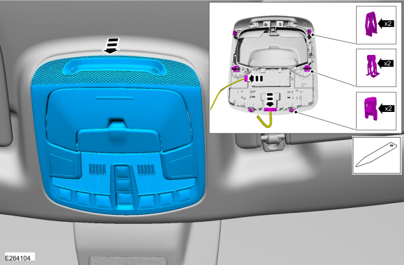
Removal
-
Release the clips and remove the overhead console.
-
Disconnect the electrical connectors.
-
Disconnect the electrical connectors.
 |
Installation
-
To install, reverse the removal procedure.
-
NOTE: This step is only necessary when installing a new overhead console assembly.
Using a diagnostic scan tool, carry out the LIN New Module Initialization procedure (Toolbox>BCM (body control module)LIN New Module Initialization).
-
NOTE: This step is only necessary when installing a new overhead console assembly.
Carry out the BCM self-test. Clear the DTC and then retrieve the DTC from the BCM to confirm all DTC have been cleared.
 Instrument Panel Upper Section. Removal and Installation
Special Tool(s) /
General Equipment
Interior Trim Remover
Removal
NOTE:
Removal steps in this procedure may contain installation details...

Other information:
Lincoln Navigator 2018-2026 Workshop Manual: Differential Carrier. Disassembly and Assembly
Special Tool(s) / General Equipment 205-386 (T97T-4205-D) Gauge, Differential (Traction Lock)TKIT-1998-LM (NavigatoR)TKIT-1997-F/FLM/LT Hydraulic Press Punch Copper Hammer Bearing Separator Materials Name Specification Motorcraft® SAE 75W-85 Premium Synthetic Hypoid Gear LubricantXY-75W85-QL WSS-M2C942-A D..
Lincoln Navigator 2018-2026 Workshop Manual: Connecting Rod Bearing Journal Clearance. General Procedures
Check NOTE: Refer to the appropriate Section 303-01 for the specification. NOTE: The crankshaft connecting rod journals must be within specifications to check the connecting rod bearing journal clearance. Remove the connecting rod bearing cap and connecting rod bearing. Position a piece of Plastigage across the bearing surface. ..
Categories
- Manuals Home
- 4th Gen Lincoln Navigator Service Manual (2018 - 2026)
- All Terrain Control Module (ATCM). Removal and Installation
- SYNC Module [APIM]. Removal and Installation
- Body and Paint
- Transmission Fluid Level Check. General Procedures
- Front Seat. Removal and Installation
Wheel to Hub Runout Minimization. General Procedures
Check
NOTE: Wheel-to-hub optimization is important. Clearance between the wheel and hub can be used to offset or neutralize the Road Force® or run-out of the wheel and tire assembly. For every 0.001 inch of wheel-to-hub clearance, the Road Force® can be affected between 1 and 3 pounds depending on the tire stiffness.
NOTE: The example below illustrates how the clearance between the wheel and the hub can be used to offset the high spot of radial run-out or Road Force®. Following the procedure will make sure of the best optimization.
Position the wheel and tire assembly on the vehicle so that the high spot location of radial run-out or Road Force® is at the 6 o'clock position and