
Lincoln Navigator: Exterior Lighting / Lighting Driver Control Module. Removal and Installation
Removal
NOTE: Removal steps in this procedure may contain installation details.
NOTE: LH (left-hand) headlamp assembly shown, RH (right-hand) headlamp assembly similar.
- Using a diagnostic scan tool, begin the PMI process for the LDCM following the on-screen instructions.
-
Remove the headlamp assembly.
Refer to: Headlamp Assembly (417-01 Exterior Lighting, Removal and Installation).
-
Remove the screws and position out the LED control module.
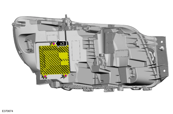 |
-
Disconnect the electrical connectors and remove the LED control module.
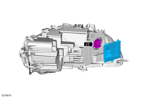 |
Installation
-
To install, reverse the removal procedure.
-
NOTE: Carry out this step only when a LED (light emitting diode) headlamp module is being replaced.
Using a diagnostic scan tool, finish the PMI process for the LDCM following the on-screen instructions.
 Light Sensor. Removal and Installation
Special Tool(s) /
General Equipment
Interior Trim Remover
Removal
Using a non-marring tool release and position the light sensor...
 Rear Fog Lamp. Removal and Installation
Removal
NOTE:
RH (right-hand) rear fog lamp shown, LH (left-hand) similar.
Remove the nuts and the rear fog lamp.
Disconnect the electrical connector...
Other information:
Lincoln Navigator 2018-2026 Workshop Manual: Instrument Panel Cluster (IPC) - System Operation and Component Description. Description and Operation
System Operation System Diagram - Gauges *.sttxt { visibility: hidden; } *.stcallout { visibility: visible; } 1 PCM 2 GWM 3 Fuel Pump and Sender Unit 4 IPC 5 Speedometer 6 Tachometer 7 Temperature ..
Lincoln Navigator 2018-2026 Workshop Manual: Accelerator Pedal. Removal and Installation
Removal NOTE: Removal steps in this procedure may contain installation details. NOTE: To prevent setting Diagnostic Trouble Codes (DTCs), make sure the ignition switch is in the OFF position prior to disconnecting the accelerator pedal electrical connector. NOTE: Vehicles with adjustable pedals, position the driver's seat to the full rearward position and, if possible, a..
Categories
- Manuals Home
- 4th Gen Lincoln Navigator Service Manual (2018 - 2026)
- Identification Codes. Description and Operation
- Telematics Control Unit (TCU) Module. Removal and Installation
- Vehicle Dynamics Control Module (VDM). Removal and Installation
- Brake Service Mode Activation and Deactivation. General Procedures
- Power Running Board (PRB). Diagnosis and Testing
Wheel to Hub Runout Minimization. General Procedures
Check
NOTE: Wheel-to-hub optimization is important. Clearance between the wheel and hub can be used to offset or neutralize the Road Force® or run-out of the wheel and tire assembly. For every 0.001 inch of wheel-to-hub clearance, the Road Force® can be affected between 1 and 3 pounds depending on the tire stiffness.
NOTE: The example below illustrates how the clearance between the wheel and the hub can be used to offset the high spot of radial run-out or Road Force®. Following the procedure will make sure of the best optimization.
Position the wheel and tire assembly on the vehicle so that the high spot location of radial run-out or Road Force® is at the 6 o'clock position and