Lincoln Navigator: Engine - 3.5L EcoBoost (272kW/370PS) / Intake Manifold. Removal and Installation
Removal
-
Disconnect the battery ground cable.
Refer to: Battery Disconnect and Connect (414-01 Battery, Mounting and Cables, General Procedures).
-
Remove the EGR cooler.
Refer to: Exhaust Gas Recirculation (EGR) Cooler (303-08 Engine
Emission Control - 3.5L EcoBoost (272kW/370PS), Removal and
Installation).
-
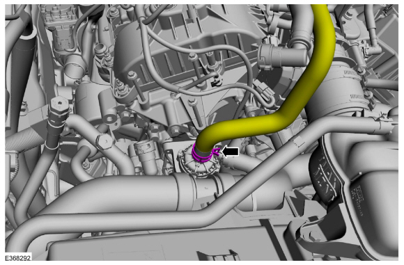
Disconnect the cabin heater coolant pump heater hose.
-
Disconnect the heater hose from the intake manifold and position aside.
-
-
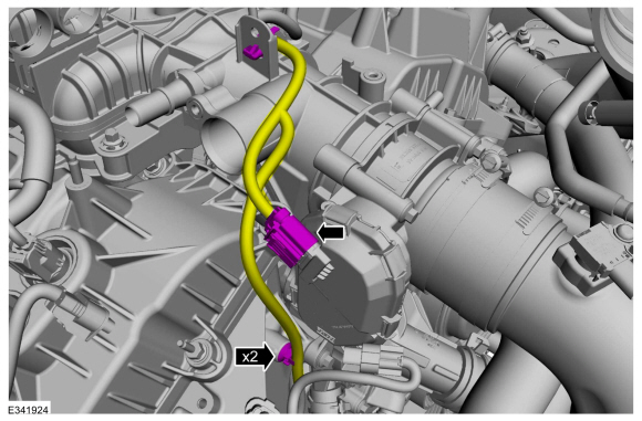
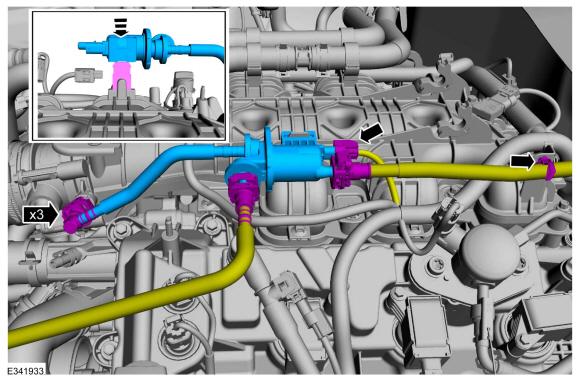
Detach the pin-type retainer.
-
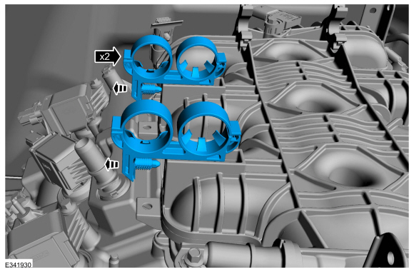
Disconnect the electrical connector.
-
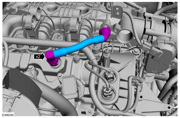
Follow directions to release the quick release coupling type 5.
Refer to: Quick Release Coupling (310-00 Fuel System - General Information - 3.5L EcoBoost (272kW/370PS), General Procedures).
-
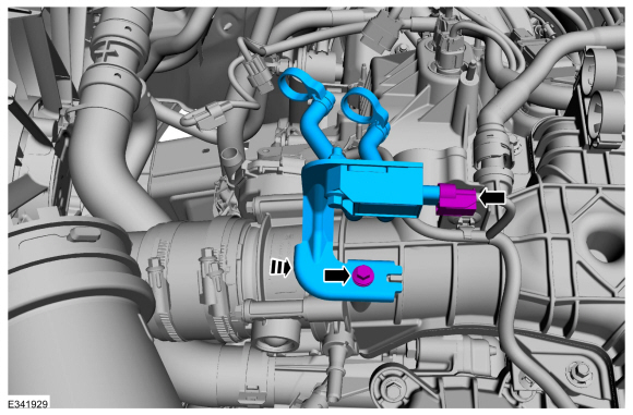
Remove the fuel vapor purge valve.
-
This step is only necessary if installing new intake manifold.
Disconnect the electrical connector, remove the retainer and the differential pressure feedback EGR sensor.
-
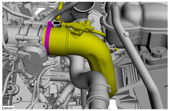
Disconnect the throttle body electrical connector and wiring harness retainers.
-
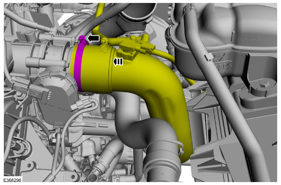
Loosen the clamp and position the throttle body intake pipe aside.
-
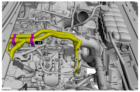
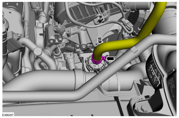
Follow directions to release the quick release coupling type 3. Remove the PCV tube.
Refer to: Quick Release Coupling (310-00 Fuel System - General Information - 3.5L EcoBoost (272kW/370PS), General Procedures).
-
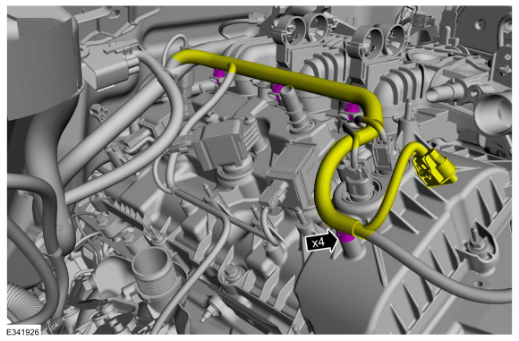
Disconnect the wire harness retainers.
-
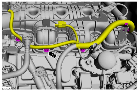
Disconnect the wire harness retainers from the intake manifold.
-
Disconnect the electrical connects and remove the wire harness retainers from the intake manifold.
-
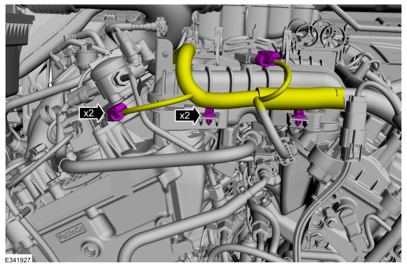
This step is only necessary if installing new intake manifold.
Detach the heater hose clamps from the intake manifold.
-
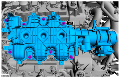
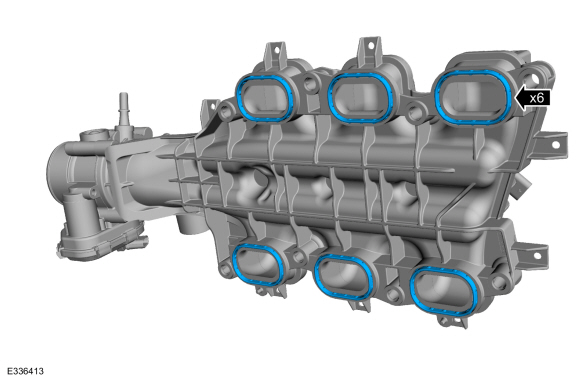
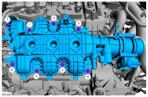
Remove the bolts and the intake manifold.
-
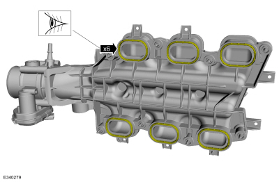
Inspect the gaskets for nicks, cuts and abrasions. If
these conditions are not present, the gasket may be re-used.
-
NOTE:
This step only necessary if there are any nicks, cuts or abrasions present.
-
Clean and inspect all of the sealing surfaces of the cylinder heads and the intake manifold.
Installation
-
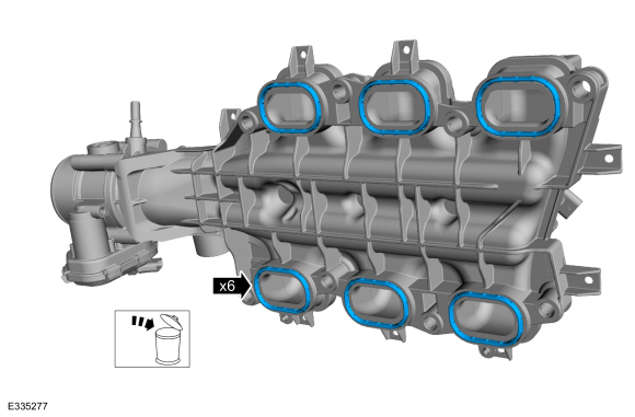
If gaskets were discarded install new intake manifold gaskets.
-
NOTICE:
If the engine is repaired or replaced because of
upper engine failure, typically including valve or piston damage, check
the intake manifold for metal debris. If metal debris is found, install a
new intake manifold. Failure to follow these instructions can result in
engine damage.
Install the intake manifold and the bolts.
Torque:
Stage 1:
89 lb.in (10 Nm)
Stage 2:
45°
-
This step is only necessary if installing new intake manifold.
Attach the heater hose clamps to the intake manifold.
-
Install the wire harness retainers to the intake manifold and connect the electrical connectors.
-
Attach the wire harness retainers to the intake manifold.
-
Attach the wire harness retainers.
-
Follow directions to install quick release coupling type 3. Install the PCV tube.
Refer to: Quick Release Coupling (310-00 Fuel System - General Information - 3.5L EcoBoost (272kW/370PS), General Procedures).
-
Attach the wiring harness retainers and connect the throttle body electrical connector.
-
Position back the throttle body intake pipe and tighten the clamp.
Torque:
44 lb.in (5 Nm)
-
This step is only necessary if installing new intake manifold.
Install the differential pressure feedback EGR sensor and bolt. Connect the electrical connector.
Torque:
89 lb.in (10 Nm)
-
-
Install the fuel vapor purge valve.
-
Follow directions to connect the quick release couplings type 5.
Refer to: Quick Release Coupling (310-00 Fuel System - General Information - 3.5L EcoBoost (272kW/370PS), General Procedures).
-
Attach the pin-type retainer.
-
Connect the electrical connector.
-
Connect the heater hose to the intake manifold.
-
Connect the cabin heater coolant pump heater hose.
-
Install the EGR cooler.
Refer to: Exhaust Gas Recirculation (EGR) Cooler (303-08 Engine
Emission Control - 3.5L EcoBoost (272kW/370PS), Removal and
Installation).
-
Connect the battery ground cable.
Refer to: Battery Disconnect and Connect (414-01 Battery, Mounting and Cables, General Procedures).
-
Road test the vehicle.
Removal
Remove the roller finger follower.
Refer to: Rocker Arm (303-01 Engine - 3.5L EcoBoost (272kW/370PS), Removal and Installation)...
Special Tool(s) /
General Equipment
Oil Drain Equipment
Hose Clamp Remover/Installer
Locking Pliers
Removal
With the vehicle in NEUTRAL, position it on a hoist...
Other information:
Removal
NOTE:
Removal steps in this procedure may contain installation details.
NOTE:
LH side shown, RH side similar.
Remove the front wheel and tire assembly.
Refer to: Wheel and Tire (204-04A Wheels and Tires, Removal and Installation)...
Special Tool(s) /
General Equipment
Feeler Gauge
Check
NOTE:
Refer to the appropriate Section 303-01 for the specification.
NOTE:
Use a Straightedge that is calibrated by the
manufacturer to be flat within 0...


 Hydraulic Lash Adjuster. Removal and Installation
 Oil Cooler. Removal and Installation